[转]Transformation in OCCT
Transformation matrix is a fundamental entity in areas like graphics, robotics, animations, modeling and many others. This article provides an introduction to transformations in Open CASCADE Technology.
OCCT provides several classes for working with transformations in 3D space:
- gp_Vec
3-component vector defining translation. - gp_Quaternion
4-component vector defining rotation quaternion. - gp_Mat
3×3 matrix which may define rotation, scaling, mirroring. - gp_Trsf
4×3 matrix defining a common transformation (excluding affinity and similar). - gp_GTrsf
4×3 matrix defining a general transformation (including affinity). - NCollection_Mat4
4×4 matrix defining an arbitrary transformation. - TopLoc_Datum3D, Geom_Transformation
Handle classes over gp_Trsf (for using via smart-pointers). - TopLoc_Location
Sequence of transformations defined by TopLoc_Datum3D/gp_Trsf. - BRepBuilderAPI_Transform
Algorithm applying common gp_Trsf transformation onto shape (TopoDS_Shape). - BRepBuilderAPI_GTransform
Algorithm applying general gp_GTrsf transformation onto shape (TopoDS_Shape).
2D space transformation classes look very close to their 3D analogs:
- gp_Vec2d
2-component vector defining translation - gp_Mat2d
2×2 matrix - gp_Trsf2d
3×2 matrix defining a common transformation - gp_GTrsf2d
3×2 matrix defining a general transformation - Geom2d_Transformation
Handle class over gp_Trsf2d (for using via smart-pointers)
Transformation in Geometry
From linear algebra you may know how useful a 4×4 matrix could be. This matrix may define almost any form of transformation, including translation, scaling, rotation, shear, mirror, and projection. Applying transformation to 3D point is as simple as multiplying 4×4 matrix to 4D vector with 4th component set to 1.0.
   V1  V2  V3   T    XYZ     XYZ
| a11 a12 a13 a14 | | x |   | x'|
| a21 a22 a23 a24 | | y |   | y'|
| a31 a32 a33 a34 | | z | = | z'|
|   0   0   0   1 | | 1 |   | 1 |
4×4 matrix with a dummy 4th row (4×3 matrix), from gp_Trsf documentation.
Moreover, thanks to associative property, a sequence of 4×4 matrices can be pre-multiplied into a single one defining a total transformation – pretty handful way to spare memory and to dramatically reduce the amount of calculation on applying the same transformation to a large number of points. These reasons made 4×4 matrices commonly adopted in 3D graphics APIs and applications, so that languages like GLSL (OpenGL Shading Language) even define such matrices as primitive types:
mat4 uProjMat, uModelMat; // projection and model-view matrices
vec4 thePnt;              // input 3D point to transform
//vec4 aPos =  uProjMat  *  uModelMat * thePnt;  // intended transformation
//vec4 aPos =  uProjMat  * (uModelMat * thePnt); // same result
//vec4 aPos =  (uProjMat * uModelMat) * thePnt;  // same result
mat4 uCombMat = uProjMat * uModelMat;            // combined matrix
vec4 aPos = uCombMat * thePnt;                   // also the same result
GLSL pseudo-code demonstrating matrix / vector operations.
Such flexibility of 4×4 matrix has side effects. A matrix projecting 3D point onto 2D screen might be useful for rendering, but dramatically changes shape properties. For this reason, OCCT defines two basic transformation classes: gp_GTrsf (4×3 matrix) for general transformations and gp_Trsf for most commonly applied transformations.
gp_GTrsf allows affinity modifications changing shape properties – e.g. making an ellipse from a circle and so on. These transformations are dangerous, as they imply changes in underlying geometry like redefinition of making an Geom_Ellipse from Geom_Circle – something that cannot be done easily on-the-fly. For that reason, gp_GTrsf is never used as a transient modifier and usually requires applying transformation operators like BRepBuilderAPI_GTransform.
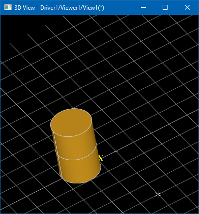
gp_Trsf further restricts the set of transformations and allows only translation, uniform scaling, rotation and mirroring. With these restrictions, gp_Trsf preserves original shape properties and proportions, so that it can be safely applied on geometry on-the-fly.Draw Harness script below demonstrates uniform (gp_Trsf, command tscale) and non-uniform (gp_GTrsf, command scalexyz) scale transformations.

uniformly scaled down (scale factor 0.5),
and non-uniformly scaled (SX=2.0, SY=1.0, SZ=1.0).
pload MODELING VISUALIZATION
# create cylinder
pcylinder cyl 1 3
vinit View1
vdisplay -dispMode 1 cyl
vfit
# apply uniform scale
tscale cyl 0 0 0 0.5
vdisplay -dispMode 1 cyl
# apply non-uniform scale
scalexyz cyl3 cyl 2.0 1.0 1.0
vdisplay -dispMode 0 cyl3
TRS (Translation + Rotation + Scaling) is a golden triplet defining most commonly used transformations. Defining the translation part of gp_Trsf looks straightforward – it is just a vector. Scaling takes two parameters – scale factor and scale origin:
gp_Trsf aTranslation;
aTranslation.SetTranslation (gp_Vec (10.0, 0.0, 0.0));

gp_Trsf aScaling;
aScaling.SetScale (gp_Pnt (10.0, 0.0, 0.0), 5.0);
Rotation part is more involving and may be defined in numerous ways:
- Axis (gp_Ax1) and angle.
- Euler angles triplet.
- 4-component quaternion (gp_Quaternion).
- 3×3 rotation matrix (gp_Mat).
gp_Trsf aRotation;
gp_Quaternion aQuat;
aQuat.SetEulerAngles (gp_YawPitchRoll, M_PI, M_PI * 0.5, 0.0);
aRotation.SetRotation (aQuat);
gp_Trsf might be also defined as a transformation from one coordinate system (gp_Ax3) to another one:
gp_Ax3 anAxes1 = gp::XOY();
gp_Ax3 anAxes2 = gp::YOZ();
gp_Trsf aTrsf;
aTrsf.SetTransformation (anAxes1, anAxes2);
It is important to remember that matrix multiplication (and, hence, gp_Trsf) is not commutative – the multiplication order matters! So that Translation -> Rotation -> Scaling is not the same as Scaling -> Rotation -> Translation.
From a logical point of view, though, any multiplication order might make sense, but usually the scale is applied first, then comes the rotation, and then the translation. Imagine that scale factor defines length unit conversion (meters to mm), so that within T->R->S translation should be defined in initial units (meters) and within S->R->T translation should be defined in destination units (mm).Note that transformation order of gp_Trsf should be read from right to left within multiplication sequence:
gp_Trsf aTranslation, aRotation, aScaling;
aTranslation.SetTranslation (gp_Vec (10.0, 0.0, 0.0));
aRotation.SetRotation (gp_Ax1 (gp::Origin(), gp::DZ()), M_PI);
aScaling.SetScale (gp_Pnt (10.0, 0.0, 0.0), 5.0);

// Scale -> Rotate -> Translate
gp_Trsf aTrsfSRT = aTranslation * aRotation * aScaling;
// Translate -> Rotate -> Scale
gp_Trsf aTrsfTRS = aScaling * aRotation * aTranslation;
// aTrsfTRS != aTrsfSRT
Most geometric entities from package gp define methods Transform()/Transformed() to apply gp_Trsf transformation. It is important to use a class for XYZ triplet applicable to a specific context to avoid logical errors. gp_Pnt/gp_XYZ/gp_Vec/gp_Dir – look all the same from the first glance, but gp_Dir::Transform() takes into account that scale and translation parts should not be considered for a unit vector, while gp_Pnt::Transform() respects transformation as whole.
Take a look at the Draw Harness script below performing the same transformations in different order (commands tscale, ttranslate, and trotate).
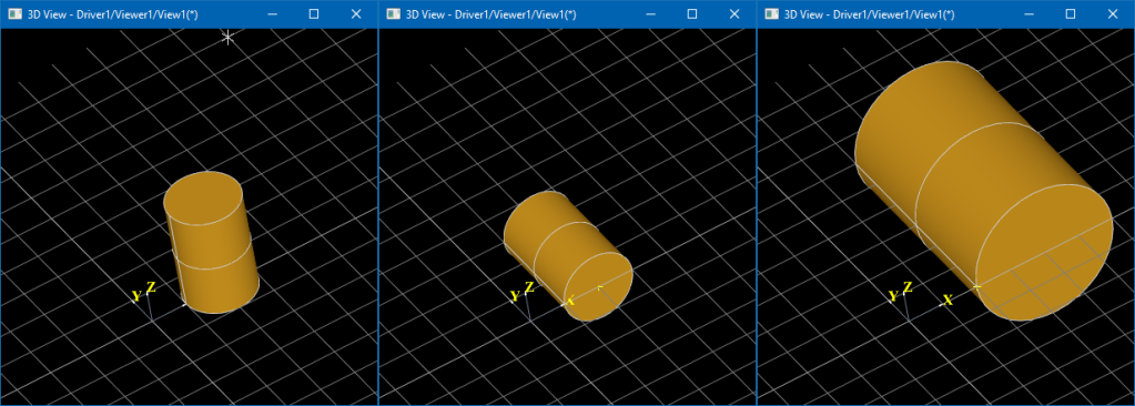

pload MODELING VISUALIZATION
vinit View1
vtrihedron t
vpoint p200 200 0 0

# 1) translate -> rotate -> scale
pcylinder cyl 100 300
vdisplay -dispMode 1 cyl
# 1.1) translate DX=200
ttranslate cyl 200 0 0
vdisplay cyl
# 1.2) rotate 90 degrees around OX axis
trotate cyl 0 0 0 1 0 0 -90
vdisplay cyl
# 1.3) 2x scale
tscale cyl 0 0 0 2.0
vdisplay cyl

# 2) scale -> rotate -> translate
pcylinder cyl 100 300
vdisplay -dispMode 1 cyl
# 2.1) 2x scale
tscale cyl 0 0 0 2.0
vdisplay cyl
# 2.2) rotate 90 degrees around OX axis
trotate cyl 0 0 0 1 0 0 -90
vdisplay cyl
# 2.3) translate DX=200
ttranslate cyl 200 0 0
vdisplay cyl
Transformation path in Topology
Each TopoDS_Shape has a location represented by a TopLoc_Location object. TopLoc_Location has a peculiar property – it defines not just a final (combined) transformation, but a sequence of transformations – TopLoc_Datum3D objects, Handles (smart-pointers) to gp_Trsf.
gp_Trsf allows defining a scale factor, but it is better avoiding scale within TopLoc_Location definition to avoid issues with OCCT algorithms. Such transformations might become explicitly forbidden in future versions of OCCT. BRepBuilderAPI_Transform should be used to apply a scale factor on a lower geometry level, instead of topology level.
Compound -> Shell #1 (Location #1) -> Face #1 (same TShape)
         └> Shell #2 (Location #2) -> Face #2 (same TShape)
Two TopoDS_Shape objects may share the same geometry (TopoDS_TShape), and TopLoc_Location definition allows identifying such shapes stored in different places of assembly structure as non-identical sub-shapes.
Moreover, two TopLoc_Location defining exactly the same gp_Trsf transformation (or even identity transformation) are not necessarily equal – when TopLoc_Datum3D are defined by different objects (smart-pointers). In this case TopoDS_Shape::IsSame() will return FALSE for two shapes sharing the same TShape but having logically (but not geometrically) different locations! Take a look at the following code:
TopLoc_Location aLoc1 = TopLoc_Location();
TopLoc_Location aLoc2 = TopLoc_Location(gp_Trsf());
TopLoc_Location aLoc3 = TopLoc_Location(gp_Trsf());
std::cout << "aLoc1 vs. aLoc2: " << aLoc1.IsEqual (aLoc2) << "\n"; // aLoc1 != aLoc2
std::cout << "aLoc2 vs. aLoc3: " << aLoc2.IsEqual (aLoc3) << "\n"; // aLoc2 != aLoc3

Graphic3d_Mat4d aMat1, aMat2, aMat3;
aLoc1.Transformation().GetMat4 (aMat1);
aLoc2.Transformation().GetMat4 (aMat2);
aLoc3.Transformation().GetMat4 (aMat3);
std::cout << "aTrsf1 vs. aTrsf2: " << aMat1.IsEqual (aMat2) << "\n"; // TRUE
std::cout << "aTrsf2 vs. aTrsf3: " << aMat2.IsEqual (aMat3) << "\n"; // TRUE
All three TopLoc_Locations (aLoc1, aLoc2 and aLoc3) define geometrically equal (identity) transformations, but TopLoc_Location::IsEqual() would return FALSE. Extending the code further with multiplications shows that:
TopLoc_Location aLoc23  = aLoc2 * aLoc3;
TopLoc_Location aLoc32  = aLoc3 * aLoc2;
TopLoc_Location aLoc321 = aLoc3 * aLoc2 * aLoc1;
std::cout << "aLoc23  vs. aLoc32: " << aLoc23 .IsEqual (aLoc32) << "\n"; // FALSE
std::cout << "aLoc321 vs. aLoc32: " << aLoc321.IsEqual (aLoc32) << "\n"; // TRUE
Two locations are equal if they are composed from the same sequence of same locations, TopLoc_Location with an empty constructor is not considered (but the result is not the same as constructing TopLoc_Location from identity gp_Trsf!).
Shape iterators TopExp_Explorer and TopoDS_Iterator by default (see optional arguments) accumulate locations in a path to the sub-shape, so that returned TopoDS_Vertex within explored TopoDS_Compound will have location combined from its own transformation, it’s parent TopoDS_Edge, it’s parent TopoDS_Wire, its’ parent TopoDS_Face, and TopoDS_Compound itself.
This OCCT concept is important to remember, when working with TopoDS_Shape hierarchies, to avoid misunderstanding and logical errors in algorithms.
Conventional box definition would require 8 shared vertices (TopoDS_TVertex), 12 edges (TopoDS_TEdge), and 6 faces (TopoDS_TFace). Consider solving a puzzle – how with help of TopLoc_Location to make a box with a minimal amount of primitives? Is it possible to define a TopoDS_Edge from a single TopoDS_TVertex having two different locations? What about defining all edges in the box from a single TopoDS_TEdge. All faces from a single TopoDS_TFace?
Transformation of Interactive Object
Interactive Objects in OCCT 3D Viewer may have individual Local Transformations defined by AIS_InteractiveObject::LocalTransformation() property in the form of TopLoc_Datum3D / gp_Trsf object.It is important to note that AIS_Shape local transformation is applied independently from location stored within displayed TopoDS_Shape. If you would like moving location of shape to Interactive Object this would look like this:
Handle(AIS_InteractiveContext) theCtx;
TopoDS_Shape theShape;

const gp_Trsf aShapeLoc = theShape.Location();
TopoDS_Shape aShape = theShape.Located (TopLoc_Location());
Handle(AIS_Shape) aShapePrs = new AIS_Shape (aShape);
aShapePrs->SetLocalTransformation (aShapeLoc);
theCtx->Display (aShapePrs, AIS_Shaded, 0, false);
//theCtx->SetLocation (aShapePrs, aShapeLoc); // for already displayed object
Assigning transformation to Interactive Object has one important advantage over displaying TopoDS_Shape non-identity location – presentation transformation can be applied dynamically, while modifying TopoDS_Shape location would require recomputing the entire presentation.
This is because location stored within TopoDS_Shape itself becomes pre-multiplied within presentation data (triangulation and polyline nodes), while the Interactive Object’s transformation is defined externally. This is a big deal when modifying location interactively or in animation (like robotics simulation). AIS_AnimationObject defining object’s animation and AIS_Manipulator dynamically modifying object’s position are two examples where this difference could be easily noticed.
It is important to use the method AIS_InteractiveContext::SetLocation() instead of AIS_InteractiveObject::SetLocalTransformation() to modify the location of the already displayed object. Interactive Context will call AIS_InteractiveObject::SetLocalTransformation() internally, but will also handle dynamic highlighting and selection entities.
The following Draw Harness script demonstrates a simple animation based on object transformation:
pload MODELING VISUALIZATION
box b 1 2 3
vinit View1
vdisplay -dispMode 1 b
vfit
vzoom 0.5
vanimation a -object b -rot1 0 0 0 1 -rot2 1 0 0 1 -start 0 -duration 1
vanim a -play
OCCT viewer supports parent/children relationships (AIS_InteractiveObject::Parent() / AIS_InteractiveObject::Children() and Graphic3d_Structure::Connect()). This is one of the reasons why transformation is called “local” in AIS_InteractiveObject::LocalTransformation() property – because final transformation AIS_InteractiveObject::Transformation() is defined implicitly as a sequence of transformations of this and parent object(s).
These low-level relationship mechanisms theoretically allow propagating an assembly structure onto a scene graph, but may easily lead to bugs and undefined behavior. The most straightforward way propagating an assembly structure is creating a plain list of objects from tree leaves with combined transformations.
Transformation persistence
Apart from traditional transformations, OCCT 3D Viewer provides an API called Transformation Persistence and defined by class Graphic3d_TransformPers. This mechanism allows an object to ignore camera orientation, or it’s particular aspect – rotation (Graphic3d_TMF_RotatePers), zoom (Graphic3d_TMF_ZoomPers), panning (Graphic3d_TMF_TriedronPers) or all of them at once (Graphic3d_TMF_2d).
To use Transformation Persistence efficiently, it is important to understand which local coordinate system each persistence defines, and how it correlates to Local Transformation:
- Graphic3d_TMF_None
Local Transformation defines the entire transformation. - Graphic3d_TMF_ZoomPers/Graphic3d_TMF_RotatePers/Graphic3d_TMF_ZoomRotatePers
Graphic3d_TransformPers::AnchorPoint() defines an origin in world coordinates of the Local Coordinate System of the object. Local Transformation defines additional transformation within this Local Coordinate System.
With the Graphic3d_TMF_ZoomPers flag applied, the translation part of this transformation is practically interpreted in pixels. - Graphic3d_TMF_2d
Graphic3d_TransformPers::Corner2d() defines the view corner – an origin of the Local Coordinate System of the object; Graphic3d_TransformPers::Offset2d() defines an additional offset (in pixels) from this view corner.
Local Transformation defines additional transformation within this Local Coordinate System with translation part interpreted in pixels; practically speaking there is rare need using Local Transformation in case of 2D persistence. - Graphic3d_TMF_TriedronPers
This flag is very close to Graphic3d_TMF_2d, but allows rotating an object with the camera.
Handle(AIS_Shape) aShapePrs = new AIS_Shape (theShape);
gp_Pnt anAnchorPoint (300.0, 200.0, 100.0);
Handle(Graphic3d_TransformPers) aZoomPers =
  new Graphic3d_TransformPers (Graphic3d_TMF_ZoomPers, anAnchorPoint);
aShapePrs->SetTransformPersistence (aZoomPers);
Graphic3d_TransformPers::AnchorPoint() is a common source of misunderstanding – this is the only way to specify the object’s 3D position in world coordinates, as Local Transformation is applied locally. If you would like the object to rotate around its center, its local coordinate system should be defined there – which might be corrected by applying Local Transformation.
Objects with Graphic3d_TMF_ZoomRotatePers flag behave like sprites (although point sprites are implemented in a different way), while Graphic3d_TMF_RotatePers can be also called billboards or Z-sprites in other graphic applications.
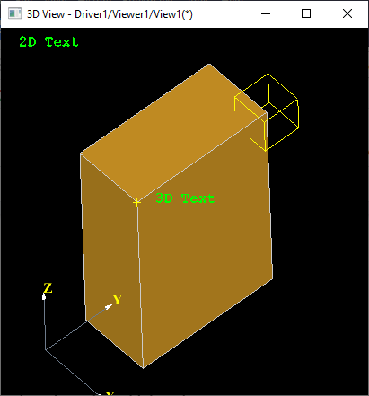
The following Draw Harness script demonstrates transformation persistence use cases:
pload MODELING VISUALIZATION

# display a normal 3D object
vinit View1
box b 100 200 300
vdisplay -dispMode 1 b
vfit

# display on-screen 2D text label
text2brep text2d "2D Text"
vdisplay  text2d -2d topLeft 20 20 -topmost

# display text at specified 3D point
vpoint pnt1 100 0 300
text2brep text3d "3D Text"
vdisplay  text3d -trsfPers zoomRotate -trsfPersPos 100 0 300
# shift label 20 pixels right from 3D point
vlocation text3d -location 20 0 0

# display trihedron at View corner with 50 pixels offset
vtrihedron trih
vdisplay   trih -trihedron bottomLeft 50 50 -topmost

# display non-zoomable 3D object
box bb 50 50 50
vdisplay  bb -trsfPers zoom -trsfPersPos 100 200 300
# move box local coordinate system to its center
vlocation bb -location -25 -25 -25
为了方便大家在移动端也能看到我的博文和讨论交流,现已注册微信公众号,欢迎大家扫描下方二维码关注。


 浙公网安备 33010602011771号