(原創) 如何在DE2-70執行Count Binary project template? (SOC) (Nios II) (DE2-70)
 Nios II EDS提供了『Count Binary』這個project template,不過在DE2與DE2-70都無法執行,本文提出解決方法。
Abstract
Nios II EDS提供了『Count Binary』這個project template,不過在DE2與DE2-70都無法執行,本文提出解決方法。
Introduction
使用環境:Quartus II 8.0 + Nios II EDS 8.0 + DE2-70 (Cyclone II EP2C70F896C6N)
回想在剛開始學習Nios II時,都會想將Nios II EDS所有的project template跑看看,不過很可惜,Count Binary就是無法在DE2與DE2-70跑,當初以為是DE2有問題,換過好幾個版子,也曾懷疑是否Nios II EDS有bug,換過好幾個Nios II版本。
因為最近在研究Using SignalTap II Embedded Logic Analyzers in SOPC Builder Systems這篇paper,指名要用Count Binary這個範例,我就順手改看看,看能不能一解之前無法順利執行的遺憾。
為什麼無法在DE2/DE2-70執行?
既然都是用Altera的FPGA,為什麼無法執行呢?假如DE2/DE2-70無法執行,那意味著其他廠商的Altera FPGA實驗版應該也無法執行,為什麼會這樣呢?
主要原因有2:
1.各ip在SOPC Builder內的命名與Count Binary不一樣,導致無法順利驅動。
2.DE2/DE2-70另外提供了七段顯示器的ip與HAL,也與Count Binary不一樣。
因為這兩個原因,導致Count Binary無法執行。
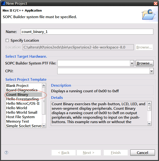
Count Binary簡介
這是一個很有趣的範例,同時用到了LEDG、七段顯示器、LCD、Console與KEY,當Nios II執行後,會從0x00一直數到0xff,之後會等待7秒鐘,繼續由0x00數到0xff,若中途按下KEY[0],會只用LCDG顯示,若中途按下KEY[1],會只用七段顯示顯示,若中途按下KEY[2],會只用LCD顯示,若按下KEY[3],會同時用LEDG、七段顯示器、LCD與Console一起顯示。
在這個範例中,可以學到
1.如何在Nios II控制LEDG、七段顯示器、LCD與console。
2.如何在Nios II使用interrupt方式控制KEY。
3.將exception stack放在on-chip memory提高整體效率。
系統架構圖

這個架構比較有疑問的應該是為什麼要使用on-chip Memory?在Using SignalTap II Embedded Logic Analyzers in SOPC Builder Systems的p.7有以下敘述:
因為這篇paper本來就是要拿SignalTap II來觀察Nios II與SOPC系統,所以故意擺了on-chip來觀察,也因為用了interrupt方式,所以將exception stack放在最快的記憶體:on-chip memory將能提高整體效率。
SOPC Builder部分
以(原創) 哪裡有DE2-70的Nios II reference design可以參考? (SOC) (DE2-70) (Nios II) (SOPC Builder)為範本,將不需要的ip剔除,這也是建議初學者學習SOPC的方式,不要一開始就想自己從頭到尾建立一個SOPC系統,這樣挫折感會非常的高,因為只要有一點點地方沒設定對,Nios II系統就無法執行,從前人已經穩定的SOPC系統去移除不需要的ip,是比較聰明的方式。

Top Module
DE2_70_NIOS.v / Verilog
2 (C) OOMusou 2008 http://oomusou.cnblogs.com
3
4 Filename : DE2_70_NIOS.v
5 Compiler : Quartus II 8.0
6 Description : DE2_70_NIOS reference design
7 Release : 10/19/2008 1.0
8 */
9
10 module DE2_70_NIOS (
11 input iCLK_28, // 28.63636 MHz
12 input iCLK_50, // 50 MHz
13 input iCLK_50_2, // 50 MHz
14 input iCLK_50_3, // 50 MHz
15 input iCLK_50_4, // 50 MHz
16 input iEXT_CLOCK, // External Clock
17 ////////////////////////////// Push Button ////////////////////////
18 input [3:0] iKEY, // Pushbutton[3:0]
19 ////////////////////////////// DPDT Switch ////////////////////////
20 input [17:0] iSW, // Toggle Switch[17:0]
21 ////////////////////////////// 7-SEG Dispaly ////////////////////////
22 output [6:0] oHEX0_D, // Seven Segment Digit 0
23 output oHEX0_DP, // Seven Segment Digit 0 decimal point
24 output [6:0] oHEX1_D, // Seven Segment Digit 1
25 output oHEX1_DP, // Seven Segment Digit 1 decimal point
26 output [6:0] oHEX2_D, // Seven Segment Digit 2
27 output oHEX2_DP, // Seven Segment Digit 2 decimal point
28 output [6:0] oHEX3_D, // Seven Segment Digit 3
29 output oHEX3_DP, // Seven Segment Digit 3 decimal point
30 output [6:0] oHEX4_D, // Seven Segment Digit 4
31 output oHEX4_DP, // Seven Segment Digit 4 decimal point
32 output [6:0] oHEX5_D, // Seven Segment Digit 5
33 output oHEX5_DP, // Seven Segment Digit 5 decimal point
34 output [6:0] oHEX6_D, // Seven Segment Digit 6
35 output oHEX6_DP, // Seven Segment Digit 6 decimal point
36 output [6:0] oHEX7_D, // Seven Segment Digit 7
37 output oHEX7_DP, // Seven Segment Digit 7 decimal point
38 //////////////////////////////// LED ////////////////////////////
39 output [8:0] oLEDG, // LED Green[8:0]
40 output [17:0] oLEDR, // LED Red[17:0]
41 //////////////////////////////// UART ////////////////////////////
42 output oUART_TXD, // UART Transmitter
43 input iUART_RXD, // UART Receiver
44 output oUART_CTS, // UART Clear To Send
45 input iUART_RTS, // UART Requst To Send
46 //////////////////////////////// IRDA ////////////////////////////
47 output oIRDA_TXD, // IRDA Transmitter
48 input iIRDA_RXD, // IRDA Receiver
49 //////////////////////////////// SDRAM Interface ////////////////////////
50 inout [31:0] DRAM_DQ, // SDRAM Data bus 32 Bits
51 output [12:0] oDRAM0_A, // SDRAM0 Address bus 12 Bits
52 output [12:0] oDRAM1_A, // SDRAM1 Address bus 12 Bits
53 output oDRAM0_LDQM0, // SDRAM0 Low-byte Data Mask
54 output oDRAM1_LDQM0, // SDRAM1 Low-byte Data Mask
55 output oDRAM0_UDQM1, // SDRAM0 High-byte Data Mask
56 output oDRAM1_UDQM1, // SDRAM1 High-byte Data Mask
57 output oDRAM0_WE_N, // SDRAM0 Write Enable
58 output oDRAM1_WE_N, // SDRAM1 Write Enable
59 output oDRAM0_CAS_N, // SDRAM0 Column Address Strobe
60 output oDRAM1_CAS_N, // SDRAM1 Column Address Strobe
61 output oDRAM0_RAS_N, // SDRAM0 Row Address Strobe
62 output oDRAM1_RAS_N, // SDRAM1 Row Address Strobe
63 output oDRAM0_CS_N, // SDRAM0 Chip Select
64 output oDRAM1_CS_N, // SDRAM1 Chip Select
65 output [1:0] oDRAM0_BA, // SDRAM0 Bank Address
66 output [1:0] oDRAM1_BA, // SDRAM1 Bank Address
67 output oDRAM0_CLK, // SDRAM0 Clock
68 output oDRAM1_CLK, // SDRAM0 Clock
69 output oDRAM0_CKE, // SDRAM0 Clock Enable
70 output oDRAM1_CKE, // SDRAM1 Clock Enable
71 //////////////////////////////// Flash Interface ////////////////////////
72 inout [14:0] FLASH_DQ, // FLASH Data bus 15 Bits (0 to 14)
73 inout FLASH_DQ15_AM1, // FLASH Data bus Bit 15 or Address A-1
74 output [25:0] oFLASH_A, // FLASH Address bus 26 Bits
75 output oFLASH_WE_N, // FLASH Write Enable
76 output oFLASH_RST_N, // FLASH Reset
77 output oFLASH_WP_N, // FLASH Write Protect /Programming Acceleration
78 input iFLASH_RY_N, // FLASH Ready/Busy output
79 output oFLASH_BYTE_N, // FLASH Byte/Word Mode Configuration
80 output oFLASH_OE_N, // FLASH Output Enable
81 output oFLASH_CE_N, // FLASH Chip Enable
82 //////////////////////////////// SRAM Interface ////////////////////////
83 inout [31:0] SRAM_DQ, // SRAM Data Bus 32 Bits
84 inout [3:0] SRAM_DPA, // SRAM Parity Data Bus
85 output [20:0] oSRAM_A, // SRAM Address bus 21 Bits
86 output oSRAM_ADSC_N, // RAM Controller Address Status
87 output oSRAM_ADSP_N, // SRAM Processor Address Status
88 output oSRAM_ADV_N, // SRAM Burst Address Advance
89 output [3:0] oSRAM_BE_N, // SRAM Byte Write Enable
90 output oSRAM_CE1_N, // SRAM Chip Enable
91 output oSRAM_CE2, // SRAM Chip Enable
92 output oSRAM_CE3_N, // SRAM Chip Enable
93 output oSRAM_CLK, // SRAM Clock
94 output oSRAM_GW_N, // SRAM Global Write Enable
95 output oSRAM_OE_N, // SRAM Output Enable
96 output oSRAM_WE_N, // SRAM Write Enable
97 //////////////////////////////// ISP1362 Interface ////////////////////////
98 inout [15:0] OTG_D, // ISP1362 Data bus 16 Bits
99 output [1:0] oOTG_A, // ISP1362 Address 2 Bits
100 output oOTG_CS_N, // ISP1362 Chip Select
101 output oOTG_OE_N, // ISP1362 Read
102 output oOTG_WE_N, // ISP1362 Write
103 output oOTG_RESET_N, // ISP1362 Reset
104 inout OTG_FSPEED, // USB Full Speed, 0 = Enable, Z = Disable
105 inout OTG_LSPEED, // USB Low Speed, 0 = Enable, Z = Disable
106 input iOTG_INT0, // ISP1362 Interrupt 0
107 input iOTG_INT1, // ISP1362 Interrupt 1
108 input iOTG_DREQ0, // ISP1362 DMA Request 0
109 input iOTG_DREQ1, // ISP1362 DMA Request 1
110 output oOTG_DACK0_N, // ISP1362 DMA Acknowledge 0
111 output oOTG_DACK1_N, // ISP1362 DMA Acknowledge 1
112 //////////////////////////////// LCD Module 16X2 ////////////////////////////
113 inout [7:0] LCD_D, // LCD Data bus 8 bits
114 output oLCD_ON, // LCD Power ON/OFF
115 output oLCD_BLON, // LCD Back Light ON/OFF
116 output oLCD_RW, // LCD Read/Write Select, 0 = Write, 1 = Read
117 output oLCD_EN, // LCD Enable
118 output oLCD_RS, // LCD Command/Data Select, 0 = Command, 1 = Data
119 //////////////////////////////// SD Card Interface ////////////////////////
120 inout SD_DAT, // SD Card Data
121 inout SD_DAT3, // SD Card Data 3
122 inout SD_CMD, // SD Card Command Signal
123 output oSD_CLK, // SD Card Clock
124 //////////////////////////////// I2C ////////////////////////////////
125 inout I2C_SDAT, // I2C Data
126 output oI2C_SCLK, // I2C Clock
127 //////////////////////////////// PS2 ////////////////////////////
128 inout PS2_KBDAT, // PS2 Keyboard Data
129 inout PS2_KBCLK, // PS2 Keyboard Clock
130 inout PS2_MSDAT, // PS2 Mouse Data
131 inout PS2_MSCLK, // PS2 Mouse Clock
132 //////////////////////////////// VGA ////////////////////////////
133 output oVGA_CLOCK, // VGA Clock
134 output oVGA_HS, // VGA H_SYNC
135 output oVGA_VS, // VGA V_SYNC
136 output oVGA_BLANK_N, // VGA BLANK
137 output oVGA_SYNC_N, // VGA SYNC
138 output [9:0] oVGA_R, // VGA Red[9:0]
139 output [9:0] oVGA_G, // VGA Green[9:0]
140 output [9:0] oVGA_B, // VGA Blue[9:0]
141 //////////////////////////////// Ethernet Interface ////////////////////////////
142 inout [15:0] ENET_D, // DM9000A DATA bus 16Bits
143 output oENET_CMD, // DM9000A Command/Data Select, 0 = Command, 1 = Data
144 output oENET_CS_N, // DM9000A Chip Select
145 output oENET_IOW_N, // DM9000A Write
146 output oENET_IOR_N, // DM9000A Read
147 output oENET_RESET_N, // DM9000A Reset
148 input iENET_INT, // DM9000A Interrupt
149 output oENET_CLK, // DM9000A Clock 25 MHz
150 //////////////////////////////// Audio CODEC ////////////////////////////
151 inout AUD_ADCLRCK, // Audio CODEC ADC LR Clock
152 input iAUD_ADCDAT, // Audio CODEC ADC Data
153 inout AUD_DACLRCK, // Audio CODEC DAC LR Clock
154 output oAUD_DACDAT, // Audio CODEC DAC Data
155 inout AUD_BCLK, // Audio CODEC Bit-Stream Clock
156 output oAUD_XCK, // Audio CODEC Chip Clock
157 //////////////////////////////// TV Devoder ////////////////////////////
158 input iTD1_CLK27, // TV Decoder1 Line_Lock Output Clock
159 input [7:0] iTD1_D, // TV Decoder1 Data bus 8 bits
160 input iTD1_HS, // TV Decoder1 H_SYNC
161 input iTD1_VS, // TV Decoder1 V_SYNC
162 output oTD1_RESET_N, // TV Decoder1 Reset
163 input iTD2_CLK27, // TV Decoder2 Line_Lock Output Clock
164 input [7:0] iTD2_D, // TV Decoder2 Data bus 8 bits
165 input iTD2_HS, // TV Decoder2 H_SYNC
166 input iTD2_VS, // TV Decoder2 V_SYNC
167 output oTD2_RESET_N, // TV Decoder2 Reset
168 //////////////////////////////// GPIO ////////////////////////////////
169 inout [31:0] GPIO_0, // GPIO Connection 0 I/O
170 input GPIO_CLKIN_N0, // GPIO Connection 0 Clock Input 0
171 input GPIO_CLKIN_P0, // GPIO Connection 0 Clock Input 1
172 output GPIO_CLKOUT_N0, // GPIO Connection 0 Clock Output 0
173 output GPIO_CLKOUT_P0, // GPIO Connection 0 Clock Output 1
174 inout [31:0] GPIO_1, // GPIO Connection 1 I/O
175 input GPIO_CLKIN_N1, // GPIO Connection 1 Clock Input 0
176 input GPIO_CLKIN_P1, // GPIO Connection 1 Clock Input 1
177 output GPIO_CLKOUT_N1, // GPIO Connection 1 Clock Output 0
178 output GPIO_CLKOUT_P1 // PIO Connection 1 Clock Output 1
179 );
180
181 // 16*2 LCD Module
182 assign oLCD_ON = 1'b1; // LCD ON
183 assign oLCD_BLON = 1'b1; // LCD Back Light
184
185 // SDRAM
186 // the sdram is shahred with rtl and nios
187 assign oDRAM1_CLK = oDRAM0_CLK;
188
189 // NIOS II system
190 nios_ii nios_ii0 (
191 // 1) global signals:
192 .clk_50(iCLK_50),
193 .pll_c0_system(CPU_CLK),
194 .pll_c1_memory(oDRAM0_CLK),
195 .pll_c2_audio(oAUD_XCK),
196 .reset_n(1'b1),
197 // the_lcd
198 .LCD_E_from_the_lcd(oLCD_EN),
199 .LCD_RS_from_the_lcd(oLCD_RS),
200 .LCD_RW_from_the_lcd(oLCD_RW),
201 .LCD_data_to_and_from_the_lcd(LCD_D),
202 // the_pio_button
203 .in_port_to_the_pio_button(iKEY),
204 // the_pio_green_led
205 .out_port_from_the_pio_green_led(oLEDG),
206 // the_pio_red_led
207 .out_port_from_the_pio_red_led(oLEDR),
208 // the_seg7
209 .avs_s1_export_seg7_from_the_SEG7({oHEX7_DP, oHEX7_D, oHEX6_DP, oHEX6_D, oHEX5_DP,
210 oHEX5_D, oHEX4_DP,oHEX4_D, oHEX3_DP, oHEX3_D, oHEX2_DP, oHEX2_D, oHEX1_DP, oHEX1_D,
211 oHEX0_DP, oHEX0_D}),
212 // the_sdram (u1)
213 .zs_addr_from_the_sdram_u1(oDRAM0_A),
214 .zs_ba_from_the_sdram_u1(oDRAM0_BA),
215 .zs_cas_n_from_the_sdram_u1(oDRAM0_CAS_N),
216 .zs_cke_from_the_sdram_u1(oDRAM0_CKE),
217 .zs_cs_n_from_the_sdram_u1(oDRAM0_CS_N),
218 .zs_dq_to_and_from_the_sdram_u1(DRAM_DQ[15:0]),
219 .zs_dqm_from_the_sdram_u1({oDRAM0_UDQM1,oDRAM0_LDQM0}),
220 .zs_ras_n_from_the_sdram_u1(oDRAM0_RAS_N),
221 .zs_we_n_from_the_sdram_u1(oDRAM0_WE_N),
222 // the_sdram (u2)
223 .zs_addr_from_the_sdram_u2(oDRAM1_A),
224 .zs_ba_from_the_sdram_u2(oDRAM1_BA),
225 .zs_cas_n_from_the_sdram_u2(oDRAM1_CAS_N),
226 .zs_cke_from_the_sdram_u2(oDRAM1_CKE),
227 .zs_cs_n_from_the_sdram_u2(oDRAM1_CS_N),
228 .zs_dq_to_and_from_the_sdram_u2(DRAM_DQ[31:16]),
229 .zs_dqm_from_the_sdram_u2({oDRAM1_UDQM1,oDRAM1_LDQM0}),
230 .zs_ras_n_from_the_sdram_u2(oDRAM1_RAS_N),
231 .zs_we_n_from_the_sdram_u2(oDRAM1_WE_N)
232 );
233
234 endmodule
190行
// 1) global signals:
.clk_50(iCLK_50),
.pll_c0_system(CPU_CLK),
.pll_c1_memory(oDRAM0_CLK),
.pll_c2_audio(oAUD_XCK),
.reset_n(1'b1),
這裡我將.reset_n()直接接1'b1,是有特殊原因,一般會接Reset_Delay module送出來的CPU_RESET_N,而這個CPU_RESET_N是從KEY[0]而來,但因為Count Binary需要用KEY[0]做控制,所以只好將reset功能拿掉。
Nios II的C語言部分
count_binary.c / C
2 * Copyright (c) 2006 Altera Corporation, San Jose, California, USA. *
3 * All rights reserved. All use of this software and documentation is *
4 * subject to the License Agreement located at the end of this file below.*
5 *************************************************************************/
6 /******************************************************************************
7 *
8 * Description
9 * *************
10 * A simple program which, using an 8 bit variable, counts from 0 to ff,
11 * repeatedly. Output of this variable is displayed on the LEDs, the Seven
12 * Segment Display, and the LCD. The four "buttons" (SW0-SW3) are used
13 * to control output to these devices in the following manner:
14 * Button1 (SW0) => LED is "counting"
15 * Button2 (SW1) => Seven Segment is "counting"
16 * Button3 (SW2) => LCD is "counting"
17 * Button4 (SW3) => All of the peripherals are "counting".
18 *
19 * Upon completion of "counting", there is a short waiting period during
20 * which button/switch presses will be identified on STDOUT.
21 * NOTE: These buttons have not been de-bounced, so one button press may
22 * cause multiple notifications to STDOUT.
23 *
24 * Requirements
25 * **************
26 * This program requires the following devices to be configured:
27 * an LED PIO named 'led_pio',
28 * a Seven Segment Display PIO named 'seven_seg_pio',
29 * an LCD Display named 'lcd_display',
30 * a Button PIO named 'button_pio',
31 * a UART (JTAG or standard serial)
32 *
33 * Peripherals Exercised by SW
34 * *****************************
35 * LEDs
36 * Seven Segment Display
37 * LCD
38 * Buttons (SW0-SW3)
39 * UART (JTAG or serial)
40
41 * Software Files
42 * ****************
43 * count_binary.c ==> This file.
44 * main() is contained here, as is the lion's share of the
45 * functionality.
46 * count_binary.h ==> Contains some very simple VT100 ESC sequence defines
47 * for formatting text to the LCD Display.
48 *
49 *
50 * Useful Functions
51 * *****************
52 * count_binary.c (this file) has the following useful functions.
53 * static void sevenseg_set_hex( int hex )
54 * - Defines a hexadecimal display map for the seven segment display.
55 * static void handle_button_interrupts( void* context, alt_u32 id)
56 * static void init_button_pio()
57 * - These are useful functions because they demonstrate how to write
58 * and register an interrupt handler with the system library.
59 *
60 * count_binary.h
61 * The file defines some useful VT100 escape sequences for use on the LCD
62 * Display.
63 */
64
65 #include "count_binary.h"
66
67 /* A "loop counter" variable. */
68 static alt_u8 count;
69 /* A variable to hold the value of the button pio edge capture register. */
70 volatile int edge_capture;
71
72 /* Button pio functions */
73
74 /*
75 Some simple functions to:
76 1. Define an interrupt handler function.
77 2. Register this handler in the system.
78 */
79
80 /*******************************************************************
81 * static void handle_button_interrupts( void* context, alt_u32 id)*
82 * *
83 * Handle interrupts from the buttons. *
84 * This interrupt event is triggered by a button/switch press. *
85 * This handler sets *context to the value read from the button *
86 * edge capture register. The button edge capture register *
87 * is then cleared and normal program execution resumes. *
88 * The value stored in *context is used to control program flow *
89 * in the rest of this program's routines. *
90 ******************************************************************/
91
92 #ifdef PIO_BUTTON_NAME
93 static void handle_button_interrupts(void* context, alt_u32 id) {
94 /* Cast context to edge_capture's type. It is important that this be
95 * declared volatile to avoid unwanted compiler optimization.
96 */
97 volatile int* edge_capture_ptr = (volatile int*) context;
98 /* Store the value in the Button's edge capture register in *context. */
99 *edge_capture_ptr = IORD_ALTERA_AVALON_PIO_EDGE_CAP(PIO_BUTTON_BASE);
100 /* Reset the Button's edge capture register. */
101 IOWR_ALTERA_AVALON_PIO_EDGE_CAP(PIO_BUTTON_BASE, 0);
102 }
103
104 /* Initialize the button_pio. */
105 static void init_button_pio() {
106 /* Recast the edge_capture pointer to match the alt_irq_register() function
107 * prototype. */
108 void* edge_capture_ptr = (void*) &edge_capture;
109 /* Enable all 4 button interrupts. */
110 IOWR_ALTERA_AVALON_PIO_IRQ_MASK(PIO_BUTTON_BASE, 0xf);
111 /* Reset the edge capture register. */
112 IOWR_ALTERA_AVALON_PIO_EDGE_CAP(PIO_BUTTON_BASE, 0x0);
113 /* Register the interrupt handler. */
114 alt_irq_register(PIO_BUTTON_IRQ, edge_capture_ptr, handle_button_interrupts );
115 }
116 #endif
117
118 /* Seven Segment Display PIO Functions
119 * sevenseg_set_hex() -- implements a hex digit map.
120 */
121
122 #ifdef SEG7_NAME
123 static void sevenseg_set_hex(int hex) {
124 SEG7_Hex(hex,0x00);
125 }
126 #endif
127
128 /* Functions used in main loop
129 * lcd_init() -- Writes a simple message to the top line of the LCD.
130 * initial_message() -- Writes a message to stdout (usually JTAG_UART).
131 * count_<device>() -- Implements the counting on the respective device.
132 * handle_button_press() -- Determines what to do when one of the buttons
133 * is pressed.
134 */
135 static void lcd_init( FILE *lcd ) {
136 /* If the LCD Display exists, write a simple message on the first line. */
137 LCD_PRINTF(lcd, "%c%s Counting will be displayed below
 ", ESC, ESC_TOP_LEFT);
138 }
139
140 static void initial_message() {
141 printf("\n\n**************************\n");
142 printf("* Hello from Nios II! *\n");
143 printf("* Counting from 00 to ff *\n");
144 printf("**************************\n");
145 }
146
147 /********************************************************
148 * The following functions write the value of the global*
149 * variable 'count' to 3 peripherals, if they exist in *
150 * the system. Specifically: *
151 * The LEDs will illuminate, the Seven Segment Display *
152 * will count from 00-ff, and the LCD will display the *
153 * hex value as the program loops. *
154 * *****************************************************/
155
156 /* static void count_led()
157 *
158 * Illuminate LEDs with the value of 'count', if they
159 * exist in the system
160 */
161
162 static void count_led() {
163 alt_u8 b = count;
164 #ifdef PIO_GREEN_LED_NAME
165 /* Logic to make the LEDs count from right-to-left,
166 LSB on the right. */
167 IOWR_ALTERA_AVALON_PIO_DATA(
168 PIO_GREEN_LED_BASE,
169 ((b * 0x0802LU & 0x22110LU) |
170 (b * 0x8020LU & 0x88440LU)) * 0x10101LU >> 16
171 );
172 #endif
173 }
174
175 /* static void count_sevenseg()
176 *
177 * Display value of 'count' on the Seven Segment Display
178 */
179
180 static void count_sevenseg() {
181 #ifdef SEG7_NAME
182 sevenseg_set_hex(count);
183 #endif
184 }
185
186 /* static void count_lcd()
187 *
188 * Display the value of 'count' on the LCD Display, if it
189 * exists in the system.
190 *
191 * NOTE: A HAL character device driver is used, so the LCD
192 * is treated as an I/O device (i.e.: using fprintf). You
193 * can read more about HAL drivers <link/reference here>.
194 */
195
196 static void count_lcd( void* arg ) {
197 #ifdef LCD_NAME
198 FILE *lcd = (FILE*) arg;
199 LCD_PRINTF(lcd, "%c%s 0x%x\n", ESC, ESC_COL2_INDENT5, count);
200 #endif
201 }
202
203 /* count_all merely combines all three peripherals counting */
204 static void count_all( void* arg ) {
205 count_led();
206 count_sevenseg();
207 count_lcd( arg );
208 printf("%02x, ", count);
209 }
210
211 static void handle_button_press(alt_u8 type, FILE *lcd) {
212 /* Button press actions while counting. */
213 if (type == 'c') {
214 switch (edge_capture) {
215 /* Button 1: Output counting to LED only. */
216 case 0x1:
217 count_led();
218 break;
219
220 /* Button 2: Output counting to SEVEN SEG only. */
221 case 0x2:
222 count_sevenseg();
223 break;
224
225 /* Button 3: Output counting to D only. */
226 case 0x4:
227 count_lcd(lcd);
228 break;
229
230 /* Button 4: Output counting to LED, SEVEN_SEG, and D. */
231 case 0x8:
232 count_all(lcd);
233 break;
234
235 /* If value ends up being something different (shouldn't) do
236 same as 8. */
237 default:
238 count_all( lcd );
239 break;
240
241 }
242 }
243 /* If 'type' is anything else, assume we're "waiting"
*/244 else {
245 switch (edge_capture) {
246 case 0x1:
247 printf( "Button 1\n");
248 edge_capture = 0;
249 break;
250
251 case 0x2:
252 printf( "Button 2\n");
253 edge_capture = 0;
254 break;
255
256 case 0x4:
257 printf( "Button 3\n");
258 edge_capture = 0;
259 break;
260
261 case 0x8:
262 printf( "Button 4\n");
263 edge_capture = 0;
264 break;
265
266 default:
267 printf( "Button press UNKNOWN!!\n");
268 }
269 }
270 }
271
272 /*******************************************************************************
273 * int main() *
274 * *
275 * Implements a continuous loop counting from 00 to FF. 'count' is the loop *
276 * counter. *
277 * The value of 'count' will be displayed on one or more of the following 3 *
278 * devices, based upon hardware availability: LEDs, Seven Segment Display, *
279 * and the LCD Display. *
280 * *
281 * During the counting loop, a switch press of SW0-SW3 will affect the *
282 * behavior of the counting in the following way: *
283 * *
284 * SW0 - Only the LED will be "counting". *
285 * SW1 - Only the Seven Segment Display will be "counting". *
286 * SW2 - Only the LCD Display will be "counting". *
287 * SW3 - All devices "counting". *
288 * *
289 * There is also a 7 second "wait", following the count loop, *
290 * during which button presses are still *
291 * detected. *
292 * *
293 * The result of the button press is displayed on STDOUT. *
294 * *
295 * NOTE: These buttons are not de-bounced, so you may get multiple *
296 * messages for what you thought was a single button press! *
297 * *
298 * NOTE: References to Buttons 1-4 correspond to SW0-SW3 on the Development *
299 * Board. *
300 ******************************************************************************/
301
302 int main(void) {
303 int i;
304 int wait_time;
305 FILE * lcd;
306
307 count = 0;
308
309 /* Initialize the LCD, if there is one. */
310 lcd = LCD_OPEN();
311 if(lcd != NULL)
312 lcd_init( lcd );
313
314 /* Initialize the button pio. */
315
316 #ifdef PIO_BUTTON_NAME
317 init_button_pio();
318 #endif
319
320 /* Initial message to output. */
321
322 initial_message();
323
324 /* Continue 0-ff counting loop. */
325
326 while(1) {
327 usleep(100000);
328 if (edge_capture != 0) {
329 /* Handle button presses while counting
*/330 handle_button_press('c', lcd);
331 }
332 /* If no button presses, try to output counting to all. */
333 else {
334 count_all( lcd );
335 }
336 /*
337 * If done counting, wait about 7 seconds
338 * detect button presses while waiting.
339 */
340 if( count == 0xff ) {
341 LCD_PRINTF(lcd, "%c%s %c%s %c%s Waiting
\n", ESC, ESC_TOP_LEFT,342 ESC, ESC_CLEAR, ESC, ESC_COL1_INDENT5);
343 printf("\nWaiting
");344 edge_capture = 0; /* Reset to 0 during wait/pause period. */
345
346 /* Clear the 2nd. line of the LCD screen. */
347 LCD_PRINTF(lcd, "%c%s, %c%s", ESC, ESC_COL2_INDENT5, ESC,
348 ESC_CLEAR);
349
350 wait_time = 0;
351 for (i = 0; i<70; ++i) {
352 printf(".");
353 wait_time = i/10;
354 LCD_PRINTF(lcd, "%c%s %ds\n", ESC, ESC_COL2_INDENT5,
355 wait_time+1);
356
357 if (edge_capture != 0) {
358 printf( "\nYou pushed: " );
359 handle_button_press('w', lcd);
360 }
361
362 usleep(100000); /* Sleep for 0.1s. */
363 }
364
365 /* Output the "loop start" messages before looping, again. */
366 initial_message();
367 lcd_init( lcd );
368 }
369
370 count++;
371 }
372
373 LCD_CLOSE(lcd);
374 return 0;
375 }
376 /******************************************************************************
377 * *
378 * License Agreement *
379 * *
380 * Copyright (c) 2006 Altera Corporation, San Jose, California, USA. *
381 * All rights reserved. *
382 * *
383 * Permission is hereby granted, free of charge, to any person obtaining a *
384 * copy of this software and associated documentation files (the "Software"), *
385 * to deal in the Software without restriction, including without limitation *
386 * the rights to use, copy, modify, merge, publish, distribute, sublicense, *
387 * and/or sell copies of the Software, and to permit persons to whom the *
388 * Software is furnished to do so, subject to the following conditions: *
389 * *
390 * The above copyright notice and this permission notice shall be included in *
391 * all copies or substantial portions of the Software. *
392 * *
393 * THE SOFTWARE IS PROVIDED "AS IS", WITHOUT WARRANTY OF ANY KIND, EXPRESS OR *
394 * IMPLIED, INCLUDING BUT NOT LIMITED TO THE WARRANTIES OF MERCHANTABILITY, *
395 * FITNESS FOR A PARTICULAR PURPOSE AND NONINFRINGEMENT. IN NO EVENT SHALL THE *
396 * AUTHORS OR COPYRIGHT HOLDERS BE LIABLE FOR ANY CLAIM, DAMAGES OR OTHER *
397 * LIABILITY, WHETHER IN AN ACTION OF CONTRACT, TORT OR OTHERWISE, ARISING *
398 * FROM, OUT OF OR IN CONNECTION WITH THE SOFTWARE OR THE USE OR OTHER *
399 * DEALINGS IN THE SOFTWARE. *
400 * *
401 * This agreement shall be governed in all respects by the laws of the State *
402 * of California and by the laws of the United States of America. *
403 * Altera does not recommend, suggest or require that this reference design *
404 * file be used in conjunction or combination with any other product. *
405 ******************************************************************************/
406
我不打算將整個程式講解,讀者可自行研究,我主要是放在如何改成讓DE2-70可以跑。
122行
static void sevenseg_set_hex(int hex) {
SEG7_Hex(hex,0x00);
}
#endif
用#ifdef判斷是否有七段顯示器存在,Altera之所以要這樣做,是顧慮到一些周邊不是每個實驗版都有,若判斷沒有周邊存在,就不執行該功能。
這立意雖好,但卻沒顧慮到就算相同實驗版,只要在SOPC Builder的命名不同, 一樣也抓不到這些周邊,原來project template用的是#ifdef SEVEN_SEG_PIO_BASE,難怪會無法在DE2-70執行。
所以若要能在DE2-70執行,必須將這些#ifdef全部改掉,這些名字可在system.h內找的到。
除此之外,由於七段顯示器已經改用友晶科技提供的ip,所以也要改成友晶提供HAL:SEG7_Hex(),詳細請參考(原創) 如何在Nios II顯示8位數的七段顯示器? (SOC) (Nios II) (SOPC Builder) (DE2-70)
162行
alt_u8 b = count;
#ifdef PIO_GREEN_LED_NAME
/* Logic to make the LEDs count from right-to-left,
LSB on the right. */
IOWR_ALTERA_AVALON_PIO_DATA(
PIO_GREEN_LED_BASE,
((b * 0x0802LU & 0x22110LU) |
(b * 0x8020LU & 0x88440LU)) * 0x10101LU >> 16
);
#endif
}
IOWR()家族的macro,都要傳入base address,這種macro也會隨著在SOPC Builder內的命名而不同,原來project template是LED_PIO_BASE,當然無法在DE2-70執行。
所以若要能在DE2-70執行,必須將這些base address的macro全部改掉,這些名字可在system.h內找的到。
SEG7.h / C
2 * Copyright (c) 2006 Altera Corporation, San Jose, California, USA. *
3 * All rights reserved. All use of this software and documentation is *
4 * subject to the License Agreement located at the end of this file below.*
5 *************************************************************************/
6
7 #include "alt_types.h"
8 #include "altera_avalon_pio_regs.h"
9 #include "sys/alt_irq.h"
10 #include "system.h"
11 #include <stdio.h>
12 #include <unistd.h>
13 #include "SEG7.h"
14
15 #ifndef LCD_NAME
16 /* Some hardware is not present because of system or because of simulation */
17 # define LCD_CLOSE(x) /* Do Nothing */
18 # define LCD_OPEN() NULL
19 # define LCD_PRINTF(lcd, args
) fprintf(lcd, args)20
21 #else
22 /* With hardware devices present, use these definitions */
23 # define LCD_CLOSE(x) fclose((x))
24 # define LCD_OPEN() fopen(LCD_NAME, "w")
25 # define LCD_PRINTF fprintf
26
27 #endif
28
29 /* Cursor movement on the LCD */
30 /* Clear */
31 #define ESC 27
32 /* Position cursor at row 1, column 1 of LCD. */
33 #define ESC_CLEAR "K"
34 /* Position cursor at row1, column 5 of LCD. */
35 #define ESC_COL1_INDENT5 "[1;5H"
36 /* Position cursor at row2, column 5 of LCD. */
37 #define ESC_COL2_INDENT5 "[2;5H"
38 /* Integer ASCII value of the ESC character. */
39 #define ESC_TOP_LEFT "[1;0H"
40
41 /******************************************************************************
42 * *
43 * License Agreement *
44 * *
45 * Copyright (c) 2006 Altera Corporation, San Jose, California, USA. *
46 * All rights reserved. *
47 * *
48 * Permission is hereby granted, free of charge, to any person obtaining a *
49 * copy of this software and associated documentation files (the "Software"), *
50 * to deal in the Software without restriction, including without limitation *
51 * the rights to use, copy, modify, merge, publish, distribute, sublicense, *
52 * and/or sell copies of the Software, and to permit persons to whom the *
53 * Software is furnished to do so, subject to the following conditions: *
54 * *
55 * The above copyright notice and this permission notice shall be included in *
56 * all copies or substantial portions of the Software. *
57 * *
58 * THE SOFTWARE IS PROVIDED "AS IS", WITHOUT WARRANTY OF ANY KIND, EXPRESS OR *
59 * IMPLIED, INCLUDING BUT NOT LIMITED TO THE WARRANTIES OF MERCHANTABILITY, *
60 * FITNESS FOR A PARTICULAR PURPOSE AND NONINFRINGEMENT. IN NO EVENT SHALL THE *
61 * AUTHORS OR COPYRIGHT HOLDERS BE LIABLE FOR ANY CLAIM, DAMAGES OR OTHER *
62 * LIABILITY, WHETHER IN AN ACTION OF CONTRACT, TORT OR OTHERWISE, ARISING *
63 * FROM, OUT OF OR IN CONNECTION WITH THE SOFTWARE OR THE USE OR OTHER *
64 * DEALINGS IN THE SOFTWARE. *
65 * *
66 * This agreement shall be governed in all respects by the laws of the State *
67 * of California and by the laws of the United States of America. *
68 * Altera does not recommend, suggest or require that this reference design *
69 * file be used in conjunction or combination with any other product. *
70 ******************************************************************************/
71
15行
一樣要自己去改#ifndef
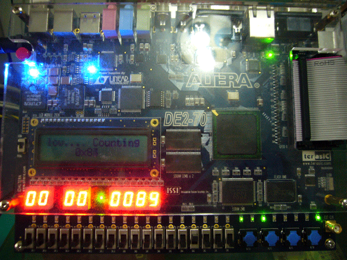
執行結果
完整程式碼下載
DE2_70_NIOS_count_binary.7z
Conclusion
在本文我們學到如何將Altera的project template移植到DE2-70上,事實上很多Altera原廠的範例,都是為Altera原廠開發版所設計,只要使用本文所提出的技巧,就能移植到DE2/DE2-70上執行。
See Also
(原創) 哪裡有DE2-70的Nios II reference design可以參考? (SOC) (DE2-70) (Nios II) (SOPC Builder)
(原創) 如何在Nios II顯示8位數的七段顯示器? (SOC) (Nios II) (SOPC Builder) (DE2-70)
Reference
Using SignalTap II Embedded Logic Analyzers in SOPC Builder Systems

 浙公网安备 33010602011771号