MIT6.828——Lab1 partA(麻省理工操作系统课程实验)
Lab1
基本部分
在实验给出的文档中,已经详说明了早期PC的内存布局,并且运行了bootloader。详细地解释了,上电后BIOS所做的工作,因此这部分不再赘述。需要注意的是bootloader的职能:
- 进入保护模式
- 从磁盘加载kernel到内存
boot/boot.S
实验文档中要求好好理解boot/boot.S和boot/main.c 。先看汇编文件
# Start the CPU: switch to 32-bit protected mode, jump into C.
# The BIOS loads this code from the first sector of the hard disk into
# memory at physical address 0x7c00 and starts executing in real mode
# with %cs=0 %ip=7c00.

.set PROT_MODE_CSEG, 0x8         # kernel code segment selector
.set PROT_MODE_DSEG, 0x10        # kernel data segment selector
.set CR0_PE_ON,      0x1         # protected mode enable flag

.globl start
start:
  .code16                     # Assemble for 16-bit mode
  cli                         # Disable interrupts
  cld                         # String operations increment
可以看到第一条被加载到0x7c00处的代码应该是cli关中断指令。之后进行了部分寄存器的初始化
# Set up the important data segment registers (DS, ES, SS).
  xorw    %ax,%ax             # Segment number zero
  movw    %ax,%ds             # -> Data Segment
  movw    %ax,%es             # -> Extra Segment
  movw    %ax,%ss             # -> Stack Segment
然后是开启A20地址线。早期8086处理器,只有20根地址线,因此编码时地址最高到0xfffff之后便会归零。然而在80286时期,地址线已经增长到24根,为了早期程序的兼容性,A20(第21根地址线)是默认关闭的。现在为了进入保护模式我们需要手动开启这根线。开启的方法是利用8042芯片的IO端口。
 # Enable A20:
  #   For backwards compatibility with the earliest PCs, physical
  #   address line 20 is tied low, so that addresses higher than
  #   1MB wrap around to zero by default.  This code undoes this.
seta20.1:
  inb     $0x64,%al               # Wait for not busy
  testb   $0x2,%al
  jnz     seta20.1

  movb    $0xd1,%al               # 0xd1 -> port 0x64
  outb    %al,$0x64

seta20.2:
  inb     $0x64,%al               # Wait for not busy
  testb   $0x2,%al
  jnz     seta20.2

  movb    $0xdf,%al               # 0xdf -> port 0x60
  outb    %al,$0x60
首先了解一下8042的状态寄存器
Bit7: PARITY-EVEN(P_E): 从键盘获得的数据奇偶校验错误
Bit6: RCV-TMOUT(R_T): 接收超时,置1
Bit5: TRANS_TMOUT(T_T): 发送超时,置1
Bit4: KYBD_INH(K_I): 为1,键盘没有被禁止。为0,键盘被禁止。
Bit3: CMD_DATA(C_D): 为1,输入缓冲器中的内容为命令,为0,输入缓冲器中的内容为数据。
Bit2: SYS_FLAG(S_F): 系统标志,加电启动置0,自检通过后置1
Bit1: INPUT_BUF_FULL(I_B_F): 输入缓冲器满置1,i8042 取走后置0
BitO: OUT_BUF_FULL(O_B_F): 输出缓冲器满置1,CPU读取后置0
然后便是端口地址,8042只使用两个端口
0x64 :命令端口
0x60 :数据端口
然后便是一些相关的命令,这里只选取和代码相关的:
驱动对键盘控制器发送命令是通过写端口64h实现:
D1h
准备写Output端口。随后通过60h端口写入的字节,会被放置在Output Port中。
关于向8042发送命令前的准备工作:
向i8042发命令的方法,首先,读取状态寄存器,判断bit1,状态寄存器bit1为0,说明输入缓冲器为空,可以写入。保证状态寄存器bit1为0,然后对64h端口进行写操作,写入命令。
那么这段代码就很明显了,至于0xdf解释如下
0xdd :disenable A20
0xdf :enable A20
至此A20便开启了。
下面是关于加载GDT的代码
# Switch from real to protected mode, using a bootstrap GDT
  # and segment translation that makes virtual addresses
  # identical to their physical addresses, so that the
  # effective memory map does not change during the switch.
  lgdt    gdtdesc
  movl    %cr0, %eax
  orl     $CR0_PE_ON, %eax
  movl    %eax, %cr0
  #......
  # Bootstrap GDT
.p2align 2                                # force 4 byte alignment
gdt:
  SEG_NULL				# null seg
  SEG(STA_X|STA_R, 0x0, 0xffffffff)	    # code seg
  SEG(STA_W, 0x0, 0xffffffff)	        # data seg
gdtdesc:
  .word   0x17                            # sizeof(gdt) - 1
  .long   gdt                             # address gdt
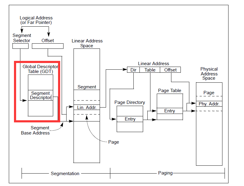
指令lgdt装载了gdt descriptor,其中的0x17是全局描述符表的大小,一共装载了3个段,每个段的大小是8字节,因此24字节。关于gdt可以看下图:
而对于这三个段的定义,需要结合#include <inc/mmu.h>
/*
 * Macros to build GDT entries in assembly.
 */
#define SEG_NULL						\
	.word 0, 0;						\
	.byte 0, 0, 0, 0
#define SEG(type,base,lim)					\
	.word (((lim) >> 12) & 0xffff), ((base) & 0xffff);	\
	.byte (((base) >> 16) & 0xff), (0x90 | (type)),		\
		(0xC0 | (((lim) >> 28) & 0xf)), (((base) >> 24) & 0xff)
//......
#define STA_X		0x8	    // Executable segment
#define STA_E		0x4	    // Expand down (non-executable segments)
#define STA_C		0x4	    // Conforming code segment (executable only)
#define STA_W		0x2	    // Writeable (non-executable segments)
#define STA_R		0x2	    // Readable (executable segments)
#define STA_A		0x1	    // Accessed
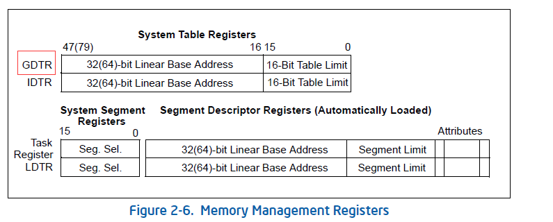
为了更好地理解,先看一下Intel手册中,关于保护模式下内存管理地描述(chapter3)。几个值得注意的点,一个是关于GDTR
这就是ldgt装载地寄存器,前文的代码含义便很清楚了。
下图是关于段的type

因此:
#define STA_X		0x8	    // Executable segment
#define STA_W		0x2	    // Writeable (non-executable segments)
#define STA_R		0x2	    // Readable (executable segments)
所以(STA_X|STA_R)便是type(1010),即可执行可读。
下图是关于segment descriptor
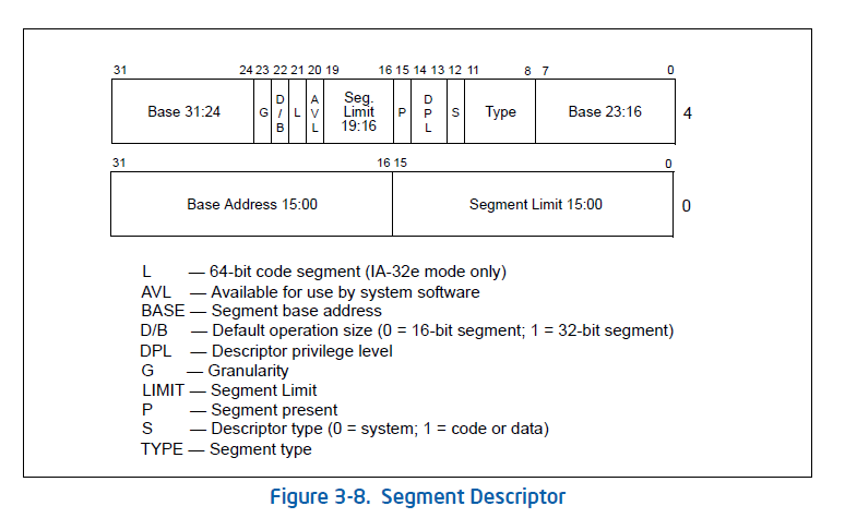
有几个域是我们感兴趣的:
Segment limit field
Specifies the size of the segment. The processor puts together the two segment limit fields to form a 20-bit value.
Base address fields
Defines the location of byte 0 of the segment within the 4-GByte linear address space. The processor puts together the three base address fields to form a single 32-bit value. Segment base addresses should be aligned to 16-byte boundaries. Although 16-byte alignment is not required,this alignment allows programs to maximize performance by aligning code and data on 16-byte boundaries.
Type field
Indicates the segment or gate type and specifies the kinds of access that can be made to the segment and the direction of growth.
S (descriptor type) flag
Specifies whether the segment descriptor is for a system segment (S flag is clear) or a code or data segment (S flag is set).
DPL (descriptor privilege level) field
Specifies the privilege level of the segment. The privilege level can range from 0 to 3, with 0 being the most privileged level.
P (segment-present) flag
Indicates whether the segment is present in memory (set) or not present (clear).
D/B (default operation size/default stack pointer size and/or upper bound) flag
Performs different functions depending on whether the segment descriptor is an executable code segment, an expand-down data segment, or a stack segment. (This flag should always be set to 1 for 32-bit code and data segments and to 0 for 16-bit code and data segments.)
L (64-bit code segment) flag
In IA-32e mode, bit 21 of the second doubleword of the segment descriptor indicates whether a code segment contains native 64-bit code. A value of 1 indicates instructions in this code segment are executed in 64-bit mode. A value of 0 indicates the instructions in this code segment are executed in compatibility mode.
G (granularity) flag
Determines the scaling of the segment limit field. When the granularity flag is clear, the segment limit is interpreted in byte units; when flag is set, the segment limit is interpreted in 4-KByte units. (This flag does not affect the granularity of the base address; it is always byte granular.) When the granularity flag is set, the twelve least significant bits of an offset are not tested when checking the offset against the segment limit. For example, when the granularity flag is set, a limit of 0 results in valid offsets from 0 to 4095.
这之后我们再去看代码,便很清晰了,以
SEG(STA_X|STA_R, 0x0, 0xffffffff) # code seg
为例子,先解读C语言的这段宏
#define SEG(type,base,lim)					\
	.word (((lim) >> 12) & 0xffff), ((base) & 0xffff);	\
	.byte (((base) >> 16) & 0xff), (0x90 | (type)),		\
		(0xC0 | (((lim) >> 28) & 0xf)), (((base) >> 24) & 0xff)
.word (((lim) >> 12) & 0xffff), ((base) & 0xffff)
获得了界限的bit12-27,共计16位。在(((lim) >> 28) & 0xf)中获得了最高4位。共计20位。因为要映射到完整的4G空间,也就是说,段限最大0xffffffff。因为后面置位了段描述符的G位,因此以4KB为单元就扩展到了最大段限制4G。
(0x90 | (type)),(0xC0 | (((lim) >> 28) & 0xf))
这里只需解释:
0x90 P=1(在内存中) DPL=00(特权级0) S=1(代码段或者数据段)
0xC0 G=1(4KB单位解释段限) D/B=1(32位代码应总是1) L=0 AVL=0
至此关于GDT的这段故事完结。
之后
movl    %cr0, %eax
orl     $CR0_PE_ON, %eax
movl    %eax, %cr0
先看关于CR0

CR0.PE
Protection Enable (bit 0 of CR0) — Enables protected mode when set; enables real-address mode when clear. This flag does not enable paging directly. It only enables segment-level protection. To enable paging, both the PE and PG flags must be set.
所以PE允许了保护模式的开启,并且开启了分段保护机制(没开启分页PG),这也就是为什么要在此之前建立GDT。至此,已经进入了32位的保护模式,因此寻址方式也已经发生变化。
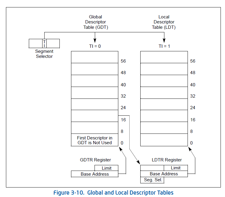
先了解段选择子

保护模式是通过“段选择符+段内偏移”寻址最终的线性地址或物理地址的。

TI位,选择GDT或者是LDT
因此
# Jump to next instruction, but in 32-bit code segment.
# Switches processor into 32-bit mode.
ljmp    $PROT_MODE_CSEG, $protcseg
段选择子就是$PROT_MODE_CSEG也就是0x8,即0000000000001 0 00
所以是GDT的第二项,基址为0x00000000,因此与之前的CS一致。
这里针对保护模式下的段选择子和段寄存器再多写一点[来自Intel手册Volume 3]。
为了减少地址转换用时和编码的复杂度,处理器提供6个段寄存器来保存段选择子。
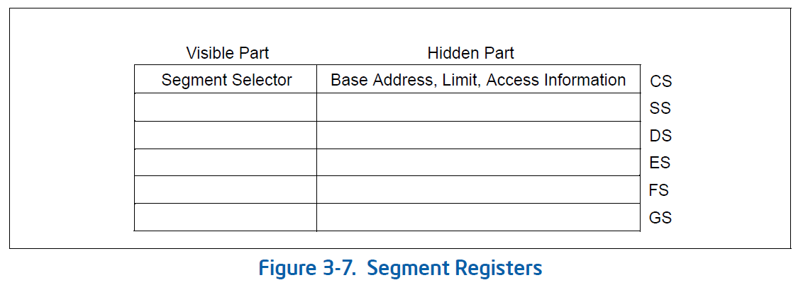
每个段寄存器都支持特定的内存寻址。对于任何程序的执行,至少要将CS,DS,SS赋予有效的段选择符。当一个进程需要访问某个段时,这个段的段选择子必须被赋予到某一个段寄存器中。因此,尽管可以定义很多段,但是只有6个能被直接使用。每个段寄存器都由两个部分组成,可见部分和不可见部分。当一个段选择子被加载到段寄存器的可见部分时,处理器也通过段选择符指向的段描述符获得了这个段的不可见信息。
有两种装入段寄存器的指令:
-
直接载入
movpopldsleslsslgs和lfs -
隐含地载入
far pointer 版本的
calljmpret指令,还有iretintnint0int3指令。伴随着这些指令的进行,他们改变了CS寄存器。
# Set up the stack pointer and call into C.
  movl    $start, %esp
  call bootmain
把栈顶设在了start处,也就是0x7c00,之后调用了C语言函数。
参考材料
[关于8042详细的解读]https://blog.csdn.net/wyyy2088511/article/details/108847079
[关于A20地址线]https://docs.huihoo.com/gnu_linux/own_os/booting-a20_4.htm
[关于0xdf]https://stackoverflow.com/questions/15768683/the-a20-line-with-jos
[关于A20与编程]https://www.win.tue.nl/~aeb/linux/kbd/A20.html
[GDT wiki]https://en.wikipedia.org/wiki/Global_Descriptor_Table
[lgdt]https://www.jianshu.com/p/2cb94c4c0cd0
[ucore]https://zhuanlan.zhihu.com/p/67259776
[CHAPTER 3 protected-mode]https://pdos.csail.mit.edu/6.828/2018/readings/ia32/IA32-3A.pdf
[ucore boot]https://www.cnblogs.com/maruixin/p/3175894.html
boot/main.c
先看一个比较简单的函数
void waitdisk(void)
{
	// wait for disk reaady
	while ((inb(0x1F7) & 0xC0) != 0x40)
		/* do nothing */;
}
端口1F7在被读的时候是作为状态寄存器使用,其中bit_7=0表示控制器空闲,bit_6=1表示驱动器就绪。因此,waitdisk在控制器空闲和驱动器就绪同时成立时才会结束等待。即在0100 0000时退出等待。
下面是一个读取扇区的函数
void readsect(void *dst, uint32_t offset)
{
	// wait for disk to be ready
	waitdisk();

	outb(0x1F2, 1);		// count = 1
	outb(0x1F3, offset);
	outb(0x1F4, offset >> 8);
	outb(0x1F5, offset >> 16);
	outb(0x1F6, (offset >> 24) | 0xE0);
	outb(0x1F7, 0x20);	// cmd 0x20 - read sectors

	// wait for disk to be ready
	waitdisk();

	// read a sector
	insl(0x1F0, dst, SECTSIZE/4);
}
首先
outb(port,data): 向port写入1字节数据data
insl(port,addr,cnt) : 从port读cnt个dword到addr中去
关于端口的含义,可以参考UCORE的实验教材

因此,这个函数从磁盘上读了SECTSIZE/4dword的数据,也就是512字节,刚好一个扇区。
下面一个函数,进行kernel的加载,一个辅助的函数是从磁盘读到内存中特定的地址上。
// Read 'count' bytes at 'offset' from kernel into physical address 'pa'.
// Might copy more than asked
void
readseg(uint32_t pa, uint32_t count, uint32_t offset)
{
	uint32_t end_pa;
	end_pa = pa + count;
	// round down to sector boundary
	pa &= ~(SECTSIZE - 1);

	// translate from bytes to sectors, and kernel starts at sector 1
	offset = (offset / SECTSIZE) + 1;

	// If this is too slow, we could read lots of sectors at a time.
	// We'd write more to memory than asked, but it doesn't matter --
	// we load in increasing order.
	while (pa < end_pa) {
		// Since we haven't enabled paging yet and we're using
		// an identity segment mapping (see boot.S), we can
		// use physical addresses directly.  This won't be the
		// case once JOS enables the MMU.
		readsect((uint8_t*) pa, offset);
		pa += SECTSIZE;
		offset++;
	}
}
在解释bootmain之前需要了解一下ELF文件格式
ELF文件(Executable Linkable Format)是一种文件存储格式。Linux下的目标文件和可执行文件都按照该格式进行存储。代码编译后的指令放在代码段,全局变量和局部静态变量放到数据段。文件以一个“文件头”开始,记录了整个文件的属性信息。
以下是inc/elf.h的部分
#define ELF_MAGIC 0x464C457FU	/* "\x7FELF" in little endian */

struct Elf {
	uint32_t e_magic;	// must equal ELF_MAGIC
	uint8_t e_elf[12];
	uint16_t e_type;
	uint16_t e_machine;
	uint32_t e_version;
	uint32_t e_entry;  //程序入口的虚地址
	uint32_t e_phoff;  //program header表的位置偏移
	uint32_t e_shoff;
	uint32_t e_flags;
	uint16_t e_ehsize;
	uint16_t e_phentsize;
	uint16_t e_phnum;  //program header表中的入口数目
	uint16_t e_shentsize;
	uint16_t e_shnum;
	uint16_t e_shstrndx;
};
//一个ELF文件中分为好几个段,程序段、数据段等
struct Proghdr {
	uint32_t p_type;	// 段类型
	uint32_t p_offset;  // 段相对文件头的偏移值
	uint32_t p_va;		// 段的第一个字节将被放到内存中的虚拟地址
	uint32_t p_pa;
	uint32_t p_filesz;
	uint32_t p_memsz;	// 段在内存映像中占用的字节数
	uint32_t p_flags;
	uint32_t p_align;
};
下面是bootmain的实现,关键部分给与注释
void
bootmain(void)
{
    //两个program header指针
	struct Proghdr *ph, *eph;

    //磁盘第一个页读到内存位置0x10000的位置
    //页大小512*8=4kB 偏移量为0
	// read 1st page off disk
	readseg((uint32_t) ELFHDR, SECTSIZE*8, 0);

	// is this a valid ELF?
	if (ELFHDR->e_magic != ELF_MAGIC)
		goto bad;

    // 程序头表的头指针,为ELF文件的起始地址加上程序头表的偏移量
	// load each program segment (ignores ph flags)
	ph = (struct Proghdr *) ((uint8_t *) ELFHDR + ELFHDR->e_phoff);

    // 程序头表的尾指针,为ELF文件的头指针加上程序头表的段数
	eph = ph + ELFHDR->e_phnum;

	for (; ph < eph; ph++)
        //循环读取ELF程序头表中的每个段(代码段,数据段)到内存中
		// p_pa is the load address of this segment (as well
		// as the physical address)
        // pa物理地址 memsz占用的字节 offset偏移
		readseg(ph->p_pa, ph->p_memsz, ph->p_offset);
	//至此内核就加载完成了,马上移交控制权
	// call the entry point from the ELF header
	// note: does not return!
    // 跳转到内核程序的入口,CPU 控制权交给kernel,不再返回
    // 内核代码会被加载到指定位置,都会以一个ELF格式开头,以此可以得到入口地址
	((void (*)(void)) (ELFHDR->e_entry))();
bad:
	outw(0x8A00, 0x8A00);
	outw(0x8A00, 0x8E00);
	while (1)
		/* do nothing */;
}
至此,bootloader的程序代码已经没有秘密了,是一个很底层的过程,但对于了解计算机启动的初始阶段很有帮助。
下一篇文章,包括kernel部分与lab1的习题。
参考文章
[ports]https://bochs.sourceforge.io/techspec/PORTS.LST
[ucore ports]https://chyyuu.gitbooks.io/ucore_os_docs/content/lab1/lab1_3_2_3_dist_accessing.html
[insl]https://stackoverflow.com/questions/38410829/why-cant-find-the-insl-instruction-in-x86-document
[ucore elf]https://chyyuu.gitbooks.io/ucore_os_docs/content/lab1/lab1_3_2_4_elf.html

 浙公网安备 33010602011771号