华为S5700系列交换机配置通过流策略实现VLAN间三层隔离
组网图形
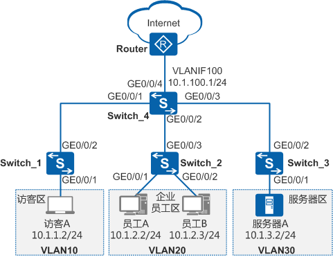
图1 配置通过流策略实现VLAN间三层隔离组网图
1|0组网需求
如图一所示,为了通信的安全性,某公司将访客、员工、服务器分别划分到VLAN10、VLAN20、VLAN30中。公司希望:
- 员工、服务器主机、访客均能访问Internet。
- 访客只能访问Internet,不能与其他任何VLAN的用户通信。
- 员工A可以访问服务器区的所有资源,但其他员工只能访问服务器A的21端口(FTP服务)。
2|0配置思路
可采用如下思路配置通过流策略实现VLAN间互访控制:
1. 配置VLAN并将各接口加入VLAN,使员工、服务器、访客间二层隔离。
2. 配置VLANIF接口及其IP地址,使员工、服务器、访客间可三层互通。
3. 配置上行路由,使员工、服务器、访客均可通过Switch访问Internet。
4. 配置并应用流策略,使员工A可以访问服务器区的所有资源,其他员工只能访问服务器A的21端口,且只允许员工访问服务器;使访客只能访问Internet。
3|0操作步骤
1. 配置VLAN并将各接口加入VLAN,使员工、服务器、访客间二层隔离
# 在Switch_1上创建VLAN10,并将接口GE0/0/1以Untagged方式加入VLAN10,接口GE0/0/2以Tagged方式加入VLAN10。Switch_2和Switch_3的配置与Switch_1类似,不再赘述。
|
1
2
3
4
5
6
7
8
9
10
11
|
<HUAWEI> system-view[HUAWEI] sysname Switch_1[Switch_1] vlan batch 10[Switch_1] interface gigabitethernet 0/0/1[Switch_1-GigabitEthernet0/0/1] port link-type access[Switch_1-GigabitEthernet0/0/1] port default vlan 10[Switch_1-GigabitEthernet0/0/1] quit[Switch_1] interface gigabitethernet 0/0/2[Switch_1-GigabitEthernet0/0/2] port link-type trunk[Switch_1-GigabitEthernet0/0/2] port trunk allow-pass vlan 10[Switch_1-GigabitEthernet0/0/2] quit |
# 在Switch_4上创建VLAN10、VLAN20、VLAN30、VLAN100,并配置接口GE0/0/1~GE0/0/4分别以Tagged方式加入VLAN10、VLAN20、VLAN30、VLAN100。
|
1
2
3
4
5
6
7
8
9
10
11
12
13
14
15
16
17
18
19
|
<HUAWEI> system-view[HUAWEI] sysname Switch_4[Switch_4] vlan batch 10 20 30 100[Switch_4] interface gigabitethernet 0/0/1[Switch_4-GigabitEthernet0/0/1] port link-type trunk[Switch_4-GigabitEthernet0/0/1] port trunk allow-pass vlan 10[Switch_4-GigabitEthernet0/0/1] quit[Switch_4] interface gigabitethernet 0/0/2[Switch_4-GigabitEthernet0/0/2] port link-type trunk[Switch_4-GigabitEthernet0/0/2] port trunk allow-pass vlan 20[Switch_4-GigabitEthernet0/0/2] quit[Switch_4] interface gigabitethernet 0/0/3[Switch_4-GigabitEthernet0/0/3] port link-type trunk[Switch_4-GigabitEthernet0/0/3] port trunk allow-pass vlan 30[Switch_4-GigabitEthernet0/0/3] quit[Switch_4] interface gigabitethernet 0/0/4[Switch_4-GigabitEthernet0/0/4] port link-type trunk[Switch_4-GigabitEthernet0/0/4] port trunk allow-pass vlan 100[Switch_4-GigabitEthernet0/0/4] quit |
2. 配置VLANIF接口及其IP地址,使员工、服务器、访客间可以三层互通
# 在Switch_4上创建VLANIF10、VLANIF20、VLANIF30、VLANIF100,并分别配置其IP地址为10.1.1.1/24、10.1.2.1/24、10.1.3.1/24、10.1.100.1/24。
|
1
2
3
4
5
6
7
8
9
10
11
12
|
[Switch_4] interface vlanif 10[Switch_4-Vlanif10] ip address 10.1.1.1 24[Switch_4-Vlanif10] quit[Switch_4] interface vlanif 20[Switch_4-Vlanif20] ip address 10.1.2.1 24[Switch_4-Vlanif20] quit[Switch_4] interface vlanif 30[Switch_4-Vlanif30] ip address 10.1.3.1 24[Switch_4-Vlanif30] quit[Switch_4] interface vlanif 100[Switch_4-Vlanif100] ip address 10.1.100.1 24[Switch_4-Vlanif100] quit |
3. 配置上行路由,使员工、服务器、访客均可通过Switch访问Internet。
# 在Switch_4上配置OSPF基本功能,发布用户网段以及Switch_4与Router之间的互联网段。
|
1
2
3
4
5
6
7
8
|
[Switch_4] ospf[Switch_4-ospf-1] area 0[Switch_4-ospf-1-area-0.0.0.0] network 10.1.1.0 0.0.0.255[Switch_4-ospf-1-area-0.0.0.0] network 10.1.2.0 0.0.0.255[Switch_4-ospf-1-area-0.0.0.0] network 10.1.3.0 0.0.0.255[Switch_4-ospf-1-area-0.0.0.0] network 10.1.100.0 0.0.0.255[Switch_4-ospf-1-area-0.0.0.0] quit[Switch_4-ospf-1] quit |
说明:
Router上需要进行如下配置:
- 将连接Switch的接口以Tagged方式加入VLAN100,并指定VLANIF100的IP地址与10.1.100.1在同一网段。
- 配置OSPF基本功能,并发布Switch与Router之间的互联网段。
具体配置请参见使用设备的产品文档,本文不再赘述。
4. 配置并应用流策略,控制员工、访客、服务器之间的访问
a. 通过ACL定义每个流
# 在Switch_4上配置ACL 3000,禁止访客访问员工区和服务器区。
|
1
2
3
4
|
[Switch_4] acl 3000[Switch_4-acl-adv-3000] rule deny ip destination 10.1.2.1 0.0.0.255[Switch_4-acl-adv-3000] rule deny ip destination 10.1.3.1 0.0.0.255[Switch_4-acl-adv-3000] quit |
# 在Switch_4上配置ACL 3001,使员工A可以访问服务器区的所有资源,其他员工只能访问服务器A的21端口。
|
1
2
3
4
5
|
[Switch_4] acl 3001[Switch_4-acl-adv-3001] rule permit ip source 10.1.2.2 0 destination 10.1.3.1 0.0.0.255[Switch_4-acl-adv-3001] rule permit tcp destination 10.1.3.2 0 destination-port eq 21[Switch_4-acl-adv-3001] rule deny ip destination 10.1.3.1 0.0.0.255[Switch_4-acl-adv-3001] quit |
b. 配置流分类,区分不同的流
# 在Switch_4上创建流分类c_custom、c_staff,并分别配置匹配规则3000、3001。
|
1
2
3
4
5
6
|
[Switch_4] traffic classifier c_custom[Switch_4-classifier-c_custom] if-match acl 3000[Switch_4-classifier-c_custom] quit[Switch_4] traffic classifier c_staff[Switch_4-classifier-c_staff] if-match acl 3001[Switch_4-classifier-c_staff] quit |
c. 配置流行为,指定流动作
# 在Switch_4上创建流行为b1,并配置允许动作。
|
1
2
3
|
[Switch_4] traffic behavior b1[Switch_4-behavior-b1] permit[Switch_4-behavior-b1] quit |
d. 配置流策略,关联流分类和流行为
# 在Switch_4上创建流策略p_custom、p_staff,并分别将流分类c_custom、c_staff与流行为b1关联。
|
1
2
3
4
5
6
|
[Switch_4] traffic policy p_custom[Switch_4-trafficpolicy-p_custom] classifier c_custom behavior b1[Switch_4-trafficpolicy-p_custom] quit[Switch_4] traffic policy p_staff[Switch_4-trafficpolicy-p_staff] classifier c_staff behavior b1[Switch_4-trafficpolicy-p_staff] quit |
e. 应用流策略,实现员工、访客、服务器之间的访问控制
# 在Switch_4上,分别在VLAN10、VLAN20的入方向应用流策略p_custom、p_staff。
|
1
2
3
4
5
6
|
[Switch_4] vlan 10[Switch_4-vlan10] traffic-policy p_custom inbound[Switch_4-vlan10] quit[Switch_4] vlan 20[Switch_4-vlan20] traffic-policy p_staff inbound[Switch_4-vlan20] quit |
5. 验证配置结果
配置访客A的IP地址为10.1.1.2/24,缺省网关为VLANIF10接口的IP地址10.1.1.1;配置员工A的IP地址为10.1.2.2/24,缺省网关为VLANIF20接口的从IP地址10.1.2.1;配置员工B的IP地址为10.1.2.3/24,缺省网关为VLANIF20接口的从IP地址10.1.2.1;配置服务器A的IP地址为10.1.3.2/24,缺省网关为VLANIF30接口的从IP地址10.1.3.1。
配置完成后:
- 访客A不能Ping通员工A、服务器A;员工A和服务器A不能Ping通访客A。
- 员工A可以Ping通服务器A,即可以使用服务器A的FTP服务,也可以使用服务器A的。
- 员工B可以Ping不通服务器A,只能使用服务器A的FTP服务。
- 访客、员工A、员工B、服务器A均可以Ping通Router连接Switch_4的接口的IP地址10.1.100.2/24,也就都可以访问Internet。
- Switch_1的配置文件
4|0配置文件
|
1
2
3
4
5
6
7
8
9
10
11
12
13
14
|
#sysname Switch_1#vlan batch 10#interface GigabitEthernet0/0/1 port link-type access port default vlan 10#interface GigabitEthernet0/0/2 port link-type trunk port trunk allow-pass vlan 10#return |
Switch_2的配置文件
|
1
2
3
4
5
6
7
8
9
10
11
12
13
14
15
16
17
18
|
#sysname Switch_2#vlan batch 20#interface GigabitEthernet0/0/1 port link-type access port default vlan 20#interface GigabitEthernet0/0/2 port link-type access port default vlan 20#interface GigabitEthernet0/0/3 port link-type trunk port trunk allow-pass vlan 20#return |
Switch_3的配置文件
|
1
2
3
4
5
6
7
8
9
10
11
12
13
14
|
#sysname Switch_3#vlan batch 30#interface GigabitEthernet0/0/1 port link-type access port default vlan 30#interface GigabitEthernet0/0/2 port link-type trunk port trunk allow-pass vlan 30#return |
Switch_4的配置文件
|
1
2
3
4
5
6
7
8
9
10
11
12
13
14
15
16
17
18
19
20
21
22
23
24
25
26
27
28
29
30
31
32
33
34
35
36
37
38
39
40
41
42
43
44
45
46
47
48
49
50
51
52
53
54
55
56
57
58
59
60
61
62
63
64
65
66
67
|
#sysname Switch_4#vlan batch 10 20 30 100#acl number 3000 rule 5 deny ip destination 10.1.2.0 0.0.0.255 rule 10 deny ip destination 10.1.3.0 0.0.0.255acl number 3001 rule 5 permit tcp destination 10.1.3.2 0 destination-port eq ftp rule 10 permit ip source 10.1.2.2 0 destination 10.1.3.0 0.0.0.255 rule 15 deny ip destination 10.1.3.0 0.0.0.255#traffic classifier c_custom operator and if-match acl 3000traffic classifier c_staff operator and if-match acl 3001#traffic behavior b1 permit#traffic policy p_custom match-order config classifier c_custom behavior b1traffic policy p_staff match-order config classifier c_staff behavior b1#vlan 10 traffic-policy p_custom inboundvlan 20 traffic-policy p_staff inbound#interface Vlanif10 ip address 10.1.1.1 255.255.255.0#interface Vlanif20 ip address 10.1.2.1 255.255.255.0#interface Vlanif30 ip address 10.1.3.1 255.255.255.0#interface Vlanif100 ip address 10.1.100.1 255.255.255.0#interface GigabitEthernet0/0/1 port link-type trunk port trunk allow-pass vlan 10#interface GigabitEthernet0/0/2 port link-type trunk port trunk allow-pass vlan 20#interface GigabitEthernet0/0/3 port link-type trunk port trunk allow-pass vlan 30#interface GigabitEthernet0/0/4 port link-type trunk port trunk allow-pass vlan 100#ospf 1 area 0.0.0.0 network 10.1.1.0 0.0.0.255 network 10.1.2.0 0.0.0.255 network 10.1.3.0 0.0.0.255 network 10.1.100.0 0.0.0.255#return |

 浙公网安备 33010602011771号