I2C传输协议介绍
| 日期 | 版本 | 内容修改 |
|---|---|---|
| 2023/03/11 | V0 | 初版 |
| 2024/03/15 | V1 | 增加了I2C传输大小端的说明 |
| 2024/03/21 | V2 | 增加了关于I2C标准速率的理解,增加了I2C上拉的解释 |
1. I2C协议
I2C协议由Philips公司推出。
1.1. 端口名称及含义
标准I2C只有2根信号线。
-
SCL
Serial CLock:串行时钟线,由主机产生并分享给从机。
-
SDA
Serial DAta:串行数据线,连接在主从机之间。把发送信号的一方叫做发送机,接收信号的叫做接收机。发送/接收机是随时改变的。
I2C仅有两根线,比SPI要简单得多。但是其代价为,SDA线的通信格式比较复杂,且相对固定。
1.2. 传输协议格式[1]
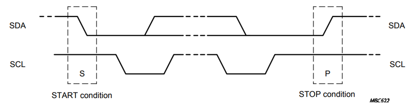
1.2.1. 起始(S)和终止条件(P)
一般不区分起始条件和重复起始条件(S和Sr)。S和P的定义如下图。
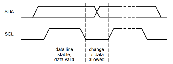
1.2.2. 有效信号时间
如果在SCL=1期间SDA变动,那么必然是S/P,如果想要传输完整的信号,那么信号在SCL=1期间必须保持稳定,只能在SCL=0期间变化。
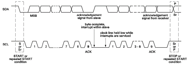
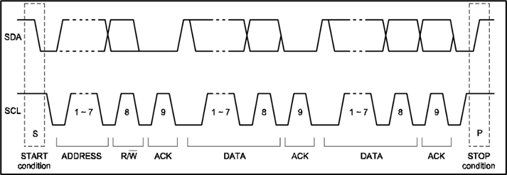
1.3. 传输格式
SDA线上传输的每次必须为一个字节的信息,可以传输多个字节。一个字节的信息可以是从机地址或者传输的信息。在每个字节的信息后都跟着从机的一位应答信号(ACK或A,从机拉低低信号为有效应答)。注意,在数据位,主机控制了SDA线;但在最后一位应答位时,发送机必须放出SDA线,让接收机去控制,如果接收机成功地拉低了,就说明接收机成功响应了。
I2C协议先传输MSB。或者说,I2C是big endian传输的。
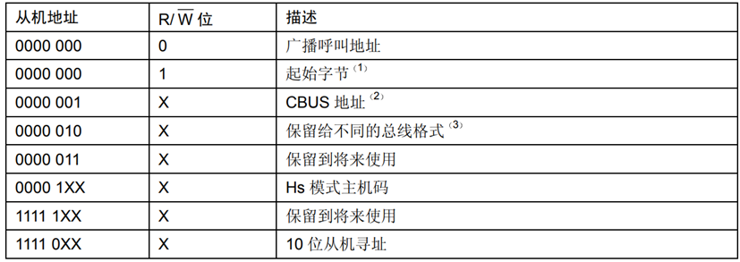
在完整的传输过程中,第一个字节一般是 “主机发送7位地址+主机发送R/W+从机Ack” 的格式,如下图所示。
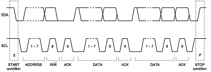
其中第一个字节的七位具有一些预留的格式。这些预留的格式保证了I2C可以与CBUS协议兼容。
1.4. 多个主机连接时的线与机制
I2C要求连接到总线的接口输出端都为OD门(MOS工艺)或OC门(BJT工艺)。比如下图是OD门连接方式。
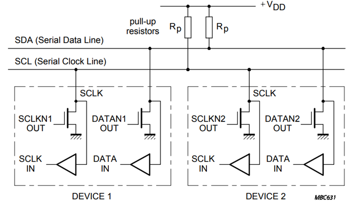
在OD门连接中,先假设只有一个主机连接,即输出端为 “上拉电阻+NMOS” 的组合,那么其输出必然是:
- NMOS开通,输出被拉低到0。
- NMOS关断,输出被电阻上拉到1。
现在再考虑多个主机连接的情况,一旦有一个NMOS开通,那么其他的NMOS管即使关断也没有用,电平一样会被拉下来,也就是 “输出只要有一个低,那么结果就是低” ,构成了 “线与” 的功能。这个线与功能是I2C完成仲裁的基础。
当然,这里只是从理论上描述一下I2C的OD门运行机制。具体还要看芯片的制造工艺、芯片管脚的电路模型等等。
1.5. 多主机连接时的仲裁机制
多个主机申请控制时的仲裁机制:
1.5.1. 多个主机的时钟同步
首先是多个主机的时钟如何同步。因为各个主机在SCL上也是用线与连接的,所以SCL的高低是可以确定的。
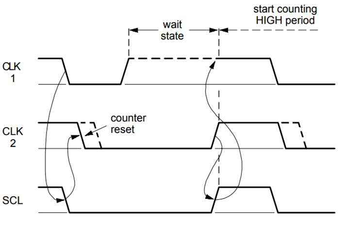
产生的同步SCL时钟的低电平周期由低电平时钟周期最长的器件决定,而高电平周期由高电平时钟周期最短的器件决定。比如在上图中,即使CLK1先达到了高,但是因为SCL未到达高,因此CLK1需要等待至SCL变高,然后开始计时高电平时间,这样几个周期下来就完成了时钟同步。
1.5.2. 主机申请数据传输时的仲裁机制
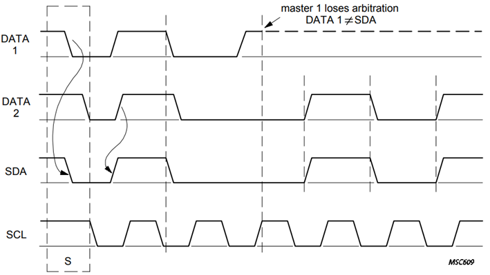
如下图是SCL相同时的SDA仲裁。在DATA2还处于低电平的时候,DATA1率先到达高,因此其丢失仲裁。丢失仲裁后,DATA1的输出级与SDA暂时断开,以免影响到DATA2的传输。
1.6. I2C的Verilog代码实现[2]
I2C代码来自Copyright (C) 2008 Steve Fielding and OPENCORES.ORG。
其基本思想是:利用一个时钟周期远小于SDA、SCL变化的时钟clk的边沿作为判断时刻。将整个I2C接口分为两个功能模块:串行传输线SCL和SDA信号的处理(serialInterface)、接收到SDA信号后存进移位寄存器完成串并转换的过程(registerInterface)。
真正困难的是如何读取SDA线上的信号,代码module名称为serialInterface.v,其思想是把每个可能性都转化为三段式状态机,根据状态机的流转,去做到 “判断开始/结束”“读数据”“Ack/NAck” 等功能。
1.6.1. 关于I2C SDA总线在芯片中的Pad的解释
I2C的SDA端口是一个双向接口,但是在芯片中,SDA只是一个Pad(意即只有一个管脚)。因此在芯片的输出管脚附近需要类似三态门的特殊的结构来让两个方向的信号互不干扰。
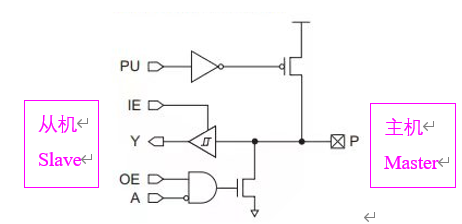
如上图所示,P是Pad,A是sdaOut,Y是sdaIn,PU是上拉使能,PU==1时允许上拉到电源。IE、OE本为输入/输出使能,但这里全部接高(即一直使能)。
如果从机希望把sda总线放掉,那么sdaOut必须在从机端口就被切断。如图中,当sdaOut<=0时,NMOS打开,输出被拉低,输出为0;当sdaOut<=1时,NMOS关闭,输出被PMOS拉高,为1。但是注意,此时的1是被电源和上拉电阻拉高的,因此可以再被拉低。这也就是说,只要sdaOut==1,sdaOut与SDA总线就是断开的。
如果需要多个从机,那么需要保证多个从机总共只有一个PU使能(OD门接法)。
关于sdaIn和sdaOut的关系,还可以从OD门的“线与”逻辑理解:
下面很多代码以此为基础。这也是代码中始终没有出现过z高阻的理由。
以上说的是芯片中的一种特殊Pad。如果芯片没有用这种特殊Pad,那么就需要外挂上拉电阻。
因此使用I2C器件时一定注意查看Datasheet,确定是否需要上拉电阻。一种常见的上拉方式是:上拉4.7 K电阻到3.3 V电压。
1.6.2. serialInterface的流程图和代码解释
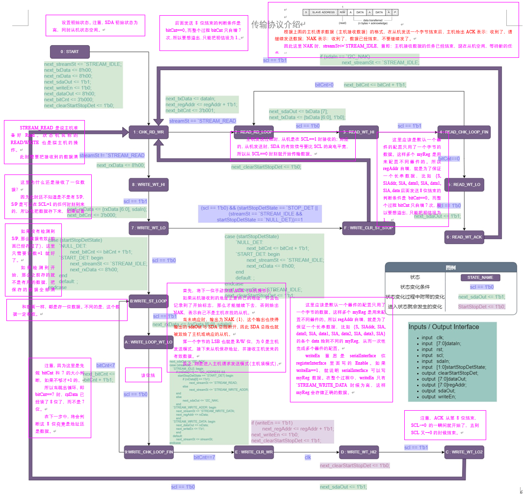
serialInterface.v就是控制从机对于SDA线的接收和发送。要接收或者发送的数据都暂存在register里面,由registerInterface控制传给serialInterface处理。
1.6.3. registerInterface的解释
控制着多个寄存器,这些寄存器每个都是一字节。寄存器的数量是不限制的,但是寄存器太多,地址就会变长,也会占用空间。对于本实验,甚至一个寄存器就足够了。
1.6.4. i2cSlave的连接和部分代码解释
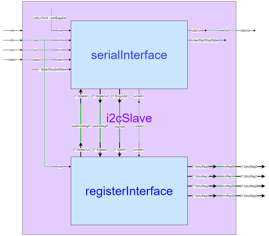
以上是各个模块的连接方式。
此外,i2cSlave还有一些其它功能,比如说考虑实际延迟而做出的校正,比如对S/P的判断。下面解释一些代码块。
1.6.4.1. i2cSlave.v接口
点击查看代码
registerInterface u_registerInterface(
  .clk(clk),
  .addr(regAddr),
  .dataIn(dataToRegIF),
  .writeEn(writeEn),
  .dataOut(dataFromRegIF),
  .myReg0(myReg0),
  .myReg1(myReg1),
  .myReg2(myReg2),
  .myReg3(myReg3)
);

serialInterface u_serialInterface (
  .clk(clk),
  .rst(rstSyncToClk | startEdgeDet),
  .dataIn(dataFromRegIF),
  .dataOut(dataToRegIF),
  .writeEn(writeEn),
  .regAddr(regAddr),
  .scl(sclDelayed[`SCL_DEL_LEN-1]),
  .sdaIn(sdaDeb),
  .sdaOut(sdaOut),
  .startStopDetState(startStopDetState),
  .clearStartStopDet(clearStartStopDet)
);
1.6.4.2. rst复位功能
点击查看代码
// sync rst rising edge to clk
always @(posedge clk) begin
  if (rst == 1'b1)
    rstPipe <= 2'b11;
  else
    rstPipe <= {rstPipe[0], 1'b0};
end

assign rstSyncToClk = rstPipe[1];
    //rstPipe will change as the order : {2'b00,11,10,00}
    //and the changes always happen on posedge clk.
    //That means, rstSyncToClk will always be high at the
    //second posedge clk, and that ensures the reset.
rst并不是一直使得电路reset的。如果rst保持很长时间的1,那么也只会复位一次。
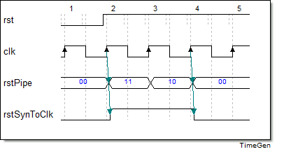
容易画出电路的时序图。可以发现,rstSynToClk只在至多两个posedge clk时刻保持了高电平。这使得电路能够复位,但又不会在rst信号不撤去的时候一直复位导致电路无法运行。
1.6.4.3. debounce防抖逻辑
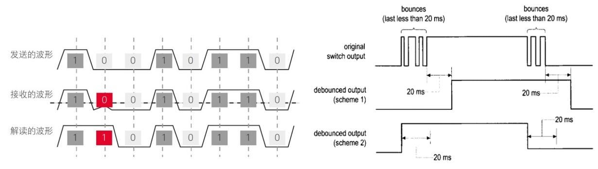
抖动,就是指上升/下降沿的时刻出现偏差。
根据代码i2cSlave_define.v的解释:
The rise time of SCL and SDA can be up to 1000ns (in standard mode), so it is essential to debounce the inputs.
也就是说,SCL和SDA的沿时间太长了,这使得在边沿变化过程中也可能遇到posedge clk,从而容易出现错误。我们希望在SCL/SDA的电平稳定了之后再进行采样。
debounce电路,就是常说的去抖滤波,主要用在芯片的PAD输入信号,或者模拟电路输出给数字电路的信号上。在本实验中,即SCL和SDA。
点击查看代码
// debounce sda and scl
always @(posedge clk) begin
  if (rstSyncToClk == 1'b1) begin
    sdaPipe <= {`DEB_I2C_LEN{1'b1}};
    sdaDeb <= 1'b1;
    sclPipe <= {`DEB_I2C_LEN{1'b1}};
    sclDeb <= 1'b1;
  end
  else begin
    sdaPipe <= {sdaPipe[`DEB_I2C_LEN-2:0], sdaIn};
    sclPipe <= {sclPipe[`DEB_I2C_LEN-2:0], scl};
    if (&sclPipe[`DEB_I2C_LEN-1:1] == 1'b1)
      sclDeb <= 1'b1;
    else if (|sclPipe[`DEB_I2C_LEN-1:1] == 1'b0)
      sclDeb <= 1'b0;
    if (&sdaPipe[`DEB_I2C_LEN-1:1] == 1'b1)
      sdaDeb <= 1'b1;
    else if (|sdaPipe[`DEB_I2C_LEN-1:1] == 1'b0)
      sdaDeb <= 1'b0;
  end
end
显然,debounce只有在信号电平变化之时才需要。在代码中,设立一个reg,称作xxxPipe,预设全为1。然后该数字序列会随着时钟一直刷新,直到整个序列变得一致为止,这说明电平已经稳定了。
而xxxDeb代表了debounce后给出的电平判断结果。
1.6.4.4. 信号延时
点击查看代码
// delay scl and sda
// sclDelayed is used as a delayed sampling clock
// sdaDelayed is only used for start stop detection
// Because sda hold time from scl falling is 0nS
// sda must be delayed with respect to scl to avoid incorrect
// detection of start/stop at scl falling edge.
always @(posedge clk) begin
  if (rstSyncToClk == 1'b1) begin
    sclDelayed <= {`SCL_DEL_LEN{1'b1}};
    sdaDelayed <= {`SDA_DEL_LEN{1'b1}};
  end
  else begin
    sclDelayed <= {sclDelayed[`SCL_DEL_LEN-2:0], sclDeb};
    sdaDelayed <= {sdaDelayed[`SDA_DEL_LEN-2:0], sdaDeb};
  end
end
延时的道理很简单,把debounce后的信号电平放到序列的最后一位,随着时间逐渐左移,这样就完成了延时。
在i2cSlave_define.v文件中,可以看到: \(t_{debounce}=t_{delay,scl}=2.5t_{delay,sda}\)
正如代码注释所说,scl做延时是为了比sda延时更多;sda做延时是为了检测S/P。在scl和sda都进行了debounce之后,波形如图下图所示:
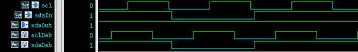
原来sda的边沿与scl边沿可能贴得很近,但是由于不同的延时,sclDeb和sdaDeb的边沿差距很大,这样S/P的判断就很难出现错误了。
1.6.4.5. 判断S/P
点击查看代码
// start stop detection
always @(posedge clk) begin
  if (rstSyncToClk == 1'b1) begin
    startStopDetState <= `NULL_DET;
    startEdgeDet <= 1'b0;
  end
  else begin
    if (sclDeb == 1'b1 && sdaDelayed[`SDA_DEL_LEN-2] == 1'b0
      && sdaDelayed[`SDA_DEL_LEN-1] == 1'b1)
      startEdgeDet <= 1'b1;
    else
      startEdgeDet <= 1'b0;
    if (clearStartStopDet == 1'b1)
      startStopDetState <= `NULL_DET;
    else if (sclDeb == 1'b1) begin
      if (sdaDelayed[`SDA_DEL_LEN-2] == 1'b1
        && sdaDelayed[`SDA_DEL_LEN-1] == 1'b0)
        startStopDetState <= `STOP_DET;
      else if (sdaDelayed[`SDA_DEL_LEN-2] == 1'b0
        && sdaDelayed[`SDA_DEL_LEN-1] == 1'b1)
        startStopDetState <= `START_DET;
    end
  end
end
因为给serialInterface的rst=rstSynToClk | startEdgeDet,所以在startEdgeDet<=1时serialInterface会reset,从机状态置为START。
i2cSlave_define.v注释:
SDA should have a minimum of 100ns of set up time, with respect to SCL rising edge. But with the very slow edge speeds used in I2C it is better to err on the side of caution.
i2cSlave.v注释:
Because sda hold time from scl falling is 0ns, sda must be delayed with respect to scl to avoid incorrect detection of start/stop at scl falling edge.
在sclDeb==1时可以检测S/P。假如说主机给入的是上图所示的信号,那么在SCL下降时刻SDA基本也就开始变化了,因此这样不太稳妥,容易导致在SCL为高有效时采不到正确的数据。因此,在I2C从机内部把SCL延迟地比SDA多一些,就会解决这个问题。
同时因为SDA信号被寄存器存下来了,因此后面可以慢慢用来判断S/P,而不用担心边沿过去了。
1.6.5. i2cSlaveTop的解释
i2cSlaveTop.v就是完全把i2cSlave的功能封装起来。除了I/O配置、实例运用,没有加入新的功能。
1.6.6. 代码的Verilog仿真
在仿真中,认为方波边沿时间为0,对于数字电路,这个假设是合理的,因此后面的仿真一直如此。
在实际的芯片配置和PCB连接中,sdaIn和sdaOut是用OD门连在一起的。但是在代码仿真里不需要考虑这些,它们是完全独立的信号。
进行代码仿真(Xilinx Vivado):
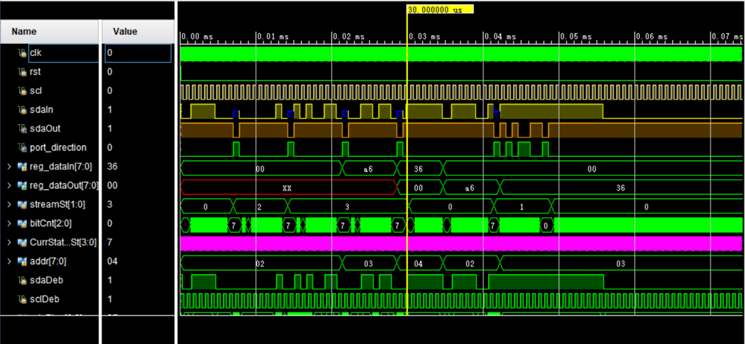
在图中,sdaIn==1’bz的时间是等待从机Ack的时间(虽然因为两条线是分开的,sdaIn是多少其实无所谓的,不过用来区分开每个字节也不错)。
可以看到,内容依次为:
| 传输位数 | 传输的方向以及字节内容 | 传输代表的意义 |
|---|---|---|
| / | scl=1期间,sdaIn下降 | S(开始信号) |
| 8 | 主机向从机写0111_1000 | 主机寻从机址011_1100(7’h3c),R/W=0(W) |
| 1 | 主机等待从机应答 | 从机给出应答Ack |
| 8 | 主机向从机写0000_0010 | 主机寻寄存器址0000_0010(8’h02),即myReg02 |
| 1 | 主机等待从机应答 | 从机给出应答Ack |
| 8 | 主机向从机写1010_0110 | 主机向从机寄存器myReg02写数据1010_0110 |
| 1 | 主机等待从机应答 | 从机给出应答Ack |
| 8 | 主机向从机写0011_0110 | 主机向从机寄存器myReg03写数据0011_0110 |
| 1 | 主机等待从机应答 | 从机给出应答Ack |
| / | scl=1期间,sdaIn上升 | P(结束信号) |
| 不限 | 无 | 任务结束,从机空闲 |
| / | scl=1期间,sdaIn下降 | S(开始信号) |
| 8 | 主机向从机写0111_1000 | 主机寻从机址011_1100(7’h3c),R/W=0(W) |
| 1 | 主机等待从机应答 | 从机给出应答Ack |
| 8 | 从机向主机写1010_0110 | 从机向主机发送myReg02数据(Addr复位时默认置8’h02) |
| 1 | 从机等待主机应答 | 主机给出不应答Nak,代表从机发送终止 |
注意:后面即使再用主机给出Ack去尝试激活从机继续发送数据,那也没用了。从机发送被主机终止,这个任务就已经结束了,只是主机还没有给出结束信号。
可以大概计算一下各信号宽度。I2C标准的传输速率为100 Kb/s(S)、400 Kb/s(F)、3.4 Mb/s(Hs),其实传输速率指的就是SCL时钟频率,因为每个SCL周期传输1 bit数据,分别计算其每位宽度为10 μs、2.5 μs、294.12 ns。在图示代码中用200ns作scl半周期,运行完全没有问题,因为clk半周期设为5 ns,相比与scl、sda来说太小了。所以速率的问题应该不用担心。
标准传输速率其实表示的只是芯片能容许的最大SCL传输速率,如果实际SCL速率比标称速率高就可能无法正常传输,因为此时可能不满足时钟clk频率远大于SCL频率这一条件。实际上,SCL总是由主机提供给从机,所以只要从机的标称速率能达到主机提供的SCL速率,从机接收(接收数据也是主机给的,必然与SCL速率吻合)或发送的数据率都能匹配SCL速率。
I2C标准的clk时钟频率好像没有标准的要求,只要比SCL、SDA频率高得多即可。为了和整个芯片的200 MHz内置频率匹配,可采用四分频,即50MHz的频率,也比较接近。经过测试,在20ns的clk周期下,scl周期设为1 μs,是完全没有问题的。一般I2C传输速率都在 百K~几M 频率范围内,而提供给从机模块的时钟最小也有几十MHz,因此此模块在任何情况下基本都能工作。
这里I2C也不太纠结速率,也不太纠结速率是否标准,因此上述数据就可以了。
2. 附录:I2C完整Verilog代码
2.1. timescale.v
点击查看代码
//////////////////////////////////////////////////////////////////////
// timescale.v
//////////////////////////////////////////////////////////////////////
`timescale 1ns / 1ps
2.2. i2cSlave_define.v
点击查看代码
// ----------------------- i2cSlave_define.v --------------------

// stream states
`define STREAM_IDLE 2'b00
`define STREAM_READ 2'b01
`define STREAM_WRITE_ADDR 2'b10
`define STREAM_WRITE_DATA 2'b11

// start stop detection states
`define NULL_DET 2'b00
`define START_DET 2'b01
`define STOP_DET 2'b10

// i2c ack and nak
`define I2C_NAK 1'b1
`define I2C_ACK 1'b0

// ----------------------------------------------------------------
// ------------- modify constants below this line -----------------
// ----------------------------------------------------------------

// i2c device address
`define I2C_ADDRESS 7'h3c

// System clock frequency in MHz
// If you are using a clock frequency below 24MHz, then the macro
// for SDA_DEL_LEN will result in compile errors for i2cSlave.v
// you will need to hand tweak the SDA_DEL_LEN constant definition
`define CLK_FREQ 48

// Debounce SCL and SDA over this many clock ticks
// The rise time of SCL and SDA can be up to 1000nS (in standard mode)
// so it is essential to debounce the inputs.
// The spec requires 0.05V of hysteresis, but in practise
// simply debouncing the inputs is sufficient
// I2C spec requires suppresion of spikes of
// maximum duration 50nS, so this debounce time should be greater than 50nS
// Also increases data hold time and decreases data setup time
// during an I2C read operation
// 10 ticks = 208nS @ 48MHz
`define DEB_I2C_LEN (10*`CLK_FREQ)/48

// Delay SCL for use as internal sampling clock
// Using delayed version of SCL to ensure that
// SDA is stable when it is sampled.
// Not entirely citical, as according to I2C spec
// SDA should have a minimum of 100nS of set up time
// with respect to SCL rising edge. But with the very slow edge
// speeds used in I2C it is better to err on the side of caution.
// This delay also has the effect of adding extra hold time to the data
// with respect to SCL falling edge. I2C spec requires 0nS of data hold time.
// 10 ticks = 208nS @ 48MHz
`define SCL_DEL_LEN (10*`CLK_FREQ)/48

// Delay SDA for use in start/stop detection
// Use delayed SDA during start/stop detection to avoid
// incorrect detection at SCL falling edge.
// From I2C spec start/stop setup is 600nS with respect to SCL rising edge
// and start/stop hold is 600nS wrt SCL falling edge.
// So it is relatively easy to discriminate start/stop,
// but data setup time is a minimum of 100nS with respect to SCL rising edge
// and 0nS hold wrt to SCL falling edge.
// So the tricky part is providing robust start/stop detection
// in the presence of regular data transitions.
// This delay time should be less than 100nS
// 4 ticks = 83nS @ 48MHz
`define SDA_DEL_LEN (4*`CLK_FREQ)/48
2.3. serialInterface.v
点击查看代码
//////////////////////////////////////////////////////////////////////
////                                                              ////
//// serialInterface.v                                                 ////
////                                                              ////
//// This file is part of the i2cSlave opencores effort.
//// <http://www.opencores.org/cores//>                           ////
////                                                              ////
//// Module Description:                                          ////
//// Perform all serial to parallel, and parallel
//// to serial conversions. Perform device address matching
//// Handle arbitrary length I2C reads terminated by NAK
//// from host, and arbitrary length I2C writes terminated
//// by STOP from host
//// The second byte of a I2C write is always interpreted
//// as a register address, and becomes the base register address
//// for all read and write transactions.
//// I2C WRITE:    devAddr, regAddr, data[regAddr], data[regAddr+1], ..... data[regAddr+N]
//// I2C READ:    data[regAddr], data[regAddr+1], ..... data[regAddr+N]
//// Note that when regAddR reaches 255 it will automatically wrap round to 0
////                                                              ////
//// To Do:                                                       ////
////
////                                                              ////
//// Author(s):                                                   ////
//// - Steve Fielding, sfielding@base2designs.com                 ////
////                                                              ////
//////////////////////////////////////////////////////////////////////
////                                                              ////
//// Copyright (C) 2008 Steve Fielding and OPENCORES.ORG          ////
////                                                              ////
//// This source file may be used and distributed without         ////
//// restriction provided that this copyright statement is not    ////
//// removed from the file and that any derivative work contains  ////
//// the original copyright notice and the associated disclaimer. ////
////                                                              ////
//// This source file is free software; you can redistribute it   ////
//// and/or modify it under the terms of the GNU Lesser General   ////
//// Public License as published by the Free Software Foundation; ////
//// either version 2.1 of the License, or (at your option) any   ////
//// later version.                                               ////
////                                                              ////
//// This source is distributed in the hope that it will be       ////
//// useful, but WITHOUT ANY WARRANTY; without even the implied   ////
//// warranty of MERCHANTABILITY or FITNESS FOR A PARTICULAR      ////
//// PURPOSE. See the GNU Lesser General Public License for more  ////
//// details.                                                     ////
////                                                              ////
//// You should have received a copy of the GNU Lesser General    ////
//// Public License along with this source; if not, download it   ////
//// from <http://www.opencores.org/lgpl.shtml>                   ////
////                                                              ////
//////////////////////////////////////////////////////////////////////
//
`include "timescale.v"
`include "i2cSlave_define.v"

module serialInterface (
  clearStartStopDet,
  clk,
  dataIn,
  dataOut,
  regAddr,
  rst,
  scl,
  sdaIn,
  sdaOut,
  startStopDetState,
  writeEn
);
input   clk;
input   [7:0]dataIn;
input   rst;
input   scl;
input   sdaIn;
input   [1:0]startStopDetState;
output  clearStartStopDet;
output  [7:0]dataOut;
output  [7:0]regAddr;
output  sdaOut;
output  writeEn;

reg     clearStartStopDet, next_clearStartStopDet;
wire    clk;
wire    [7:0]dataIn;
reg     [7:0]dataOut, next_dataOut;
reg     [7:0]regAddr, next_regAddr;
wire    rst;
wire    scl;
wire    sdaIn;
reg     sdaOut, next_sdaOut;
wire    [1:0]startStopDetState;
reg     writeEn, next_writeEn;

// diagram signals declarations
reg  [2:0]bitCnt, next_bitCnt;
reg  [7:0]rxData, next_rxData;
reg  [1:0]streamSt, next_streamSt;
reg  [7:0]txData, next_txData;

// BINARY ENCODED state machine: SISt
// State codes definitions: (Read or Write means what Slave does)
`define START 4'b0000
`define CHK_RD_WR 4'b0001           //1:Check : Ready to Detect : Write or Read
`define READ_RD_LOOP 4'b0010        //2:Read : Ready to Loop
`define READ_WT_HI 4'b0011          //3:Read : Wait High
`define READ_CHK_LOOP_FIN 4'b0100   //4:Read : Check Loop Finish
`define READ_WT_LO 4'b0101          //5:Read : Wait Low
`define READ_WT_ACK 4'b0110         //6:Read : Wait Acknowledge
`define WRITE_WT_LO 4'b0111         //7:Write : Wait Low
`define WRITE_WT_HI 4'b1000         //8:Write : Wait High
`define WRITE_CHK_LOOP_FIN 4'b1001  //9:Write : Check Loop Finish
`define WRITE_LOOP_WT_LO 4'b1010    //a:Write : Loop Waiting Low
`define WRITE_ST_LOOP 4'b1011       //b:Write : Start Loop (Ready to Accept)
`define WRITE_WT_LO2 4'b1100        //c:Write : Wait Low Again
`define WRITE_WT_HI2 4'b1101        //d:Write : Wait High Again
`define WRITE_CLR_WR 4'b1110        //e:Write : Clear Detect : Write or Read
`define WRITE_CLR_ST_STOP 4'b1111   //f:Write : Clear Detect : Start or Stop

reg [3:0]CurrState_SISt, NextState_SISt;

// Diagram actions (continuous assignments allowed only: assign ...)
// diagram ACTION


// Machine: SISt

// NextState logic (combinatorial)
always @ (startStopDetState or streamSt or scl or txData
    or bitCnt or rxData or sdaIn or regAddr or dataIn
    or sdaOut or writeEn or dataOut or clearStartStopDet
    or CurrState_SISt
)
begin
  NextState_SISt <= CurrState_SISt;
  // Set default values for outputs and signals
  next_streamSt <= streamSt;
  next_txData <= txData;
  next_rxData <= rxData;
  next_sdaOut <= sdaOut;
  next_writeEn <= writeEn;
  next_dataOut <= dataOut;
  next_bitCnt <= bitCnt;
  next_clearStartStopDet <= clearStartStopDet;
  next_regAddr <= regAddr;
  case (CurrState_SISt)  // synopsys parallel_case full_case
    `START:
    begin
      next_streamSt <= `STREAM_IDLE;
      next_txData <= 8'h00;
      next_rxData <= 8'h00;
      next_sdaOut <= 1'b1;
      next_writeEn <= 1'b0;
      next_dataOut <= 8'h00;
      next_bitCnt <= 3'b000;
      next_clearStartStopDet <= 1'b0;
      NextState_SISt <= `CHK_RD_WR;
    end
    `CHK_RD_WR:
    begin
      if (streamSt == `STREAM_READ)
      begin
        NextState_SISt <= `READ_RD_LOOP;
        next_txData <= dataIn;
        next_regAddr <= regAddr + 1'b1;
        next_bitCnt <= 3'b001;
      end
      else
      begin
        NextState_SISt <= `WRITE_WT_HI;
        next_rxData <= 8'h00;
      end
    end
    `READ_RD_LOOP:
    begin
      if (scl == 1'b0)
      begin
        NextState_SISt <= `READ_WT_HI;
        next_sdaOut <= txData [7];
        next_txData <= {txData [6:0], 1'b0};
      end
    end
    `READ_WT_HI:
    begin
      if (scl == 1'b1)
      begin
        NextState_SISt <= `READ_CHK_LOOP_FIN;
      end
    end
    `READ_CHK_LOOP_FIN:
    begin
      if (bitCnt == 3'b000)
      begin
        NextState_SISt <= `READ_WT_LO;
      end
      else
      begin
        NextState_SISt <= `READ_RD_LOOP;
        next_bitCnt <= bitCnt + 1'b1;
      end
    end
    `READ_WT_LO:
    begin
      if (scl == 1'b0)
      begin
        NextState_SISt <= `READ_WT_ACK;
        next_sdaOut <= 1'b1;
      end
    end
    `READ_WT_ACK:
    begin
      if (scl == 1'b1)
      begin
        NextState_SISt <= `CHK_RD_WR;
        if (sdaIn == `I2C_NAK)
          next_streamSt <= `STREAM_IDLE;
      end
    end
    `WRITE_WT_LO:
    begin
      if ((scl == 1'b0) && (startStopDetState == `STOP_DET ||
        (streamSt == `STREAM_IDLE && startStopDetState == `NULL_DET)))
      begin
        NextState_SISt <= `WRITE_CLR_ST_STOP;
        case (startStopDetState)
          `NULL_DET:
              next_bitCnt <= bitCnt + 1'b1;
          `START_DET: begin
              next_streamSt <= `STREAM_IDLE;
              next_rxData <= 8'h00;
          end
          default: ;
        endcase
        next_streamSt <= `STREAM_IDLE;
        next_clearStartStopDet <= 1'b1;
      end
      else if (scl == 1'b0)
      begin
        NextState_SISt <= `WRITE_ST_LOOP;
        case (startStopDetState)
        `NULL_DET:
        next_bitCnt <= bitCnt + 1'b1;
        `START_DET: begin
        next_streamSt <= `STREAM_IDLE;
        next_rxData <= 8'h00;
        end
        default: ;
        endcase
      end
    end
    `WRITE_WT_HI:
    begin
      if (scl == 1'b1)
      begin
        NextState_SISt <= `WRITE_WT_LO;
        next_rxData <= {rxData [6:0], sdaIn};
        next_bitCnt <= 3'b000;
      end
    end
    `WRITE_CHK_LOOP_FIN:
    begin
      if (bitCnt == 3'b111)
      begin
        NextState_SISt <= `WRITE_CLR_WR;
        next_sdaOut <= `I2C_ACK;
        case (streamSt)
            `STREAM_IDLE: begin
                if (rxData[7:1] == `I2C_ADDRESS &&
                  startStopDetState == `START_DET) begin
                  if (rxData[0] == 1'b1)
                    next_streamSt <= `STREAM_READ;
                  else
                    next_streamSt <= `STREAM_WRITE_ADDR;
                end
                else
                  next_sdaOut <= `I2C_NAK;
                end
            `STREAM_WRITE_ADDR: begin
                next_streamSt <= `STREAM_WRITE_DATA;
                next_regAddr <= rxData;
                end
            `STREAM_WRITE_DATA: begin
                next_dataOut <= rxData;
                next_writeEn <= 1'b1;
                end
            default:
                next_streamSt <= streamSt;
        endcase
      end
      else
      begin
        NextState_SISt <= `WRITE_ST_LOOP;
        next_bitCnt <= bitCnt + 1'b1;
      end
    end
    `WRITE_LOOP_WT_LO:
    begin
      if (scl == 1'b0)
      begin
        NextState_SISt <= `WRITE_CHK_LOOP_FIN;
      end
    end
    `WRITE_ST_LOOP:
    begin
      if (scl == 1'b1)
      begin
        NextState_SISt <= `WRITE_LOOP_WT_LO;
        next_rxData <= {rxData [6:0], sdaIn};
      end
    end
    `WRITE_WT_LO2:
    begin
      if (scl == 1'b0)
      begin
        NextState_SISt <= `CHK_RD_WR;
        next_sdaOut <= 1'b1;
      end
    end
    `WRITE_WT_HI2:
    begin
      next_clearStartStopDet <= 1'b0;
      if (scl == 1'b1)
      begin
        NextState_SISt <= `WRITE_WT_LO2;
      end
    end
    `WRITE_CLR_WR:
    begin
      if (writeEn == 1'b1)
        next_regAddr <= regAddr + 1'b1;
      next_writeEn <= 1'b0;
      next_clearStartStopDet <= 1'b1;
      NextState_SISt <= `WRITE_WT_HI2;
    end
    `WRITE_CLR_ST_STOP:
    begin
      next_clearStartStopDet <= 1'b0;
      NextState_SISt <= `CHK_RD_WR;
    end
  endcase
end

// Current State Logic (sequential)
always @ (posedge clk)
begin
  if (rst == 1'b1)
    CurrState_SISt <= `START;
  else
    CurrState_SISt <= NextState_SISt;
end

// Registered outputs logic
always @ (posedge clk)
begin
  if (rst == 1'b1)
  begin
    sdaOut <= 1'b1;
    writeEn <= 1'b0;
    dataOut <= 8'h00;
    clearStartStopDet <= 1'b0;
    regAddr <= 8'h02;     // Initialization in the reset state or default value required!!
    streamSt <= `STREAM_IDLE;
    txData <= 8'h00;
    rxData <= 8'h00;
    bitCnt <= 3'b000;
  end
  else
  begin
    sdaOut <= next_sdaOut;
    writeEn <= next_writeEn;
    dataOut <= next_dataOut;
    clearStartStopDet <= next_clearStartStopDet;
    regAddr <= next_regAddr;
    streamSt <= next_streamSt;
    txData <= next_txData;
    rxData <= next_rxData;
    bitCnt <= next_bitCnt;
  end
end

endmodule
2.4. registerInterface.v
点击查看代码
//////////////////////////////////////////////////////////////////////
////                                                              ////
//// registerInterface.v                                          ////
////                                                              ////
//// This file is part of the i2cSlave opencores effort.
//// <http://www.opencores.org/cores//>                           ////
////                                                              ////
//// Module Description:                                          ////
//// You will need to modify this file to implement your
//// interface.
//// Add your control and status bytes/bits to module inputs and outputs,
//// and also to the I2C read and write process blocks
////                                                              ////
//// To Do:                                                       ////
////
////                                                              ////
//// Author(s):                                                   ////
//// - Steve Fielding, sfielding@base2designs.com                 ////
////                                                              ////
//////////////////////////////////////////////////////////////////////
////                                                              ////
//// Copyright (C) 2008 Steve Fielding and OPENCORES.ORG          ////
////                                                              ////
//// This source file may be used and distributed without         ////
//// restriction provided that this copyright statement is not    ////
//// removed from the file and that any derivative work contains  ////
//// the original copyright notice and the associated disclaimer. ////
////                                                              ////
//// This source file is free software; you can redistribute it   ////
//// and/or modify it under the terms of the GNU Lesser General   ////
//// Public License as published by the Free Software Foundation; ////
//// either version 2.1 of the License, or (at your option) any   ////
//// later version.                                               ////
////                                                              ////
//// This source is distributed in the hope that it will be       ////
//// useful, but WITHOUT ANY WARRANTY; without even the implied   ////
//// warranty of MERCHANTABILITY or FITNESS FOR A PARTICULAR      ////
//// PURPOSE. See the GNU Lesser General Public License for more  ////
//// details.                                                     ////
////                                                              ////
//// You should have received a copy of the GNU Lesser General    ////
//// Public License along with this source; if not, download it   ////
//// from <http://www.opencores.org/lgpl.shtml>                   ////
////                                                              ////
//////////////////////////////////////////////////////////////////////
//
`include "i2cSlave_define.v"


module registerInterface (
  clk,
  addr,
  dataIn,
  writeEn,
  dataOut,

  myReg0,
  myReg1,
  myReg2,
  myReg3

);
input clk;
input [7:0] addr;
input [7:0] dataIn;
input writeEn;
output [7:0] dataOut;

output [7:0] myReg0;
output [7:0] myReg1;
output [7:0] myReg2;
output [7:0] myReg3;

reg [7:0] dataOut;

reg [7:0] myReg0;
reg [7:0] myReg1;
reg [7:0] myReg2;
reg [7:0] myReg3;

// --- I2C Read
always @(posedge clk) begin
  case (addr)
    8'h00: dataOut <= myReg0;
    8'h01: dataOut <= myReg1;
    8'h02: dataOut <= myReg2;
    8'h03: dataOut <= myReg3;
    default: dataOut <= 8'h00;
  endcase
end

// --- I2C Write
always @(posedge clk) begin
  if (writeEn == 1'b1) begin
    case (addr)
      8'h00: myReg0 <= dataIn;
      8'h01: myReg1 <= dataIn;
      8'h02: myReg2 <= dataIn;
      8'h03: myReg3 <= dataIn;
    endcase
  end
end

endmodule
2.5. i2cSlave.v
点击查看代码
//////////////////////////////////////////////////////////////////////
////                                                              ////
//// i2cSlave.v                                                   ////
////                                                              ////
//// This file is part of the i2cSlave opencores effort.
//// <http://www.opencores.org/cores//>                           ////
////                                                              ////
//// Module Description:                                          ////
//// You will need to modify this file to implement your
//// interface.
////                                                              ////
//// To Do:                                                       ////
////
////                                                              ////
//// Author(s):                                                   ////
//// - Steve Fielding, sfielding@base2designs.com                 ////
////                                                              ////
//////////////////////////////////////////////////////////////////////
////                                                              ////
//// Copyright (C) 2008 Steve Fielding and OPENCORES.ORG          ////
////                                                              ////
//// This source file may be used and distributed without         ////
//// restriction provided that this copyright statement is not    ////
//// removed from the file and that any derivative work contains  ////
//// the original copyright notice and the associated disclaimer. ////
////                                                              ////
//// This source file is free software; you can redistribute it   ////
//// and/or modify it under the terms of the GNU Lesser General   ////
//// Public License as published by the Free Software Foundation; ////
//// either version 2.1 of the License, or (at your option) any   ////
//// later version.                                               ////
////                                                              ////
//// This source is distributed in the hope that it will be       ////
//// useful, but WITHOUT ANY WARRANTY; without even the implied   ////
//// warranty of MERCHANTABILITY or FITNESS FOR A PARTICULAR      ////
//// PURPOSE. See the GNU Lesser General Public License for more  ////
//// details.                                                     ////
////                                                              ////
//// You should have received a copy of the GNU Lesser General    ////
//// Public License along with this source; if not, download it   ////
//// from <http://www.opencores.org/lgpl.shtml>                   ////
////                                                              ////
//////////////////////////////////////////////////////////////////////
//
`include "i2cSlave_define.v"


module i2cSlave (
  clk,
  rst,
  sdaIn,
  sdaOut,
  port_direction,
  scl,
  myReg0,
  myReg1,
  myReg2,
  myReg3
);

input clk;
input rst;
input sdaIn;
output sdaOut;
output port_direction;
input scl;
output [7:0] myReg0;
output [7:0] myReg1;
output [7:0] myReg2;
output [7:0] myReg3;


// local wires and regs
reg sdaDeb;
reg sclDeb;
reg [`DEB_I2C_LEN-1:0] sdaPipe;
reg [`DEB_I2C_LEN-1:0] sclPipe;

reg [`SCL_DEL_LEN-1:0] sclDelayed;
reg [`SDA_DEL_LEN-1:0] sdaDelayed;
reg [1:0] startStopDetState;
wire clearStartStopDet;
wire sdaOut;
wire sdaIn;
wire port_direction;
wire [7:0] regAddr;
wire [7:0] dataToRegIF;
wire writeEn;
wire [7:0] dataFromRegIF;
reg [1:0] rstPipe;
wire rstSyncToClk;
reg startEdgeDet;

//assign sda = (sdaOut == 1'b0) ? 1'b0 : 1'bz;
//assign sda = (sdaOut == 1'b0) ? 1'b0 : 1'b1;
//assign sdaIn = sda;
assign port_direction = (sdaOut == 1'b0) ? 1'b1 : 1'b0;

// sync rst rising edge to clk
always @(posedge clk) begin
  if (rst == 1'b1)
    rstPipe <= 2'b11;
  else
    rstPipe <= {rstPipe[0], 1'b0};
end

assign rstSyncToClk = rstPipe[1];
    //rstPipe will change as the order : {2'b00,11,10,00}
    //and the changes always happen on posedge clk.
    //That means, rstSyncToClk will always be high at the
    //second posedge clk, and that ensures the reset.

// debounce sda and scl
always @(posedge clk) begin
  if (rstSyncToClk == 1'b1) begin
    sdaPipe <= {`DEB_I2C_LEN{1'b1}};
    sdaDeb <= 1'b1;
    sclPipe <= {`DEB_I2C_LEN{1'b1}};
    sclDeb <= 1'b1;
  end
  else begin
    sdaPipe <= {sdaPipe[`DEB_I2C_LEN-2:0], sdaIn};
    sclPipe <= {sclPipe[`DEB_I2C_LEN-2:0], scl};
    if (&sclPipe[`DEB_I2C_LEN-1:1] == 1'b1)
      sclDeb <= 1'b1;
    else if (|sclPipe[`DEB_I2C_LEN-1:1] == 1'b0)
      sclDeb <= 1'b0;
    if (&sdaPipe[`DEB_I2C_LEN-1:1] == 1'b1)
      sdaDeb <= 1'b1;
    else if (|sdaPipe[`DEB_I2C_LEN-1:1] == 1'b0)
      sdaDeb <= 1'b0;
  end
end


// delay scl and sda
// sclDelayed is used as a delayed sampling clock
// sdaDelayed is only used for start stop detection
// Because sda hold time from scl falling is 0nS
// sda must be delayed with respect to scl to avoid incorrect
// detection of start/stop at scl falling edge.
always @(posedge clk) begin
  if (rstSyncToClk == 1'b1) begin
    sclDelayed <= {`SCL_DEL_LEN{1'b1}};
    sdaDelayed <= {`SDA_DEL_LEN{1'b1}};
  end
  else begin
    sclDelayed <= {sclDelayed[`SCL_DEL_LEN-2:0], sclDeb};
    sdaDelayed <= {sdaDelayed[`SDA_DEL_LEN-2:0], sdaDeb};
  end
end

// start stop detection
always @(posedge clk) begin
  if (rstSyncToClk == 1'b1) begin
    startStopDetState <= `NULL_DET;
    startEdgeDet <= 1'b0;
  end
  else begin
    if (sclDeb == 1'b1 && sdaDelayed[`SDA_DEL_LEN-2] == 1'b0
      && sdaDelayed[`SDA_DEL_LEN-1] == 1'b1)
      startEdgeDet <= 1'b1;
    else
      startEdgeDet <= 1'b0;
    if (clearStartStopDet == 1'b1)
      startStopDetState <= `NULL_DET;
    else if (sclDeb == 1'b1) begin
      if (sdaDelayed[`SDA_DEL_LEN-2] == 1'b1
        && sdaDelayed[`SDA_DEL_LEN-1] == 1'b0)
        startStopDetState <= `STOP_DET;
      else if (sdaDelayed[`SDA_DEL_LEN-2] == 1'b0
        && sdaDelayed[`SDA_DEL_LEN-1] == 1'b1)
        startStopDetState <= `START_DET;
    end
  end
end


registerInterface u_registerInterface(
  .clk(clk),
  .addr(regAddr),
  .dataIn(dataToRegIF),
  .writeEn(writeEn),
  .dataOut(dataFromRegIF),
  .myReg0(myReg0),
  .myReg1(myReg1),
  .myReg2(myReg2),
  .myReg3(myReg3)
);

serialInterface u_serialInterface (
  .clk(clk),
  .rst(rstSyncToClk | startEdgeDet),
  .dataIn(dataFromRegIF),
  .dataOut(dataToRegIF),
  .writeEn(writeEn),
  .regAddr(regAddr),
  .scl(sclDelayed[`SCL_DEL_LEN-1]),
  .sdaIn(sdaDeb),
  .sdaOut(sdaOut),
  .startStopDetState(startStopDetState),
  .clearStartStopDet(clearStartStopDet)
);
endmodule
2.6. i2cSlaveTop.v
点击查看代码
//////////////////////////////////////////////////////////////////////
////                                                              ////
//// i2cSlaveTop.v                                                   ////
////                                                              ////
//// This file is part of the i2cSlave opencores effort.
//// <http://www.opencores.org/cores//>                           ////
////                                                              ////
//// Module Description:                                          ////
//// You will need to modify this file to implement your
//// interface.
////                                                              ////
//// To Do:                                                       ////
////
////                                                              ////
//// Author(s):                                                   ////
//// - Steve Fielding, sfielding@base2designs.com                 ////
////                                                              ////
//////////////////////////////////////////////////////////////////////
////                                                              ////
//// Copyright (C) 2008 Steve Fielding and OPENCORES.ORG          ////
////                                                              ////
//// This source file may be used and distributed without         ////
//// restriction provided that this copyright statement is not    ////
//// removed from the file and that any derivative work contains  ////
//// the original copyright notice and the associated disclaimer. ////
////                                                              ////
//// This source file is free software; you can redistribute it   ////
//// and/or modify it under the terms of the GNU Lesser General   ////
//// Public License as published by the Free Software Foundation; ////
//// either version 2.1 of the License, or (at your option) any   ////
//// later version.                                               ////
////                                                              ////
//// This source is distributed in the hope that it will be       ////
//// useful, but WITHOUT ANY WARRANTY; without even the implied   ////
//// warranty of MERCHANTABILITY or FITNESS FOR A PARTICULAR      ////
//// PURPOSE. See the GNU Lesser General Public License for more  ////
//// details.                                                     ////
////                                                              ////
//// You should have received a copy of the GNU Lesser General    ////
//// Public License along with this source; if not, download it   ////
//// from <http://www.opencores.org/lgpl.shtml>                   ////
////                                                              ////
//////////////////////////////////////////////////////////////////////
//
`include "i2cSlave_define.v"


module i2cSlaveTop (
  clk,
  rst,
  sdaIn,
  sdaOut,
  port_direction,
  scl,
  myReg0,
  myReg1,
  myReg2,
  myReg3
);
input clk;
input rst;
input sdaIn;
output sdaOut;
output port_direction;
input scl;

output [7:0] myReg0;
output [7:0] myReg1;
output [7:0] myReg2;
output [7:0] myReg3;


i2cSlave u_i2cSlave(
  .clk(clk),
  .rst(rst),
  .sdaIn(sdaIn),
  .sdaOut(sdaOut),
  .port_direction(port_direction),
  .scl(scl),
  .myReg0(myReg0),
  .myReg1(myReg1),
  .myReg2(myReg2),
  .myReg3(myReg3)

);


endmodule
周立功公司,I2C文档: IIC总线协议105 ↩︎
OPENCORES.org, Steve Fielding: i2cslave by Steve Fielding ↩︎

 浙公网安备 33010602011771号