Lower-power design strategies-upf
1. Multivoltage Design
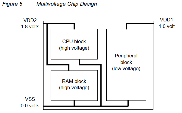
在一个芯片上提供两个或多个电源电压会带来一些复杂性和成本。需要额外的电源输入管脚提供芯片电压,而电源网络必须将每个电压电源分别分配到相应的块。
此外,当两个不同电压域的信号有通信时,需要加level-shifter cell来转换电平:

1.1 Power switching (gating)
当电路中某一部分不活动时,彻底关断其与电源的链接。
能同时降低动态和静态功耗,但有代价:
-
power controller
-
power-switching network
-
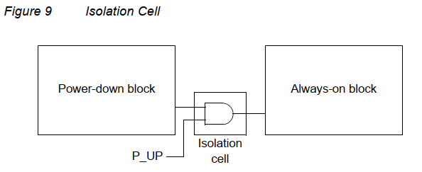
isolation cells
连在被关断的block后,提供一个常值输出防止关断后出现X态。例如下图,block关断后P_UP置为0,输出常值0
-
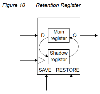
retention registers
-
通常被加载普通寄存器上作为影子寄存器,当power down时将之前的数据重新放到主寄存器内,通常用高VT的管子减少漏电
-
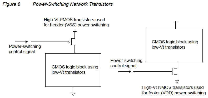
通常采用高阈值的管子做开关管来降低泄露功耗。
Dynamic Voltage and Frequency Scaling
动态电压调整需要一个多级电源和一个逻辑块来确定给定任务的最佳电压水平。由于必须分析和调节电压水平和工作频率的范围和组合,设备的设计、实现、验证和测试可能特别具有挑战性。
2. 标准UPF
由一组用于指定多电压系统的命令组成。使用UPF命令,可以为芯片设计指定supply network, power switches, isolation, retention 和其他方面。
1. UPF中的通配符
- ?匹配任意单个字符,除了层次划分符号'/'
- * 匹配0个或多个字符,除了'/'
2. 电源意图概念
-
power domain : 设计中的一组元素,它们共享一组公共的电源。默认情况下,电源域中的所有逻辑元素使用相同的主电源和主地。
- 每个domain 都有一个scope和一个extent
- scope是这个电压域被定义的逻辑层次,而extent则是属于这个电压域的逻辑元素集合。
-
supply nets 和supply ports: 每个scope都有一组supply nets 和 ports 在特定的层次结构上。
-
supply net 是在给定的电源区域内承载电源电压或接地的导体,跨越多个电压域的net被定义为“reused".
-
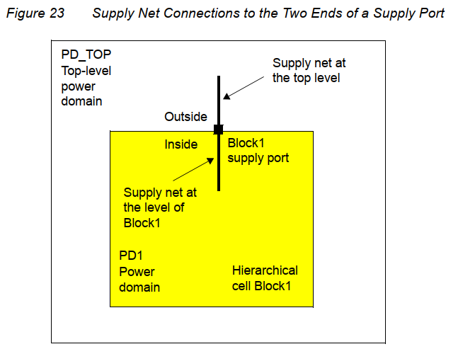
supply port 是设计层次结构的两个相邻层次之间、层次结构的父块和子块之间的电源连接点。
-
supply net 通过 supply port从设计层次结构的一个层次跨越到下一个层次
-
-
supply set: 是一个supply nets的抽象集合,一般就是一根vdd一根gnd的net。
- 是domain-independent的,在supply set中的power和ground可以被任意在该scope中定义的power domain使用。
-
supply set handle: 给一个power domain定义的抽象supply set。
-
默认情况下,每个电源domain有supply set handle for domain’s primary supply set, a default isolation
supply set, and a default retention supply set. -
supply set handle允许您在为电源域创建任何电源集、电源网络和电源端口之前综合设计。
-
-
power switch: 是一个装置,打开和关闭电源的供应网络。一个开关有一个输入供应网,一个输出供应网,以及至少一个用于控制开关的输入信号,可以通过多个信号控制,也可以输出多个信号。
-
power state table: 列出本设计中所有电源域的电压值和电源开关状态的允许组合。
-
level shifter: 电平移位器将信号从第一个域的电压摆幅转换为第二个域的电压摆幅。
-
isolation cell: 在电压域关闭期间生成一个已知的逻辑值。
-
retention registers:在具有电源开关的电源域中,在关机期间必须保留数据的任何寄存器都必须实现为保留寄存器。保留寄存器有一个单独的、始终在线的供应网络,有时称为备份供电,它在域的主供电关闭时保持保留寄存器中的数据稳定。
3. Example
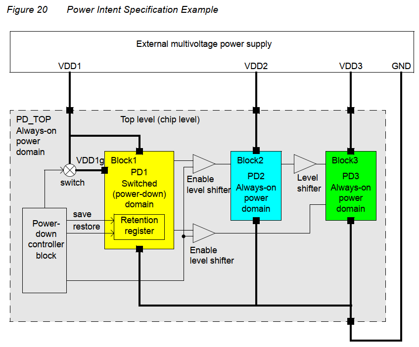
下面这个芯片工作在三个电源下,Top level 包含了 top-level的power domain: PD_TOP。
- PD_TOP包含了四个supply ports: VDD1, VDD2, VDD3, and GND.
- 除了PD_TOP,还有三个power domain: PD1, PD2, and PD3 . 分别定义在三个内层的blocks中。每个block都有若干supply ports(黑色方块),连线就是supply nets。
- 这个例子中,PD_TOP,PD2,和PD3是常开的,工作在VDD1,VDD2和VDD3下。PD1有两个supplies,一个可开关的supply: VDD1g以及一个常开的VDD1。当VDD1g关断时,其中常开的VDD1用来维持block1中的retention register。
- top-level中有一个power-down controller来控制VDD1g的开关。同时也生成retenrion register的save和restore信号。
- PD1到PD2和3之间都有isolation cell.
访问电压域,电压端口,电源网络,
有两种方法,一种是申明绝对层次结构,一种是让工具进去该层后访问。
第一种:
create_supply_net VDD1 -domain Block1/PD1
create_supply_port PRT1 -domain Block1/PD1
connect_supply_net Block1/VDD1 -ports {Block1/PRT1}
第二种:
set_scope Block1
create_supply_net VDD1 -domain PD1
create_supply_port PRT1 -domain PD1
connect_supply_net VDD1 -ports {PRT1}
set_scope ...
如果Block2和3公用相同的电源特性,他们可以连接到同一个domain,该domain可以直接在顶层中定义为PD2,所以他们可以直接链接到top level的supply port上,而不用在PD2中定义port,此时block2和3使用了顶层的supply net:
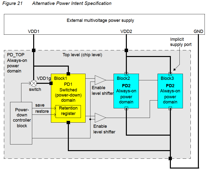
电源网VDD2是在顶层PD_TOP中定义的,但在PD2中也使用了VDD2,所以在域PD2中可以重用VDD2。一个reused的supply net 可以跨越不同的domains,并且具有相同的名称。
定义电压域
create_power_domain PD_TOP
create_power_domain PD1 -elements {Block1} -scope Block1
create_power_domain PD2 -elements {Block2} -scope Block2
create_power_domain PD3 -elements {Block3} -scope Block3
对于第二种情况,可以这么写:
create_power_domain PD_TOP
create_power_domain PD1 -elements {Block1} -scope Block1
create_power_domain PD2 -elements {Block2 Block3}
或者:
create_power_domain PD_TOP
set_scope Block1
create_power_domain PD1
set_scope ...
create_power_domain PD2 -elements {Block2 Block3}
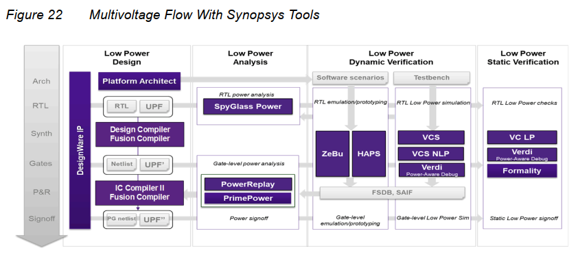
3. Synopsys 多电压域流程
Basic Power Network Commands
create_power_domain
create_power_domain domain_name
[-elements list]
[-supply {supply_set_handle supply_set_name}]
[-include_scope]
[-scope instance_name]
[-update]
create_supply_port
create_supply_port port_name
[-domain domain_name]
[-direction in | out]
creat_supply_net
create_supply_net net_name
[-domain domain_name]
[-reuse]
[-resolve unresolved | parallel | one_hot | parallel_one_hot |
user_defined_resolution_function]
connect_supply_net
connect_supply_net supply_net_name
-ports list
[-vct vct_name]
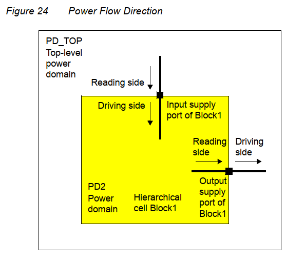
每个supply port都有内外两个port,上层次的net只能链接外端口。一个port一次只有一个端口能被连接。对于输入port,reading side是外部net,driving side是内部net.对于输出port则相反。不能给一个supply net连接多个driver, 或者说reuse一个net给多个drivers。(这里我的理解是一根net线只能连接一个driver port,如果从一个port需要drive多个port,需要指定不同的net)
create_supply_port VDD1P -domain Block1/PD1
create_supply_net VDD1 -domain Block1/PD1
connect_supply_net Block1/VDD1 -ports Block1/VDD1P
connect_supply_net VDD1 -ports Block1/VDD1P
set_domain_supply_net
set_domain_supply_net domain_name
-primary_power_net supply_net_name
-primary_ground_net supply_net_name

example:

set_domain_supply_net Block1/PD1 \
-primary_power_net Block1/VDD1 \
-primary_ground_net Block1/GND
该命令用来申明电压域的主电源网络以及主地网络。每个电压域都需要定义这些主网络。
create_power_switch (power gating)
create_power_switch switch_name
-domain domain_name
-output_supply_port {port_name supply_net_name}
{-input_supply_port {port_name supply_net_name}}*
{-control_port {port_name net_name}}*
{-on_state {state_name input_supply_port {boolean_function}}}*
[-ack_port {port_name net_name [{boolean_function}]}]*
[-ack_delay {port_name delay}]*
[-off_state {state_name {boolean_function}}]*
[-on_partial_state {state_name {boolean_function}}]*
[-error_state {state_name {boolean_function}}]*
map_power_switch
map_power_switch switch_name
-domain domain_name
-lib_cells list
create_supply_set
create_supply_set supply_set_name
[-function {function net_name}]
[-update]
包含两种functions:
• Power
• Ground
associate_supply_set
associate_supply_set supply_set_name
-handle supply_set_name
当两个set被associate后,他们将被连到相同的supply net或相同的PG pins对上。
set_equivalent
set_equivalent -nets supply_nets | -sets supply_sets
[-function_only]
指定一系列supply nets或一系列supply sets是相等的。表示他们具有相同的状态和电压,无论他们是否是电气相连的。例如:
prompt> set_equivalent -nets {VDDa VDDb VDDc} # equivalent supply nets
prompt> set_equivalent -sets {SS1a SS1b} # equivalent supply sets
funtion_only 选项指定这些相同的set是电气等价的还是相互独立并行的等价,并非一定是短路的。
Level Shifter Commands
set_level_shifter
set_level_shifter strategy_name
-domain domain_name
[-elements port_pin_list]
[-exclude_elements exclude_list]
[-applies_to inputs | outputs | both]
[-applies_to_boundary upper | lower | both]
[-threshold float]
[-rule low_to_high | high_to_low | both]
[-location self | parent | fanout | automatic]
[-no_shift]
[-force_shift]
[-name_prefix prefix_string]
[-name_suffix suffix_string]
[-update]
[-source source_supply]
[-sink sink_supply]
set_level_shifter –domain domain_name –elements ... [–applies_to ...]
set_level_shifter –domain domain_name –applies_to [inputs | outputs]
set_level_shifter –domain domain_name [–applies_to both]
map_level_shifter_cell
map_level_shifter_cell strategy_name
-domain power_domain_name
-lib_cells list
use_interface_cell
use_interface_cell
interface_implementation_name
-domain domain_name
-lib_cells lib_cell_list
-strategy list_of_one_level_shifter_and_or_one_isolation
[-port_map port_net_list]
[-force_function]
Isolation Commands
set_isolation
set_isolation isolation_strategy_name
-domain power_domain
[-elements objects]
[-exclude_elements exclude_list]
[-applies_to inputs | outputs | both]
[-applies_to_boundary upper | lower | both]
[-clamp_value 0 | 1 | latch]
[-isolation_power_net isolation_power_net]
[-isolation_ground_net isolation_ground_net]
[-isolation_supply isolation_supply_set]
[-source source_supply_set_name]
[-sink sink_supply_set_name]
[-diff_supply_only true | false]
[-no_isolation]
[-force_isolation]
[-name_prefix prefix_string]
[-name_suffix suffix_string]
[-update]
set_isolation_control
set_isolation_control isolation_strategy_name
-domain power_domain
-isolation_signal isolation_signal
[-isolation_sense high | low]
[-location self | parent | fanout]
map_isolation_cell
use_interface_cell
Retention Commands
set_retention
set_retention_control
set_retention_elements
map_retention_cell
Power Model Commands
Power State Table Commands
Logic Editing Commands
Utility Commands
load_upf
load_upf upf_file_name
[-supplemental supf_file_name]
[-scope string]
[-noecho]
[-simulation_only]
[-strict_check string]
save_upf
save_upf upf_file_name
[-supplemental supf_file_name]
[-include_supply_exceptions]
[-full_upf]
Query Commands
Simulation/Verification Extension Commands
Supply Sets
Golden UPF Flow
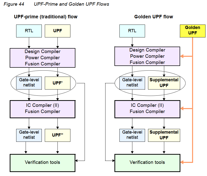
- 在整个流程中,黄金UPF文件保持不变,它保留了在UPF文件中使用的表单、结构、注释行和通配符命名。
- 可以使用特定于工具的条件语句在不同的工具中执行不同的任务。这些语句在传统的UPF-prime流中丢失了。
- power意图的更改很容易在补充的UPF文件中进行跟踪
- 您可以选择使用Verilog netlist来存储所有PG连接信息,这使得在UPF文件中不必使用connect_supply_net命令。这可以显著地简化和减少UPF文件的总体大小。
4. UPF Script Examples
Simple Multivoltage Design

Bottom-Up Power Intent Specification
从内到外的方式,先写CPU.upf:
create_power_domain PD
create_supply_net VN -domain PD
create_supply_net GN -domain PD
set_domain_supply_net PD -primary_power_net VN -primary_ground_net GN
create_supply_port VN
create_supply_port GN
connect_supply_net VN -ports {VN}
connect_supply_net GN -ports {GN}
之后写顶层的upf:
load_upf CPU.upf -scope CPU_1
load_upf CPU.upf -scope CPU_2
# still at scope SODIUM
create_supply_port VDD1
create_supply_port VDD2
create_supply_port VSS
create_power_domain PD
create_supply_net VN1 -domain PD
connect_supply_net VN1 -ports {VDD1 CPU_1/VN}
create_supply_net VN2 -domain PD
connect_supply_net VN2 -ports {VDD2 CPU_2/VN}
create_supply_net GN -domain PD
connect_supply_net GN -ports {VSS CPU_1/GN CPU_2/GN}
set_domain_supply_net PD -primary_power_net VN1 -primary_ground_net GN
# PD, CPU_1/PD and CPU_2/PD are different power domains.
使用save_upf命令后工具会自动将顶层导入的其他upf整合到一起。
Top-Down Power Intent Specification
create_power_domain PD_CPU_1 -elements {CPU_1}
create_power_domain PD_CPU_2 -elements {CPU_2}
create_power_domain PD_SODIUM
create_supply_port VDD1
create_supply_port VDD2
create_supply_port VSS
create_supply_net VN1 -domain PD_CPU_1
create_supply_net VN1 -domain PD_SODIUM -reuse
connect_supply_net VN1 -ports {VDD1}
create_supply_net VN2 -domain PD_CPU_2
create_supply_net VN2 -domain PD_SODIUM -reuse
connect_supply_net VN2 -ports {VDD2}
create_supply_net GN -domain PD_CPU_1
create_supply_net GN -domain PD_CPU_2 -reuse
create_supply_net GN -domain PD_SODIUM -reuse
connect_supply_net GN -ports {VSS}
set_domain_supply_net PD_CPU_1 \
-primary_power_net VN1 -primary_ground_net GN
set_domain_supply_net PD_CPU_2 \
-primary_power_net VN2 -primary_ground_net GN
set_domain_supply_net PD_SODIUM \
-primary_power_net VN1 -primary_ground_net GN
Hierarchy and the get_supply_nets Command
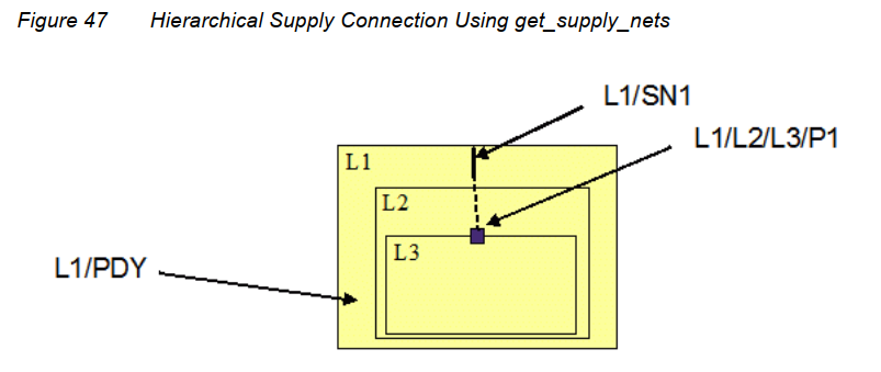
create_power_domain PDY -scope L1 -elements {L1}
create_supply_net SN1 -domain L1/PDY
create_supply_port L1/L2/L3/P1
set n [get_supply_nets SN1 -domain L1/PDY -scope L1/L2]
connect_supply_net $n -ports {L1/L2/L3/P1}
# an alternative to connect_supply_net L1/SN1 -ports {L1/L2/L3/P1}
get_supply_nets 可以在指定范围的指定域中查找与supply net关联的逻辑网名
上面例子给出了跨层次连接net和port的示例。
特定工具使用建议
VCS NLP Low Power Simulation Flow
Debugging Low-Power Designs Using Verdi
The following is the syntax to compile a low power design:
% vcs -sverilog design_file -upf upf_file -power_top design_top -kdb \ -debug_access+all compile_options
The following is the syntax to invoke the Verdi GUI:
% simv -verdi
Logic Synthesis Using Design Compiler
-
DC可以基于UPF命令和UPF指定的电源状态自动插入level shifters,isolation cells,rentention registers。
-
DC的输入文件包括RTL和用户编写的UPF,综合之后会生成一个新的UPF,新的UPF包含了一些综合过程中与电源管理单元相关的连接,如level shifters,isolation cells,rentention registers。
To synthesize a design with UPF power intent, the top-down flow is the most straightforward. These are the general steps in the flow:
- Read the RTL file.
- Use the load_upf command to read the UPF file.
- Specify the timing and power constraints.
- Compile the design using the compile_ultra command.
- Insert the scan chains using the insert_dft command.
- Use the save_upf command to save the updated constraints into a new UPF file, which can be used as input to downstream tools.
- Write the synthesis netlist into a file, which can be used as input to downstream tools.
电压域层次范例:
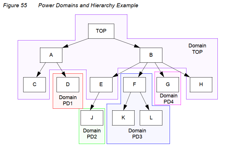
create_power_domain TOP
create_power_domain PD1 -elements {A/D}
create_power_domain PD2 -elements {B/E/J}
create_power_domain PD3 -elements {B/F}
create_power_domain PD4 -elements {B/G}
Specifying Operating Voltages
可以使用set_voltage命令在设计中指定供电网络的工作电压。
例如,以下命令指定目标库、工作条件和为设计提供净电压:
## Target Libraries
set target_library "HVT.db LVT.db SVT.db"
## Design operating condition name
set_operating_conditions WC09
## Set voltages on PN1 and PN2 supply nets
set_voltage 1.1 -object_list PN1
set_voltage 0.7 -object_list PN2
电源网络上设置的电压必须与UPF中定义的允许电压一致。
set_voltage命令允许为供电网络指定最小和最大工作条件电压。如果只指定一个电压,它适用于最大工作条件。要指定最大和最小操作条件下的电压,请使用-min选项,如下面的示例所示:
set_voltage 0.86 -min 1.06 -object_list VDD对于PST Commands来说, 一般我们在电源描述中分为两步.
Stage:1 指定nets/sets的状态.
Stage:2 创建PST表并且添加状态.
对于Stage1来说,有如下几个命令可以对nets/sets指定状态:
add_port_state -state
add_supply_state -state
add_power_state (Only with 1 function) -supply
add_power_state -supply
其中需要指出的是,add_power_state的语法是指定Set中的power&ground线的状态,如果一个state对应的是power&ground 那么我们认为这是官方2.0用法, 如果一个state对应的是power or ground (Only with 1 function),那么这是一种约定俗成的非官方1.5用法,在IEEE UPF 3.1文档中并没有进行描述但实际使用中存在的用法.
对于Stage2来说 有以下两个命令进行创表添加状态操作:
create_pst -supplies
add_power_state -group/-domain
其中add_power_state -group可以等同于create_pst操作,创建一个PST表, -domian则是指定已存在的domain的电源状态组合
Mixed PST Commands:
对于刚才提到的Stage1 与 Stage2中,都有不同的命令可以完成同样的电源意图描述,但是这些命令并不能随便组合。按照我自己的理解,被允许的组合方式符合下述一条规律:
Stage 1: 在nets上指定状态的命令 + Stage 2: create_pst
Stage 1: 在Sets上指定状态的命令 + Stage 2: add_power_state
所以被允许的组合为:
add_port_state / add_supply_state / add_power_state (UnOfficial)
+
create_pst
add_power_state
+
add_power_state
其中需要指出的是,add_power_state (Only with 1 function)是个非常特殊的用法,虽然按照语法上来说它是在Sets上指定状态,但是在实际操作中我们仍然视它是在Nets上指定状态,可以理解为它使用的是2.0的语法但是实际做的1.0的事。

 浙公网安备 33010602011771号
Power State Table Commands:
add_port_state port_name
{-state {name <nom | off>}}*
  [UPF Version 1.0]
add_supply_state object_name {-state {name <{[net_state] nom_voltage} | off>}}* [UPF Version 2.0]add_power_state [-supply | -domain | -group | -model | -instance] object_name [-update] [-state {state_name [-logic_expr {boolean_expression}] [-supply_expr {boolean_expression}] [-power_expr {power_expression}] [-simstate simstate] [-legal | -illegal] }]* [-complete] [UPF Version 2.0]create_pst table_name -supplies supply_list [UPF Version 1.0]