day31:Java和STM32的串口通信
Java向串口发送数据,STM32读取串口的数据,由此来控制LED灯的亮灭,蜂鸣器的启闭。

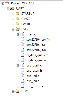
STM32代码:
工程结构:
bsp_usart.h
#ifndef __USART_H
#define	__USART_H


#include "stm32f10x.h"
#include <stdio.h>

/**
  * 串口宏定义,不同的串口挂载的总线和IO不一样,移植时需要修改这几个宏
	* 1-修改总线时钟的宏,uart1挂载到apb2总线,其他uart挂载到apb1总线
	* 2-修改GPIO的宏
  */

// 串口1-USART1
#define  DEBUG_USARTx                   USART1
#define  DEBUG_USART_CLK                RCC_APB2Periph_USART1
#define  DEBUG_USART_APBxClkCmd         RCC_APB2PeriphClockCmd
#define  DEBUG_USART_BAUDRATE           115200

// USART GPIO 引脚宏定义
#define  DEBUG_USART_GPIO_CLK           (RCC_APB2Periph_GPIOA)
#define  DEBUG_USART_GPIO_APBxClkCmd    RCC_APB2PeriphClockCmd

#define  DEBUG_USART_TX_GPIO_PORT       GPIOA
#define  DEBUG_USART_TX_GPIO_PIN        GPIO_Pin_9
#define  DEBUG_USART_RX_GPIO_PORT       GPIOA
#define  DEBUG_USART_RX_GPIO_PIN        GPIO_Pin_10

#define  DEBUG_USART_IRQ                USART1_IRQn
#define  DEBUG_USART_IRQHandler         USART1_IRQHandler


// 串口2-USART2
//#define  DEBUG_USARTx                   USART2
//#define  DEBUG_USART_CLK                RCC_APB1Periph_USART2
//#define  DEBUG_USART_APBxClkCmd         RCC_APB1PeriphClockCmd
//#define  DEBUG_USART_BAUDRATE           115200

//// USART GPIO 引脚宏定义
//#define  DEBUG_USART_GPIO_CLK           (RCC_APB2Periph_GPIOA)
//#define  DEBUG_USART_GPIO_APBxClkCmd    RCC_APB2PeriphClockCmd
//
//#define  DEBUG_USART_TX_GPIO_PORT       GPIOA
//#define  DEBUG_USART_TX_GPIO_PIN        GPIO_Pin_2
//#define  DEBUG_USART_RX_GPIO_PORT       GPIOA
//#define  DEBUG_USART_RX_GPIO_PIN        GPIO_Pin_3

//#define  DEBUG_USART_IRQ                USART2_IRQn
//#define  DEBUG_USART_IRQHandler         USART2_IRQHandler

// 串口3-USART3
//#define  DEBUG_USARTx                   USART3
//#define  DEBUG_USART_CLK                RCC_APB1Periph_USART3
//#define  DEBUG_USART_APBxClkCmd         RCC_APB1PeriphClockCmd
//#define  DEBUG_USART_BAUDRATE           115200

//// USART GPIO 引脚宏定义
//#define  DEBUG_USART_GPIO_CLK           (RCC_APB2Periph_GPIOB)
//#define  DEBUG_USART_GPIO_APBxClkCmd    RCC_APB2PeriphClockCmd
//
//#define  DEBUG_USART_TX_GPIO_PORT       GPIOB
//#define  DEBUG_USART_TX_GPIO_PIN        GPIO_Pin_10
//#define  DEBUG_USART_RX_GPIO_PORT       GPIOB
//#define  DEBUG_USART_RX_GPIO_PIN        GPIO_Pin_11

//#define  DEBUG_USART_IRQ                USART3_IRQn
//#define  DEBUG_USART_IRQHandler         USART3_IRQHandler

// 串口4-UART4
//#define  DEBUG_USARTx                   UART4
//#define  DEBUG_USART_CLK                RCC_APB1Periph_UART4
//#define  DEBUG_USART_APBxClkCmd         RCC_APB1PeriphClockCmd
//#define  DEBUG_USART_BAUDRATE           115200

//// USART GPIO 引脚宏定义
//#define  DEBUG_USART_GPIO_CLK           (RCC_APB2Periph_GPIOC)
//#define  DEBUG_USART_GPIO_APBxClkCmd    RCC_APB2PeriphClockCmd
//
//#define  DEBUG_USART_TX_GPIO_PORT       GPIOC
//#define  DEBUG_USART_TX_GPIO_PIN        GPIO_Pin_10
//#define  DEBUG_USART_RX_GPIO_PORT       GPIOC
//#define  DEBUG_USART_RX_GPIO_PIN        GPIO_Pin_11

//#define  DEBUG_USART_IRQ                UART4_IRQn
//#define  DEBUG_USART_IRQHandler         UART4_IRQHandler


// 串口5-UART5
//#define  DEBUG_USARTx                   UART5
//#define  DEBUG_USART_CLK                RCC_APB1Periph_UART5
//#define  DEBUG_USART_APBxClkCmd         RCC_APB1PeriphClockCmd
//#define  DEBUG_USART_BAUDRATE           115200

//// USART GPIO 引脚宏定义
//#define  DEBUG_USART_GPIO_CLK           (RCC_APB2Periph_GPIOC|RCC_APB2Periph_GPIOD)
//#define  DEBUG_USART_GPIO_APBxClkCmd    RCC_APB2PeriphClockCmd
//
//#define  DEBUG_USART_TX_GPIO_PORT       GPIOC
//#define  DEBUG_USART_TX_GPIO_PIN        GPIO_Pin_12
//#define  DEBUG_USART_RX_GPIO_PORT       GPIOD
//#define  DEBUG_USART_RX_GPIO_PIN        GPIO_Pin_2

//#define  DEBUG_USART_IRQ                UART5_IRQn
//#define  DEBUG_USART_IRQHandler         UART5_IRQHandler


void USART_Config(void);
void Usart_SendByte( USART_TypeDef * pUSARTx, uint8_t ch);
void Usart_SendString( USART_TypeDef * pUSARTx, char *str);
void Usart_SendHalfWord( USART_TypeDef * pUSARTx, uint16_t ch);

#endif /* __USART_H */
bsp_usart.c
/**
  ******************************************************************************
  * @file    bsp_usart.c
  * @author  fire
  * @version V1.0
  * @date    2013-xx-xx
  * @brief   重定向c库printf函数到usart端口
  ******************************************************************************
  * @attention
  *
  * 实验平台:秉火STM32 F103-MINI 开发板
  * 论坛    :http://www.firebbs.cn
  * 淘宝    :https://fire-stm32.taobao.com
  *
  ******************************************************************************
  */

#include "bsp_usart.h"

 /**
  * @brief  配置嵌套向量中断控制器NVIC
  * @param  无
  * @retval 无
  */
static void NVIC_Configuration(void)
{
  NVIC_InitTypeDef NVIC_InitStructure;

  /* 嵌套向量中断控制器组选择 */
  NVIC_PriorityGroupConfig(NVIC_PriorityGroup_2);

  /* 配置USART为中断源 */
  NVIC_InitStructure.NVIC_IRQChannel = DEBUG_USART_IRQ;
  /* 抢断优先级*/
  NVIC_InitStructure.NVIC_IRQChannelPreemptionPriority = 1;
  /* 子优先级 */
  NVIC_InitStructure.NVIC_IRQChannelSubPriority = 1;
  /* 使能中断 */
  NVIC_InitStructure.NVIC_IRQChannelCmd = ENABLE;
  /* 初始化配置NVIC */
  NVIC_Init(&NVIC_InitStructure);
}

 /**
  * @brief  USART GPIO 配置,工作参数配置
  * @param  无
  * @retval 无
  */
void USART_Config(void)
{
	GPIO_InitTypeDef GPIO_InitStructure;
	USART_InitTypeDef USART_InitStructure;

	// 打开串口GPIO的时钟
	DEBUG_USART_GPIO_APBxClkCmd(DEBUG_USART_GPIO_CLK, ENABLE);

	// 打开串口外设的时钟
	DEBUG_USART_APBxClkCmd(DEBUG_USART_CLK, ENABLE);

	// 将USART Tx的GPIO配置为推挽复用模式
	GPIO_InitStructure.GPIO_Pin = DEBUG_USART_TX_GPIO_PIN;
	GPIO_InitStructure.GPIO_Mode = GPIO_Mode_AF_PP;
	GPIO_InitStructure.GPIO_Speed = GPIO_Speed_50MHz;
	GPIO_Init(DEBUG_USART_TX_GPIO_PORT, &GPIO_InitStructure);

  // 将USART Rx的GPIO配置为浮空输入模式
	GPIO_InitStructure.GPIO_Pin = DEBUG_USART_RX_GPIO_PIN;
	GPIO_InitStructure.GPIO_Mode = GPIO_Mode_IN_FLOATING;
	GPIO_Init(DEBUG_USART_RX_GPIO_PORT, &GPIO_InitStructure);

	// 配置串口的工作参数
	// 配置波特率
	USART_InitStructure.USART_BaudRate = DEBUG_USART_BAUDRATE;
	// 配置 针数据字长
	USART_InitStructure.USART_WordLength = USART_WordLength_8b;
	// 配置停止位
	USART_InitStructure.USART_StopBits = USART_StopBits_1;
	// 配置校验位
	USART_InitStructure.USART_Parity = USART_Parity_No ;
	// 配置硬件流控制
	USART_InitStructure.USART_HardwareFlowControl =
	USART_HardwareFlowControl_None;
	// 配置工作模式,收发一起
	USART_InitStructure.USART_Mode = USART_Mode_Rx | USART_Mode_Tx;
	// 完成串口的初始化配置
	USART_Init(DEBUG_USARTx, &USART_InitStructure);

	// 串口中断优先级配置
	NVIC_Configuration();

	// 使能串口接收中断
	USART_ITConfig(DEBUG_USARTx, USART_IT_RXNE, ENABLE);
	USART_ITConfig ( DEBUG_USARTx, USART_IT_IDLE, ENABLE ); //使能串口总线空闲中断


	// 使能串口
	USART_Cmd(DEBUG_USARTx, ENABLE);
}

/*****************  发送一个字节 **********************/
void Usart_SendByte( USART_TypeDef * pUSARTx, uint8_t ch)
{
	/* 发送一个字节数据到USART */
	USART_SendData(pUSARTx,ch);

	/* 等待发送数据寄存器为空 */
	while (USART_GetFlagStatus(pUSARTx, USART_FLAG_TXE) == RESET);
}

/****************** 发送8位的数组 ************************/
void Usart_SendArray( USART_TypeDef * pUSARTx, uint8_t *array, uint16_t num)
{
  uint8_t i;

	for(i=0; i<num; i++)
  {
	    /* 发送一个字节数据到USART */
	    Usart_SendByte(pUSARTx,array[i]);

  }
	/* 等待发送完成 */
	while(USART_GetFlagStatus(pUSARTx,USART_FLAG_TC)==RESET);
}

/*****************  发送字符串 **********************/
void Usart_SendString( USART_TypeDef * pUSARTx, char *str)
{
	unsigned int k=0;
  do
  {
      Usart_SendByte( pUSARTx, *(str + k) );
      k++;
  } while(*(str + k)!='\0');

  /* 等待发送完成 */
  while(USART_GetFlagStatus(pUSARTx,USART_FLAG_TC)==RESET)
  {}
}

/*****************  发送一个16位数 **********************/
void Usart_SendHalfWord( USART_TypeDef * pUSARTx, uint16_t ch)
{
	uint8_t temp_h, temp_l;

	/* 取出高八位 */
	temp_h = (ch&0XFF00)>>8;
	/* 取出低八位 */
	temp_l = ch&0XFF;

	/* 发送高八位 */
	USART_SendData(pUSARTx,temp_h);
	while (USART_GetFlagStatus(pUSARTx, USART_FLAG_TXE) == RESET);

	/* 发送低八位 */
	USART_SendData(pUSARTx,temp_l);
	while (USART_GetFlagStatus(pUSARTx, USART_FLAG_TXE) == RESET);
}

///重定向c库函数printf到串口,重定向后可使用printf函数
int fputc(int ch, FILE *f)
{
		/* 发送一个字节数据到串口 */
		USART_SendData(DEBUG_USARTx, (uint8_t) ch);

		/* 等待发送完毕 */
		while (USART_GetFlagStatus(DEBUG_USARTx, USART_FLAG_TXE) == RESET);

		return (ch);
}

///重定向c库函数scanf到串口,重写向后可使用scanf、getchar等函数
int fgetc(FILE *f)
{
		/* 等待串口输入数据 */
		while (USART_GetFlagStatus(DEBUG_USARTx, USART_FLAG_RXNE) == RESET);

		return (int)USART_ReceiveData(DEBUG_USARTx);
}
rx_data_queue.h
#ifndef __ESP_DATA_QUEUE_H_
#define __ESP_DATA_QUEUE_H_

#include "stm32f10x.h"

#include <string.h>
#include <stdio.h>

//缓冲队列的个数需要为2的幂
#define QUEUE_NODE_NUM        (2)			//缓冲队列的大小(有多少个缓冲区)
#define QUEUE_NODE_DATA_LEN   (2*1024 )		//单个接收缓冲区大小

// 队列的主体数据类型接口
#define QUEUE_DATA_TYPE  				ESP_USART_FRAME
// 队列的调试输出接口
#define DATA_QUEUE_LOG  				QUEUE_DEBUG
#define DATA_QUEUE_LOG_ARRAY 	QUEUE_DEBUG_ARRAY


// 数据主体
typedef struct
{
	char  *head; 	// 缓冲区头指针
	uint16_t len; 	// 接收到的数据长度

}ESP_USART_FRAME;


// 队列结构
typedef struct {
	int         size;  		/* 缓冲区大小 */
	int         read; 		/* 读指针 */
	int         write;   	/* 写指针 */
	int read_using;			/* 正在读取的缓冲区指针 */
	int write_using;		/* 正在写入的缓冲区指针 */
	QUEUE_DATA_TYPE    *elems[QUEUE_NODE_NUM];  /* 缓冲区地址 */
} QueueBuffer;

extern QueueBuffer rx_queue;

/* 信息输出 */
#define QUEUE_DEBUG_ON         1
#define QUEUE_DEBUG_ARRAY_ON		1

#define QUEUE_INFO(fmt,arg...)           printf("<<-QUEUE-INFO->> "fmt"\n",##arg)
#define QUEUE_ERROR(fmt,arg...)          printf("<<-QUEUE-ERROR->> "fmt"\n",##arg)
#define QUEUE_DEBUG(fmt,arg...)          do{\
                                          if(QUEUE_DEBUG_ON)\
                                          printf("<<-QUEUE-DEBUG->> [%d]"fmt"\n",__LINE__, ##arg);\
                                          }while(0)

#define QUEUE_DEBUG_ARRAY(array, num)    do{\
	 int32_t i;\
	 uint8_t* a = array;\
	 if(QUEUE_DEBUG_ARRAY_ON)\
	 {\
			printf("\n<<-QUEUE-DEBUG-ARRAY->>\n");\
			for (i = 0; i < (num); i++)\
			{\
					printf("%02x   ", (a)[i]);\
					if ((i + 1 ) %10 == 0)\
					{\
							printf("\n");\
					}\
			}\
			printf("\n");\
	}\
 }while(0)

//输出队列的状态信息
#define cbPrint(cb)		    DATA_QUEUE_LOG("size=0x%x, read=%d, write=%d\n", cb.size, cb.read, cb.write);\
	  DATA_QUEUE_LOG("size=0x%x, read_using=%d, write_using=%d\n", cb.size, cb.read_using, cb.write_using);


QUEUE_DATA_TYPE* cbWrite(QueueBuffer *cb);
QUEUE_DATA_TYPE* cbRead(QueueBuffer *cb);
void cbReadFinish(QueueBuffer *cb);
void cbWriteFinish(QueueBuffer *cb);
//void cbPrint(QueueBuffer *cb);
QUEUE_DATA_TYPE* cbWriteUsing(QueueBuffer *cb) ;
int cbIsFull(QueueBuffer *cb) ;
int cbIsEmpty(QueueBuffer *cb) ;

void rx_queue_init(void);
void pull_data_from_queue(void);
void push_data_to_queue(char *src_dat,uint16_t src_len);

#endif
rx_data_queue.c
/**
  ******************************************************************************
  * @file    rx_data_queue.c
  * @author  fire
  * @version V1.0
  * @date    2015-01-xx
  * @brief   环形缓冲区,适用于接收外部数据时用作缓冲
  ******************************************************************************
  * @attention
  *
  * 实验平台:秉火 IOT STM32 开发板
  * 论坛    :http://www.firebbs.cn
  * 淘宝    :https://fire-stm32.taobao.com
  *
  ******************************************************************************
  */

#include "./uart/rx_data_queue.h"


//实例化节点数据类型
QUEUE_DATA_TYPE  node_data[QUEUE_NODE_NUM];
//实例化队列类型
QueueBuffer rx_queue;

//队列缓冲区的内存池
__align(4) char node_buff[QUEUE_NODE_NUM][QUEUE_NODE_DATA_LEN] ;


/*环形缓冲队列*/

/**
  * @brief  初始化缓冲队列
  * @param  cb:缓冲队列结构体
  * @param  size: 缓冲队列的元素个数
  * @note 	初始化时还需要给cb->elems指针赋值
  */
void cbInit(QueueBuffer *cb, int size)
{
    cb->size  = size;	/* maximum number of elements           */
    cb->read = 0; 		/* index of oldest element              */
    cb->write   = 0; 	 	/* index at which to write new element  */
//    cb->elems = (uint8_t *)calloc(cb->size, sizeof(uint8_t));  //elems 要额外初始化
}

//(此函数改成了宏,在头文件)
/**
  * @brief  输出缓冲队列当前的状态信息
  * @param  cb:缓冲队列结构体
  */
//void cbPrint(QueueBuffer *cb)
//{
//    DATA_QUEUE_LOG("size=0x%x, read=%d, write=%d\n", cb->size, cb->read, cb->write);
//	  DATA_QUEUE_LOG("size=0x%x, read_using=%d, write_using=%d\n", cb->size, cb->read_using, cb->write_using);
//}

/**
  * @brief  判断缓冲队列是(1)否(0)已满
  * @param  cb:缓冲队列结构体
  */
int cbIsFull(QueueBuffer *cb)
{
    return cb->write == (cb->read ^ cb->size); /* This inverts the most significant bit of read before comparison */
}

/**
  * @brief  判断缓冲队列是(1)否(0)全空
  * @param  cb:缓冲队列结构体
  */
int cbIsEmpty(QueueBuffer *cb)
{
    return cb->write == cb->read;
}

/**
  * @brief  对缓冲队列的指针加1
  * @param  cb:缓冲队列结构体
  * @param  p:要加1的指针
  * @return  返回加1的结果
  */
int cbIncr(QueueBuffer *cb, int p)
{
    return (p + 1)&(2*cb->size-1); /* read and write pointers incrementation is done modulo 2*size */
}

/**
  * @brief  获取可写入的缓冲区指针
  * @param  cb:缓冲队列结构体
  * @return  可进行写入的缓冲区指针
  * @note  得到指针后可进入写入操作,但写指针不会立即加1,
           写完数据时,应调用cbWriteFinish对写指针加1
  */
QUEUE_DATA_TYPE* cbWrite(QueueBuffer *cb)
{
    if (cbIsFull(cb)) /* full, overwrite moves read pointer */
    {
			return NULL;
		}
		else
		{
			//当wriet和write_using相等时,表示上一个缓冲区已写入完毕,需要对写指针加1
			if(cb->write == cb->write_using)
			{
				cb->write_using = cbIncr(cb, cb->write); //未满,则增加1
			}
		}

	return  cb->elems[cb->write_using&(cb->size-1)];
}


/**
  * @brief 数据写入完毕,更新写指针到缓冲结构体
  * @param  cb:缓冲队列结构体
  */
void cbWriteFinish(QueueBuffer *cb)
{
    cb->write = cb->write_using;
}

/**
  * @brief  获取可读取的缓冲区指针
  * @param  cb:缓冲队列结构体
  * @return  可进行读取的缓冲区指针
  * @note  得到指针后可进入读取操作,但读指针不会立即加1,
					 读取完数据时,应调用cbReadFinish对读指针加1
  */
QUEUE_DATA_TYPE* cbRead(QueueBuffer *cb)
{
		if(cbIsEmpty(cb))
			return NULL;

	//当read和read_using相等时,表示上一个缓冲区已读取完毕(即已调用cbReadFinish),
	//需要对写指针加1
	if(cb->read == cb->read_using)
		cb->read_using = cbIncr(cb, cb->read);

	return cb->elems[cb->read_using&(cb->size-1)];
}


/**
  * @brief 数据读取完毕,更新读指针到缓冲结构体
  * @param  cb:缓冲队列结构体
  */
void cbReadFinish(QueueBuffer *cb)
{
		//重置当前读完的数据节点的长度
		cb->elems[cb->read_using&(cb->size-1)]->len = 0;

    cb->read = cb->read_using;
}


//队列的指针指向的缓冲区全部销毁
void camera_queue_free(void)
{
    uint32_t i = 0;

    for(i = 0; i < QUEUE_NODE_NUM; i ++)
    {
        if(node_data[i].head != NULL)
        {
					//若是动态申请的空间才要free
//            free(node_data[i].head);
            node_data[i].head = NULL;
        }
    }

    return;
}


/**
  * @brief  缓冲队列初始化,分配内存,使用缓冲队列时,
  * @param  无
  * @retval 无
  */
void rx_queue_init(void)
{
  uint32_t i = 0;

  memset(node_data, 0, sizeof(node_data));

	/*初始化缓冲队列*/
	cbInit(&rx_queue,QUEUE_NODE_NUM);

    for(i = 0; i < QUEUE_NODE_NUM; i ++)
    {
        node_data[i].head = node_buff[i];

        /*初始化队列缓冲指针,指向实际的内存*/
        rx_queue.elems[i] = &node_data[i];

        DATA_QUEUE_LOG("node_data[i].head=0x%x,\r\nrx_queue.elems[i] =0x%x", (uint32_t)node_data[i].head,(uint32_t)rx_queue.elems[i]->head);

        memset(node_data[i].head, 0, QUEUE_NODE_DATA_LEN);
    }

	cbPrint(rx_queue);
}


/**
  * @brief  往队列中写入数据的样例
  */
void push_data_to_queue(char *src_dat,uint16_t src_len)
{
	QUEUE_DATA_TYPE *data_p;
	uint8_t i;

	for(i=0;i<src_len;i++)
	{
		/*获取写缓冲区指针,准备写入新数据*/
		data_p = cbWrite(&rx_queue);

		if (data_p != NULL)	//若缓冲队列未满,开始传输
		{
			//往缓冲区写入数据,如使用串口接收、dma写入等方式
			*(data_p->head + i) = src_dat[i];
				data_p->len++;
			printf("\r\ndata_p->len =%d",data_p->len);
		}else return;

		cbPrint(rx_queue);
	}

	/*写入缓冲区完毕*/
	cbWriteFinish(&rx_queue);

	cbPrint(rx_queue);

}


/**
  * @brief  从队列中取数据的样例
  */
void pull_data_from_queue(void)
{
	QUEUE_DATA_TYPE *rx_data;

	/*从缓冲区读取数据,进行处理,*/
	rx_data = cbRead(&rx_queue);

	if(rx_data != NULL)//缓冲队列非空
	{
		//加上字符串结束符,方便直接输出字符串
		*(rx_data->head+rx_data->len) = '\0';

		QUEUE_DEBUG("接收到的数据:%s",rx_data->head);
		QUEUE_DEBUG_ARRAY((uint8_t*)rx_data->head,rx_data->len);

		//使用完数据必须调用cbReadFinish更新读指针
		cbReadFinish(&rx_queue);
	}
}
stm32f10x_it.c中添加函数:
// 串口中断服务函数
// 把接收到的数据写入缓冲区,在main函数中轮询缓冲区输出数据
void DEBUG_USART_IRQHandler(void)
{
	uint8_t ucCh;
	QUEUE_DATA_TYPE *data_p;

	if(USART_GetITStatus(DEBUG_USARTx,USART_IT_RXNE)!=RESET)
	{
		ucCh  = USART_ReceiveData( DEBUG_USARTx );

		/*获取写缓冲区指针,准备写入新数据*/
		data_p = cbWrite(&rx_queue);

		if (data_p != NULL)	//若缓冲队列未满,开始传输
		{

			//往缓冲区写入数据,如使用串口接收、dma写入等方式
			*(data_p->head + data_p->len) = ucCh;

			if( ++data_p->len >= QUEUE_NODE_DATA_LEN)
			{
				cbWriteFinish(&rx_queue);
			}
		}else return;
	}

	if ( USART_GetITStatus( DEBUG_USARTx, USART_IT_IDLE ) == SET )  //数据帧接收完毕
	{
			/*写入缓冲区完毕*/
			cbWriteFinish(&rx_queue);
		ucCh = USART_ReceiveData( DEBUG_USARTx );     //由软件序列清除中断标志位(先读USART_SR,然后读USART_DR)

	}
}
bsp_led.h
/* 和LED功能模块相关的程序 */

#ifndef __BSP_LED_H__
#define __BSP_LED_H__

#include "stm32f10x.h"

/*宏定义*/
#define GPIO_CLK_D4         RCC_APB2Periph_GPIOC        // 时钟
#define GPIO_PORT_D4        GPIOC                       // C端口
#define GPIO_PIN_D4         GPIO_Pin_2                  // PC2引脚

#define GPIO_CLK_D5         RCC_APB2Periph_GPIOC        // 时钟
#define GPIO_PORT_D5        GPIOC                       // C端口
#define GPIO_PIN_D5         GPIO_Pin_3                  // PC2引脚

/*参数宏定义*/
/*
digitalTOGGLE(p,i)是参数宏定义,p表示LED的端口号,ODR是数据输出寄存器,
查stm32f10x的官方中文手册的第8.2章的ODR寄存器,要点亮LED,根据原理图,要输出低电平0,
C语言中,^表示异或,即a^b表示a和b不同时输出为1,相同时输出为0,比如0^1=1,1^1=0,0^0=0,
这里为什么操作ODR,p是什么?查看stm32f10x.h文件,搜索GPIO_TypeDef就会明白,
i是LED的引脚对应的位电平,经过digitalTOGGLE(p,i) {p->ODR ^= i;}之后,
第一次p为0,i一直为1,第一次异或结果输出1,第二次输出0,第三次输出1,这样间断输出010101,灯不断亮灭
*/
// LED灯的状态翻转
//#define digitalTOGGLE(p,i)    {p->ODR ^= i;}
// 输出高电平(让LED端口置1,BSRR寄存器用于位置1)
#define digitalHi(p,i)          {p->BSRR = i;}
// 输出低电平(让LED端口置0,BRR寄存器用于位清除)
#define digitalLo(p,i)          {p->BRR = i;}

// LED状态翻转
//#define LED1_TOGGLE           digitalTOGGLE(GPIO_PORT_D4,GPIO_PIN_D4)
//#define LED2_TOGGLE           digitalTOGGLE(GPIO_PORT_D5,GPIO_PIN_D5)
// D4这个LED亮
#define D4_LED_ON               digitalLo(GPIO_PORT_D4,GPIO_PIN_D4)
// D4这个LED灭
#define D4_LED_OFF              digitalHi(GPIO_PORT_D4,GPIO_PIN_D4)
// D5这个LED亮
#define D5_LED_ON               digitalLo(GPIO_PORT_D5,GPIO_PIN_D5)
// D5这个LED灭
#define D5_LED_OFF              digitalHi(GPIO_PORT_D5,GPIO_PIN_D5)


/*配置GPIO*/
void LED_GPIO_Config(void);

#endif  /*__BSP_LED_H__*/
bsp_led.c
/* 和LED功能模块相关的程序头文件 */

/*绝对路径,也可在Options for target中设置头文件*/
#include "./led/bsp_led.h"

/*GPIO初始化*/
void LED_GPIO_Config(void)
{
    /*外设结构体*/
    GPIO_InitTypeDef GPIO_InitStruct_D4, GPIO_InitStruct_D5;

    /*第一步:打开外设的时钟,看stm32f10x_rcc.c这个文件的RCC_APB2PeriphClockCmd函数介绍*/
    RCC_APB2PeriphClockCmd(GPIO_CLK_D4, ENABLE);

    /*第二步:配置外设的初始化结构体*/
    GPIO_InitStruct_D4.GPIO_Pin = GPIO_PIN_D4;          // PC2的那盏LED灯(D4)的引脚
    GPIO_InitStruct_D4.GPIO_Mode = GPIO_Mode_Out_PP;    // 推挽输出模式
    GPIO_InitStruct_D4.GPIO_Speed = GPIO_Speed_10MHz;   // 引脚速率

    GPIO_InitStruct_D5.GPIO_Pin = GPIO_PIN_D5;          // PC3的那盏LED灯(D5)的引脚
    GPIO_InitStruct_D5.GPIO_Mode = GPIO_Mode_Out_PP;    // 推挽输出模式
    GPIO_InitStruct_D5.GPIO_Speed = GPIO_Speed_10MHz;   // 引脚速率

    /*第三步:调用外设初始化函数,把配置好的结构体成员写到寄存器里面*/
    GPIO_Init(GPIO_PORT_D4, &GPIO_InitStruct_D4);
    GPIO_Init(GPIO_PORT_D5, &GPIO_InitStruct_D5);

    /* 默认情况下D4和D5是不亮的 */
    D4_LED_OFF;
    D5_LED_OFF;
}
bsp_buzzer.h
#ifndef __BSP_BUZZER_H__
#define __BSP_BUZZER_H__

#include "stm32f10x.h"

// 蜂鸣器用到的引脚(PC1)
#define GPIO_BUZZER_CLK             RCC_APB2Periph_GPIOC
#define GPIO_BUZZER_PORT            GPIOC
#define GPIO_BUZZER_PIN             GPIO_Pin_1

/*蜂鸣器GPIO端口初始化*/
void GPIO_Buzzer_Init(void);

/*蜂鸣器发声*/
void Buzzer_Lissen(void);

/*关闭蜂鸣器*/
void Buzzer_Close(void);

#endif  /*__BSP_BUZZER_H__*/
bsp_buzzer.c
#include "./buzzer/bsp_buzzer.h"

/*延迟函数*/
static void Delay(__IO uint32_t time)
{
    for(;time!=0;time--);
}

/*蜂鸣器GPIO端口初始化*/
void GPIO_Buzzer_Init(void)
{
    // 结构体
    GPIO_InitTypeDef GPIO_InitStruct;

    // 开时钟
    RCC_APB2PeriphClockCmd(GPIO_BUZZER_CLK, ENABLE);

    // 实例化
    GPIO_InitStruct.GPIO_Pin = GPIO_BUZZER_PIN;
    GPIO_InitStruct.GPIO_Mode = GPIO_Mode_Out_PP;
    GPIO_InitStruct.GPIO_Speed = GPIO_Speed_50MHz;

    // 初始化
    GPIO_Init(GPIO_BUZZER_PORT, &GPIO_InitStruct);
}

/*蜂鸣器发声*/
void Buzzer_Lissen(void)
{
    uint32_t i = 10000;
    // 产生PWM波,高低电平振荡发声
    //while(i--)
    //{
        GPIO_SetBits(GPIO_BUZZER_PORT, GPIO_BUZZER_PIN);
        Delay(100*i);
        GPIO_ResetBits(GPIO_BUZZER_PORT, GPIO_BUZZER_PIN);
        Delay(200*i);
    //}
}

/*关闭蜂鸣器*/
void Buzzer_Close(void)
{
	//uint32_t j = 10000;
    // 产生PWM波,高低电平振荡发声
    //while(j--)
    //{
        GPIO_ResetBits(GPIO_BUZZER_PORT, GPIO_BUZZER_PIN);
    //}
}
main.c
#include "stm32f10x.h"
#include "./uart/bsp_usart.h"
#include "./led/bsp_led.h"
#include "./buzzer/bsp_buzzer.h"

int main(void)
{
    // 接收到的数据存放到局部变量中
    uint8_t temp;

    /* LED初始化 */
    LED_GPIO_Config();
	GPIO_Buzzer_Init();

    /* USART串口通信初始化 */
    USART_Config();

	// 控制LED和蜂鸣器
    while(1)
    {
		temp = USART_ReceiveData(DEBUG_USARTx);

        switch(temp)
        {
			case '0':
                D4_LED_OFF;
                break;

            case '1':
                D4_LED_ON;
                break;

			case '2':
                Buzzer_Lissen();
                break;

			case '3':
                Buzzer_Close();
                break;
        }
    }
}
Java代码:
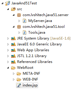
index.jsp
<%@ page language="java" import="java.util.*" pageEncoding="UTF-8"%>
<%
String path = request.getContextPath();
String basePath = request.getScheme()+"://"+request.getServerName()+":"+request.getServerPort()+path+"/";
%>

<!DOCTYPE HTML PUBLIC "-//W3C//DTD HTML 4.01 Transitional//EN">
<html>
<head>
<base href="<%=basePath%>">

<title>Web控制51单片机的各个功能模块之案例测试</title>
<meta http-equiv="pragma" content="no-cache">
<meta http-equiv="cache-control" content="no-cache">
<meta http-equiv="expires" content="0">
<meta http-equiv="keywords" content="keyword1,keyword2,keyword3">
<meta http-equiv="description" content="This is my page">

<script type="text/javascript">
	// 开LED
	function goON() {
		var parameterId = document.getElementById("parameterId");
		parameterId.value = "on";
		document.forms[0].submit();
	}

	// 关LED
	function goOFF() {
		var parameterId = document.getElementById("parameterId");
		parameterId.value = "off";
		document.forms[0].submit();
	}

	// 开蜂鸣器
	function buzzer_goON() {
		var parameterId = document.getElementById("parameterId");
		parameterId.value = "buzzer_on";
		document.forms[0].submit();
	}

	// 关蜂鸣器
	function buzzer_goOFF() {
		var parameterId = document.getElementById("parameterId");
		parameterId.value = "buzzer_off";
		document.forms[0].submit();
	}
</script>
</head>

<body>
	<h2>========= Java和STM32串口通信实验 =========</h2>
	说明:按下“开灯”按钮打开LED灯,按下“关灯”按钮关闭LED灯
	<br><br>
	<form name="myForm" action="operator" method="post" style="margin-left: 200px;">
		<input type="hidden" name="parameter" id="parameterId"/>
		<table cellpadding="7" cellspacing="10">
			<tr>
				<td>
					<input type="hidden" name="on" value="1" readonly="readonly"/>
					<input type="button" value="开灯" onclick="goON();" style="font-size: 20px;"/>
				</td>
				<td>
					<input type="hidden" name="off" value="0" readonly="readonly"/>
					<input type="button" value="关灯" onclick="goOFF();" style="font-size: 20px;"/>
				</td>
			</tr>
			<tr>
				<td>
					<input type="hidden" name="buzzer_on" value="2" readonly="readonly"/>
					<input type="button" value="开蜂鸣器" onclick="buzzer_goON();" style="font-size: 20px;"/>
				</td>
				<td>
					<input type="hidden" name="buzzer_off" value="3" readonly="readonly"/>
					<input type="button" value="关蜂鸣器" onclick="buzzer_goOFF();" style="font-size: 20px;"/>
				</td>
			</tr>
		</table>
	</form>
</body>
</html>
web.xml
<?xml version="1.0" encoding="UTF-8"?>
<!DOCTYPE web-app PUBLIC "-//Sun Microsystems, Inc.//DTD Web Application 2.3//EN" "http://java.sun.com/dtd/web-app_2_3.dtd">
<web-app>
	<servlet>
		<servlet-name>operator</servlet-name>
		<servlet-class>com.lvshitech.java51.server.MyServer</servlet-class>
	</servlet>

	<servlet-mapping>
		<servlet-name>operator</servlet-name>
		<url-pattern>/operator</url-pattern>
	</servlet-mapping>
</web-app>
MyServer.java
package com.lvshitech.java51.server;

import java.io.IOException;

import javax.servlet.ServletException;
import javax.servlet.http.HttpServlet;
import javax.servlet.http.HttpServletRequest;
import javax.servlet.http.HttpServletResponse;

import com.lvshitech.java51.tool.Tools;

@SuppressWarnings("serial")
public class MyServer extends HttpServlet {

	@Override
	protected void doPost(HttpServletRequest req, HttpServletResponse resp)
			throws ServletException, IOException {
		// 获取参数
		String parameter = req.getParameter("parameter");
		String on = req.getParameter("on");
		String off = req.getParameter("off");
		String buzzer_on = req.getParameter("buzzer_on");
		String buzzer_off = req.getParameter("buzzer_off");

		try {
			if(null==parameter || "".equals(parameter)) {
				System.out.println("接收到的参数为空!");
			} else {
				if("on".equals(parameter)) {
					Tools.action(on);
				}
				if("off".equals(parameter)) {
					Tools.action(off);
				}
				if("buzzer_on".equals(parameter)) {
					Tools.action(buzzer_on);
				}
				if("buzzer_off".equals(parameter)){
					Tools.action(buzzer_off);
				}
			}
		} catch (Exception e) {
			e.printStackTrace();
		} finally {
			Tools.closePort();
		}

		req.getRequestDispatcher("index.jsp").forward(req, resp);
	}

	@Override
	protected void doGet(HttpServletRequest req, HttpServletResponse resp)
			throws ServletException, IOException {
		this.doPost(req, resp);
	}
}
Tools.java
package com.lvshitech.java51.tool;

import gnu.io.CommPort;
import gnu.io.CommPortIdentifier;
import gnu.io.NoSuchPortException;
import gnu.io.PortInUseException;
import gnu.io.SerialPort;
import gnu.io.UnsupportedCommOperationException;

import java.io.IOException;
import java.io.InputStream;
import java.io.OutputStream;
import java.util.ArrayList;
import java.util.Enumeration;

public class Tools {

	public static SerialPort serialPort=null;

	/*类方法 不可改变 不接受继承
	 * 扫描获取可用的串口
	 * 将可用串口添加至list并保存至list
	 */
	@SuppressWarnings({ "rawtypes", "unchecked" })
	public static final ArrayList<String> uartPortUseAblefind() {
		//获取当前所有可用串口
		//由CommPortIdentifier类提供方法
		Enumeration<CommPortIdentifier> portList=CommPortIdentifier.getPortIdentifiers();
		ArrayList<String> portNameList=new ArrayList();
		//添加并返回ArrayList
		while(portList.hasMoreElements()) {
			String portName=portList.nextElement().getName();
			portNameList.add(portName);
		}
		return portNameList;
	}

	/*
	 * 串口常见设置
	 * 1)打开串口
	 * 2)设置波特率 根据单板机的需求可以设置为57600 ...
	 * 3)判断端口设备是否为串口设备
	 * 4)端口是否占用
	 * 5)对以上条件进行check以后返回一个串口设置对象new UARTParameterSetup()
	 * 6)return:返回一个SerialPort一个实例对象,若判定该com口是串口则进行参数配置
	 *   若不是则返回SerialPort对象为null
	 */
	public static final SerialPort portParameterOpen(String portName,int baudrate) {
		try {  //通过端口名识别串口
			CommPortIdentifier portIdentifier = CommPortIdentifier.getPortIdentifier(portName);
			//打开端口并设置端口名字 serialPort和超时时间 2000ms
			CommPort commPort=portIdentifier.open(portName,1000);
			//进一步判断comm端口是否是串口 instanceof
			if(commPort instanceof SerialPort) {
				System.out.println("该COM端口是串口!串口名称是:" + portName);
				//进一步强制类型转换
				serialPort=(SerialPort)commPort;
				//设置baudrate 此处需要注意:波特率只能允许是int型 对于57600足够
				//8位数据位
				//1位停止位
				//无奇偶校验
				serialPort.setSerialPortParams(baudrate, SerialPort.DATABITS_8,SerialPort.STOPBITS_1, SerialPort.PARITY_NONE);
				//串口配制完成 log
				System.out.println("串口参数设置已完成,波特率为"+baudrate+",数据位8bits,停止位1位,无奇偶校验");
			} else {	//不是串口
				System.out.println("该com端口不是串口,请检查设备!");
				//将com端口设置为null 默认是null不需要操作
			}

		} catch (NoSuchPortException e) {
			e.printStackTrace();
		} catch (PortInUseException e) {
			e.printStackTrace();
		} catch (UnsupportedCommOperationException e) {
			e.printStackTrace();
		}

		return serialPort;
	}

	/*
	 * 串口数据发送以及数据传输作为一个类
	 * 该类做主要实现对数据包的传输至下单板机
	 */

	/*
	 * 上位机往单板机通过串口发送数据
	 * 串口对象 seriesPort
	 * 数据帧:dataPackage
	 * 发送的标志:数据未发送成功抛出一个异常
	 */
	public static void uartSendDatatoSerialPort(SerialPort serialPort,byte[] dataPackage) {
		OutputStream out=null;
		try {
			out=serialPort.getOutputStream();
			out.write(dataPackage);
			out.flush();
		} catch (IOException e) {
			e.printStackTrace();
		} finally {
			//关闭输出流
			if(out!=null) {
				try {
					out.close();
					out=null;
					//System.out.println("数据已发送完毕!");
				} catch (IOException e) {
					e.printStackTrace();
				}
			}
		}
	}

	/*
	 * 上位机接收数据
	 * 串口对象seriesPort
	 * 接收数据buffer
	 * 返回一个byte数组
	 */
	public  static  byte[] uartReceiveDatafromSingleChipMachine(SerialPort serialPort) {
		byte[] receiveDataPackage=null;
		InputStream in=null;
		try {
			in=serialPort.getInputStream();
			// 获取data buffer数据长度
			int bufferLength=in.available();
			while(bufferLength!=0) {
				receiveDataPackage=new byte[bufferLength];
				in.read(receiveDataPackage);
				bufferLength=in.available();

			}
		} catch (IOException e) {
			e.printStackTrace();
		}
		return receiveDataPackage;
	}

	public static void action(String parameter) throws Exception {
		// 打开串口
		SerialPort serialPort = portParameterOpen("COM3", 115200);
		// 要发送的数据
		String dataSend = parameter;

		int i=1;
		//while(true) {
			// 发送数据到单片机
			byte []datByte = dataSend.getBytes();
			uartSendDatatoSerialPort(serialPort, datByte);
			System.out.println("-------------------------------------------------------");
			System.out.println((i++) + ". 发送到串口的数据:" + dataSend);

			// 休眠500ms,等待单片机反应
			//Thread.sleep(500);

			// 从单片机接收到的数据
			/*
			byte[] dat = uartReceiveDatafromSingleChipMachine(serialPort);
			if(dat != null && dat.length > 0) {
				String dataReceive = new String(dat, "GB2312");
				System.out.println((i++) + ". 从串口接收的数据:" + dataReceive);
			} else {
				System.out.println("接收到的数据为空!");
			}
			*/
		//}
	}

    /**
     * 关闭串口
     * @param serialport 待关闭的串口对象
     */
    public static void closePort() {
        if (serialPort != null) {
            serialPort.close();
            serialPort = null;
        }
    }
}

 浙公网安备 33010602011771号