


day24:LCD液晶屏幕【引脚定义和初始化,点亮背光】
说明:此实验在USART串口实验基础上改写,直接拷贝USART实验来改。
工程结构:(红色方框中是必要)

bsp_usart.h:
#ifndef __BSP_USART_H__
#define __BSP_USART_H__

#include "stm32f10x.h"
#include "stdio.h"

// ----------------------- 串口1-USART1
// 使用哪个串口(串口1..5)
#define  DEBUG_USARTx                   USART1
// APB2串口的同步时钟
#define  DEBUG_USART_CLK                RCC_APB2Periph_USART1
// APB2系统时钟(因为串口USART1是挂载到APB2总线上的,所以要打开APB2总线的时钟)
#define  DEBUG_USART_APBxClkCmd         RCC_APB2PeriphClockCmd
// 串口通信的波特率
#define  DEBUG_USART_BAUDRATE           19200


// ----------------------- USART GPIO 引脚宏定义
// GPIO引脚
#define  DEBUG_USART_GPIO_CLK           (RCC_APB2Periph_GPIOA)
// APB2系统时钟(因为串口USART1是挂载到APB2总线上的,所以要打开APB2总线的时钟)
#define  DEBUG_USART_GPIO_APBxClkCmd    RCC_APB2PeriphClockCmd

// GPIO引脚,发送接PA9,接收接PA10
#define  DEBUG_USART_TX_GPIO_PORT       GPIOA
#define  DEBUG_USART_TX_GPIO_PIN        GPIO_Pin_9
#define  DEBUG_USART_RX_GPIO_PORT       GPIOA
#define  DEBUG_USART_RX_GPIO_PIN        GPIO_Pin_10

#define  DEBUG_USART_IRQ                USART1_IRQn
#define  DEBUG_USART_IRQHandler         USART1_IRQHandler

/* 串口调试配置函数:配置串口的相关参数,使能串口 */
void DEBUG_USART_Config(void);

/* 发送一个字节 */
void Usart_SendByte(USART_TypeDef* pUSARTx, uint8_t ch);

/* 发送字符串 */
void Usart_SendString(USART_TypeDef* pUSARTx, char* str);

#endif		/* __BSP_USART_H__ */
bsp_usart.c:
#include "./usart/bsp_usart.h"

/* 串口中断配置函数 */
static void NVIC_Configuration(void)
{
	NVIC_InitTypeDef NVIC_InitStructure;

	/* 嵌套向量中断控制器组选择 */
	NVIC_PriorityGroupConfig(NVIC_PriorityGroup_2);

	/* 配置USART为中断源 */
	NVIC_InitStructure.NVIC_IRQChannel = DEBUG_USART_IRQ;
	/* 抢断优先级*/
	NVIC_InitStructure.NVIC_IRQChannelPreemptionPriority = 1;
	/* 子优先级 */
	NVIC_InitStructure.NVIC_IRQChannelSubPriority = 1;
	/* 使能中断 */
	NVIC_InitStructure.NVIC_IRQChannelCmd = ENABLE;

	/* 初始化配置NVIC */
	NVIC_Init(&NVIC_InitStructure);
}

/* 串口调试配置函数:配置串口的相关参数,使能串口 */
void DEBUG_USART_Config(void)
{
	/* 结构体变量声明 */
	GPIO_InitTypeDef GPIO_InitStructure;		// GPIO
	USART_InitTypeDef USART_InitStructure;		// USART

	/* ------------ 第一步:初始化GPIO */
	// 打开串口GPIO的时钟
	DEBUG_USART_GPIO_APBxClkCmd(DEBUG_USART_GPIO_CLK, ENABLE);

	// 将USART Tx的GPIO配置为推挽复用模式
	GPIO_InitStructure.GPIO_Pin = DEBUG_USART_TX_GPIO_PIN;		// 引脚
	GPIO_InitStructure.GPIO_Mode = GPIO_Mode_AF_PP;				// 模式
	GPIO_InitStructure.GPIO_Speed = GPIO_Speed_50MHz;			// 速率
	GPIO_Init(DEBUG_USART_TX_GPIO_PORT, &GPIO_InitStructure);	// 初始化结构体

	// 将USART Rx的GPIO配置为浮空输入模式
	GPIO_InitStructure.GPIO_Pin = DEBUG_USART_RX_GPIO_PIN;
	GPIO_InitStructure.GPIO_Mode = GPIO_Mode_IN_FLOATING;
	GPIO_Init(DEBUG_USART_RX_GPIO_PORT, &GPIO_InitStructure);

	/* ------------ 第二步:配置串口的初始化结构体 */
	// 打开串口外设的时钟
	DEBUG_USART_APBxClkCmd(DEBUG_USART_CLK, ENABLE);
	/* 配置串口的工作参数 */
	// 波特率
	USART_InitStructure.USART_BaudRate = DEBUG_USART_BAUDRATE;
	// 针数据字长
	USART_InitStructure.USART_WordLength = USART_WordLength_8b;
	// 停止位
	USART_InitStructure.USART_StopBits = USART_StopBits_1;
	// 校验位
	USART_InitStructure.USART_Parity = USART_Parity_No ;
	// 硬件流控制
	USART_InitStructure.USART_HardwareFlowControl = USART_HardwareFlowControl_None;
	// 工作模式,收发一起
	USART_InitStructure.USART_Mode = USART_Mode_Rx | USART_Mode_Tx;
	// 完成串口的初始化配置
	USART_Init(DEBUG_USARTx, &USART_InitStructure);

	/* -------------------------------------------------------- */
	// 串口中断优先级配置
	//NVIC_Configuration();

	// 使能串口接收中断
	//USART_ITConfig(DEBUG_USARTx, USART_IT_RXNE, ENABLE);
	/* -------------------------------------------------------- */

	/* ------------ 第三步:使能串口 */
	USART_Cmd(DEBUG_USARTx, ENABLE);
}

/* 发送一个字节 */
void Usart_SendByte(USART_TypeDef* pUSARTx, uint8_t ch)
{
	/* 发送一个字节数据到USART */
	USART_SendData(pUSARTx, ch);

	/* 等待发送数据寄存器为空 */
	while (USART_GetFlagStatus(pUSARTx, USART_FLAG_TXE) == RESET);
}

/* 发送字符串 */
void Usart_SendString(USART_TypeDef* pUSARTx, char* str)
{
	unsigned int k=0;
	do
	{
		Usart_SendByte(pUSARTx, *(str + k));
		k++;
	} while(*(str + k)!='\0');

	/* 等待发送完成 */
	while(USART_GetFlagStatus(pUSARTx,USART_FLAG_TC) == RESET);
}

/* 重定向c库函数printf到串口,重定向后可使用printf函数 */
int fputc(int ch, FILE *f)
{
	/* 发送一个字节数据到串口 */
	USART_SendData(DEBUG_USARTx, (uint8_t) ch);

	/* 等待发送完毕 */
	while (USART_GetFlagStatus(DEBUG_USARTx, USART_FLAG_TXE) == RESET);

	return (ch);
}

/* 重定向c库函数scanf到串口,重写向后可使用scanf、getchar等函数 */
int fgetc(FILE *f)
{
	/* 等待串口输入数据 */
	while (USART_GetFlagStatus(DEBUG_USARTx, USART_FLAG_RXNE) == RESET);

	return (int)USART_ReceiveData(DEBUG_USARTx);
}
bsp_ili9341_lcd.h:
#ifndef __BSP_ILI9341_LCD_H__
#define __BSP_ILI9341_LCD_H__

#include "stm32f10x.h"

//CS(NSS)引脚 片选选普通GPIO即可
#define			ILI9341_CS_CLK			RCC_APB2Periph_GPIOC
#define			ILI9341_CS_PORT			GPIOC
#define			ILI9341_CS_PIN			GPIO_Pin_4

// RD引脚 片选选普通GPIO即可
#define			ILI9341_RD_CLK			RCC_APB2Periph_GPIOC
#define			ILI9341_RD_PORT			GPIOC
#define			ILI9341_RD_PIN			GPIO_Pin_5

// WE引脚 片选选普通GPIO即可
#define			ILI9341_WE_CLK			RCC_APB2Periph_GPIOC
#define			ILI9341_WE_PORT			GPIOC
#define			ILI9341_WE_PIN			GPIO_Pin_6

// DC引脚 片选选普通GPIO即可
#define			ILI9341_DC_CLK			RCC_APB2Periph_GPIOC
#define			ILI9341_DC_PORT			GPIOC
#define			ILI9341_DC_PIN			GPIO_Pin_7

// BK引脚 片选选普通GPIO即可
#define			ILI9341_BK_CLK			RCC_APB2Periph_GPIOD
#define			ILI9341_BK_PORT			GPIOD
#define			ILI9341_BK_PIN			GPIO_Pin_2

// D0-D15引脚 片选选普通GPIO即可
#define			ILI9341_DATA_CLK		RCC_APB2Periph_GPIOB
#define			ILI9341_DATA_PORT       GPIOB
#define			ILI9341_DATA_PIN        GPIO_Pin_All

// 背光引脚的GPIO打开或关闭
#define			LCD_BK_ON()     		GPIO_ResetBits(ILI9341_BK_PORT, ILI9341_BK_PIN)
#define			LCD_BK_OFF()     		GPIO_SetBits(ILI9341_BK_PORT, ILI9341_BK_PIN)

/* ILI9341初始化 */
void ILI9341_GPIO_Init(void);

#endif		/* __BSP_ILI9341_LCD_H__ */
bsp_ili9341_lcd.c:
/*
1.初始化跟液晶控制相关的引脚
  初始化时要确认配置GPIOB使用的PB3/PB4引脚,
	需要重定义才能用作普通GPIO

2.模拟8080时序
  写命令
	写数据
	读数据

3.通过读取ILI9341的ID测试函数
4.初始化液晶屏及配置扫描方向
5.往LCD坐标x,y写一个特定颜色像素点
*/

#include "./lcd/bsp_ili9341_lcd.h"


/* ILI9341初始化 */
void ILI9341_GPIO_Init(void)
{
	GPIO_InitTypeDef GPIO_InitStructure;

	/* 使能引脚相关的时钟 */
 	RCC_APB2PeriphClockCmd(ILI9341_CS_CLK|
							ILI9341_RD_CLK|
							ILI9341_WE_CLK|
							ILI9341_DC_CLK|
							ILI9341_BK_CLK|
							ILI9341_DATA_CLK, ENABLE);

	/* 默认全配置成输出模式 */
	GPIO_InitStructure.GPIO_Speed = GPIO_Speed_50MHz;
	GPIO_InitStructure.GPIO_Mode = GPIO_Mode_Out_PP;

	// CS
	GPIO_InitStructure.GPIO_Pin = ILI9341_CS_PIN;
	GPIO_Init(ILI9341_CS_PORT, &GPIO_InitStructure);

	// RD
	GPIO_InitStructure.GPIO_Pin = ILI9341_RD_PIN;
	GPIO_Init(ILI9341_RD_PORT, &GPIO_InitStructure);

	// WE
	GPIO_InitStructure.GPIO_Pin = ILI9341_WE_PIN;
	GPIO_Init(ILI9341_DC_PORT, &GPIO_InitStructure);

	// DC
	GPIO_InitStructure.GPIO_Pin = ILI9341_DC_PIN;
	GPIO_Init(ILI9341_WE_PORT, &GPIO_InitStructure);

	// BK
	GPIO_InitStructure.GPIO_Pin = ILI9341_BK_PIN;
	GPIO_Init(ILI9341_BK_PORT, &GPIO_InitStructure);

	// D0-D15
	GPIO_InitStructure.GPIO_Pin = ILI9341_DATA_PIN;
	GPIO_Init(ILI9341_DATA_PORT, &GPIO_InitStructure);

	// 默认点亮背光
	LCD_BK_ON();

}
main.c:
#include "stm32f10x.h"
#include "./usart/bsp_usart.h"
#include "./led/bsp_led.h"
#include "./lcd/bsp_ili9341_lcd.h"
int main(void)
{
/* LED引脚初始化 */
//LED_GPIO_Config();
/* USART串口初始化 */
DEBUG_USART_Config();
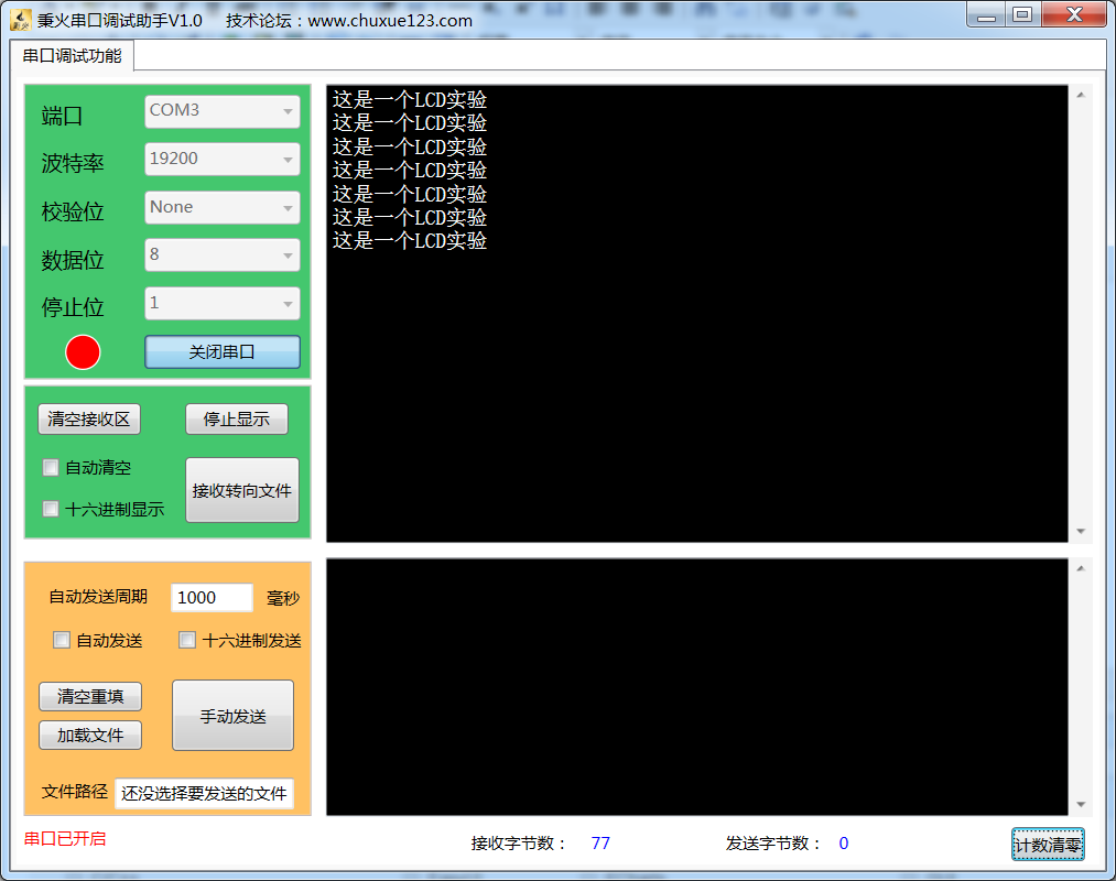
printf("这是一个LCD实验\r\n");
/* ILI9341初始化 */
ILI9341_GPIO_Init();
while(1);
}
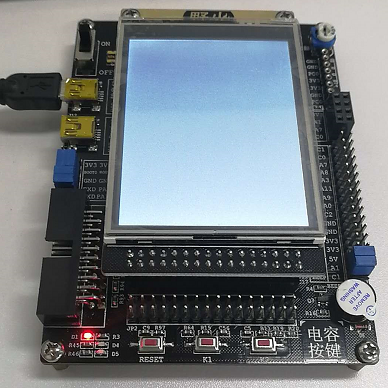
实验结果:
确认装好LCD液晶屏,将程序烧录到板子中,按下复位键RESET,屏幕就会被点亮。


 浙公网安备 33010602011771号