1_ZedBoard开发板测试
启动
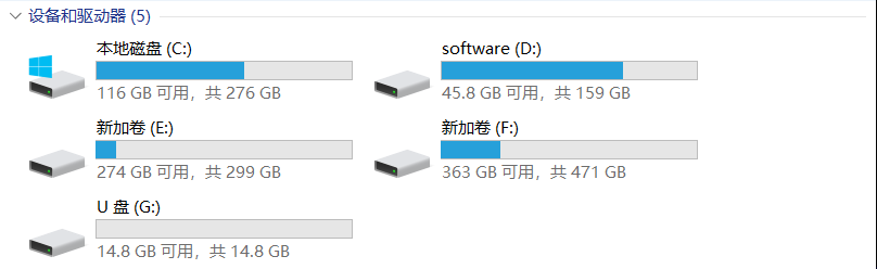
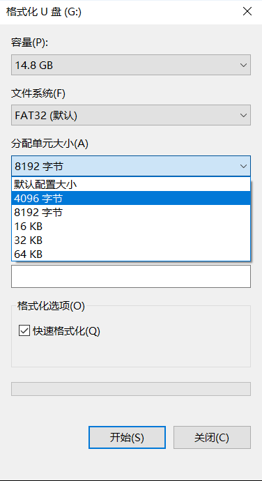
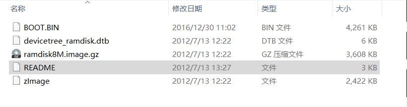
- 将SD卡插入电脑进行格式化
测试
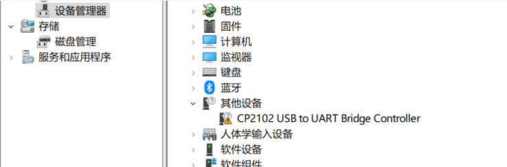
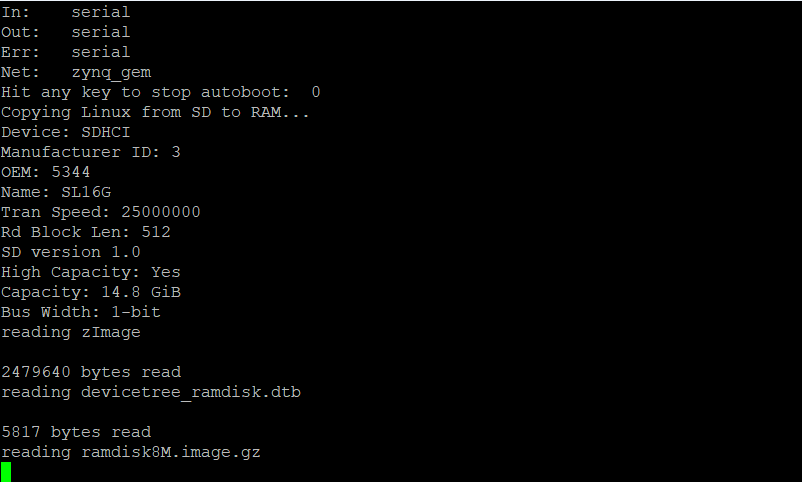
- 启动后,即可进行测试,首先测试以太网。用网线将zedboard和电脑直连,此时串口界面会提示以太网连接。


结语
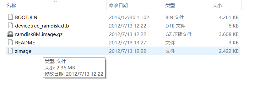
其实所有的测试内容都在zedboard文档内,该文档在第一步往SD卡里复制文件时就可以发现,在文件夹sd_image里。
The files on this SD card may be used to boot a simple Linux image with
functionality that demonstrates the basic capabilities of the ZED board.
To boot this image, first insert the SD card into the ZED board, and
ensure that the jumpers are set as follows:
MIO 6: set to GND
MIO 5: set to 3V3
MIO 4: set to 3V3
MIO 3: set to GND
MIO 2: set to GND
VADJ Select: Set to 1V8
JP6: shorted
JP2: shorted
All other jumpers should be left unshorted.
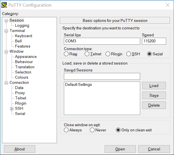
Attach a computer running a terminal emulator to the UART port with a
USB micro cable. Configure the terminal emulator as follows:
Baud : 115200
8 data bits
1 stop bit
no parity
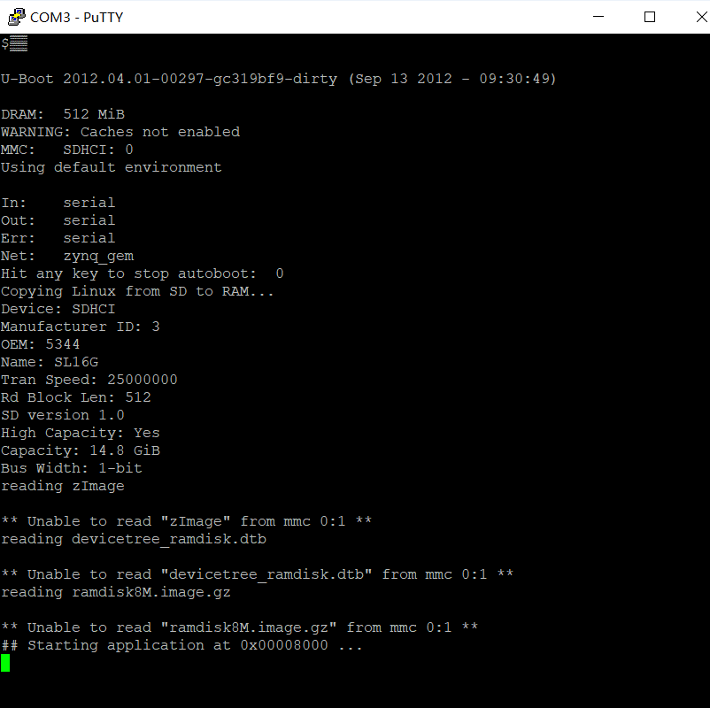
Attach a 12 V power supply to the ZED board and power it on. Connect to
the appropriate COM port in the terminal emulator. The boot process
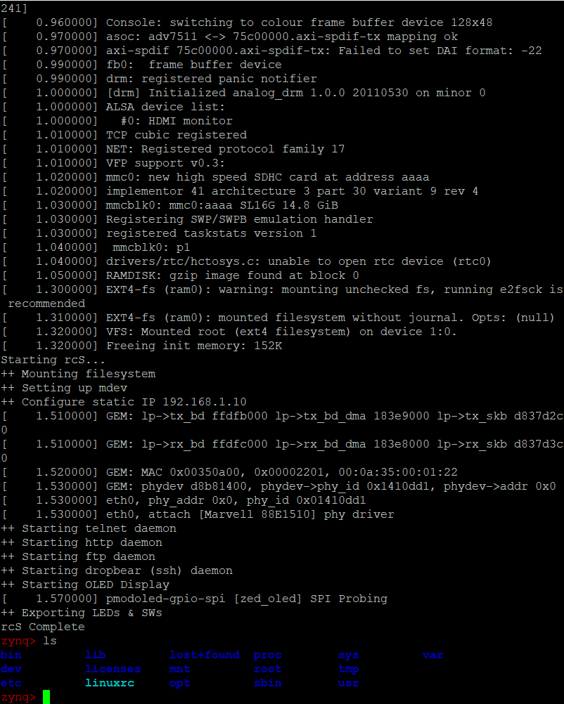
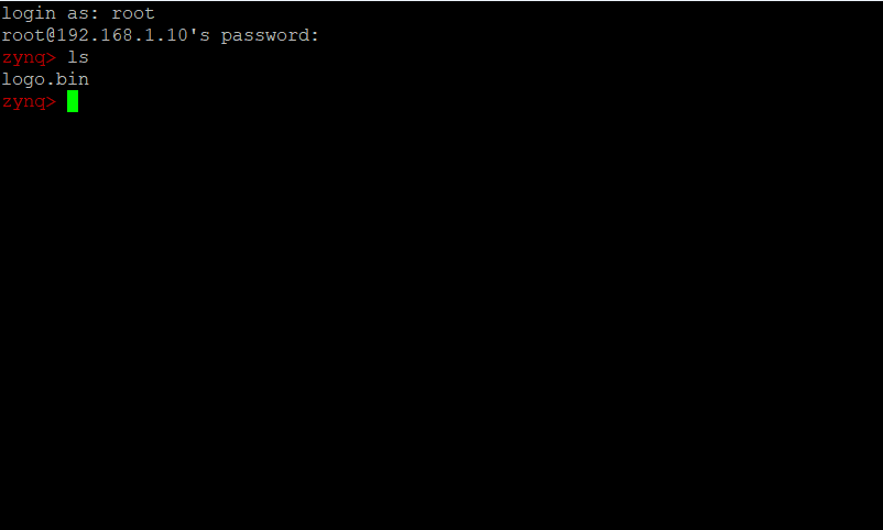
should finish in about a minute. You will know boot-up has completed
when pressing return at the terminal presents you with a red "zynq>"
prompt.
When you are done using Linux, you should run the command:
poweroff
and then switch off the ZED board.
- FEATURES *
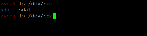
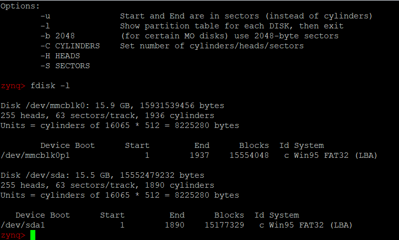
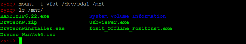
USB-OTG: To use USB devices with the ZED board, first connect a hub
to the USB-OTG port. USB devices attached to this hub can then be
accessed in Linux. USB thumbdrives attached in this manner can be
mounted with read/write access.
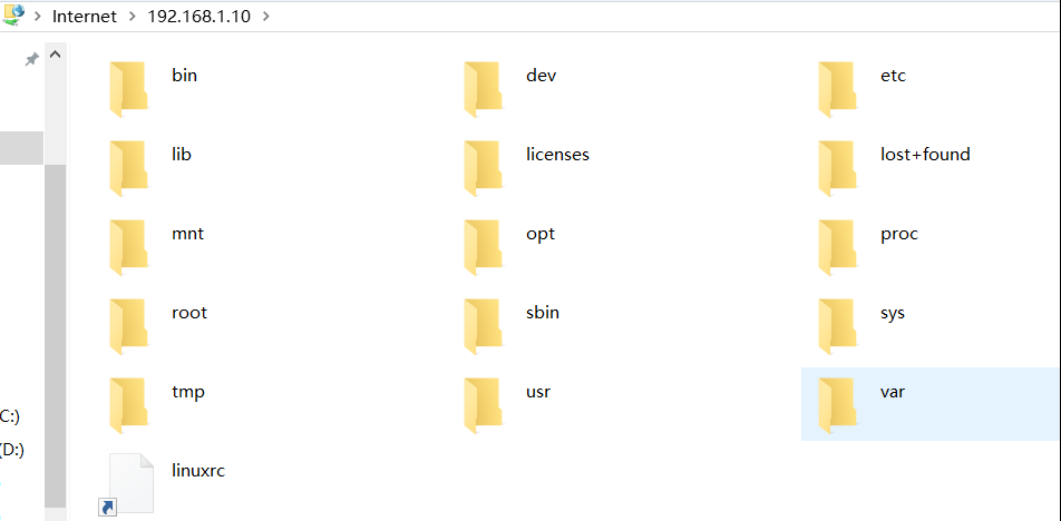
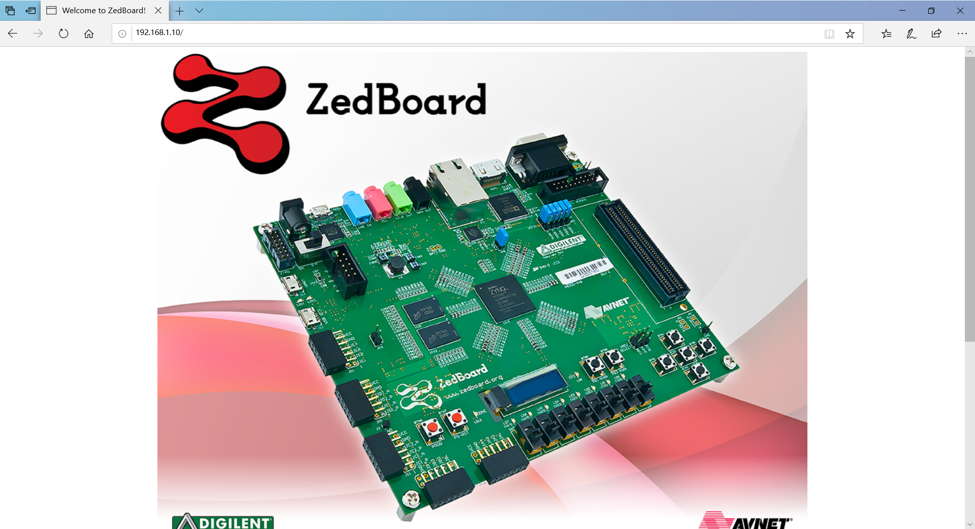
ETHERNET: After boot-up a dropbear ssh server, fttpd FTP server, and
a httpd HTTP server will be running. Refer to the documentation on
these servers if you are interested in using them. A default website
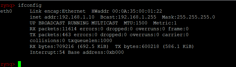
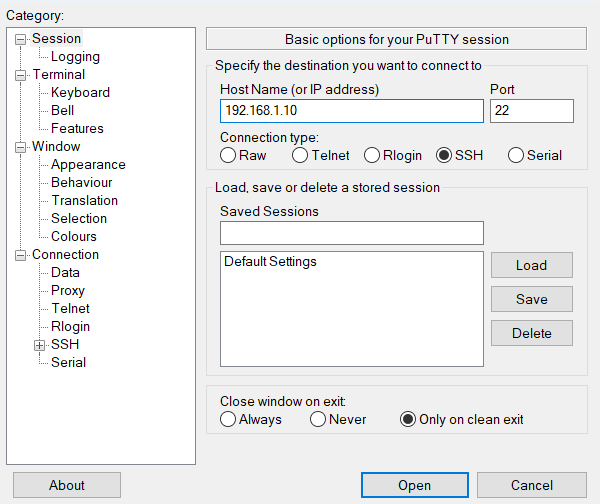
is hosted on the httpd server that can be reached at the static IP:
192.168.1.10.
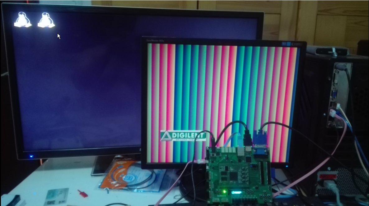
VGA: A test pattern is output on the VGA connector by the programmable
logic.
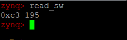
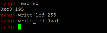
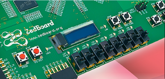
SWITCHES/LEDS: Scripts are included for writing to the LEDs and reading
the state of the switches. To read the state of the switches, run the
command:
read_sw
It will return the state of the switches as both hexadecimal and decimal.
A script for changing the state of the LEDs is also included. To turn all
8 LEDs on, run one of the following two commands:
write_led 255
write_led 0xFF
LD9 is used to indicate read/write activity on the SD card.
OLED DISPLAY: A default image is displayed on the OLED after Linux
has finished booting. In order to prolong the life of the OLED display,
the manufacturer suggests that a specific powerdown sequence be used.
Running the poweroff command before switching the ZED board off will
ensure that this procedure is correctly followed.
最后最后,记得关机下电之前使用poweroff指令关机。
<center><p>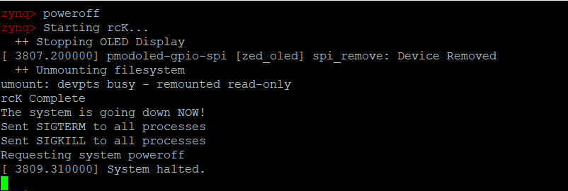</p></center>
然后愉快收工。
 浙公网安备 33010602011771号