
基于STM32的ModBus实现(一)移植FreeMODBUS RTU
一、FreeMODBUS
FreeModbus是一个开源的Modbus通信协议栈实现。它允许开发者在各种平台上轻松地实现Modbus通信功能,包括串口和以太网。FreeMODBUS提供了用于从设备和主站通信的功能,支持Modbus RTU和Modbus TCP协议。在工业控制和自动化领域广泛应用。
FreeModBus可通过官方网站下载:FreeMODBUS
下载到的文件如下:

- demo: 里面放置接口文件的模板和了一些示例代码
- doc: FreeModBus的说明文档
- modbus: modbus源码都在这个里面
- tools: 这个里面是测试modbus工具,不过还需要去下载一般不用,一般使用Modbus Poll工具调试ModBus。
二、STM32 移植ModBus RTU
移植ModBusRTU 比较简单,我这里也参考了别人写的博客STM32 移植FreeModbus详细过程,移植ModBusRTU的话看这一篇就够了,我这里也总结一下。
1、准备一个STM32的工程模板
工程模板最好是实现了串口通信,移植比较方便,我这里使用的单片机为STM32F407ZGT6,相应的串口和定时器的初始化与其他单片机(如STM32F103)略有不同。
2、将FreeModBus需要使用到的源文件添加到工程
modbus源文件的内容如下:
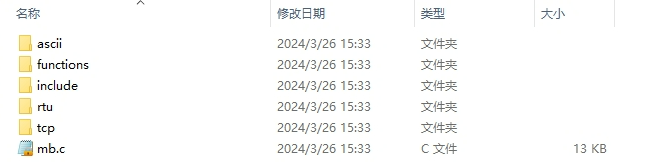
- ascii: ModBus ASCII源文件
- functions: ModBus源码函数文件
- include: 相关的头文件
- rtu: ModBus RTU文件
- tcp: ModBus TCP文件
移植ModBus RTU需要将ascii、functions、rtu和mb.c文件添加到工程的modbus文件夹下(在工程中新建一个modbus文件夹)
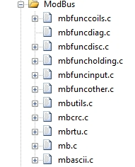
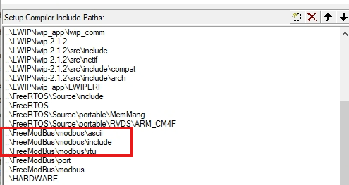
由于ascii、rtu中也有.h文件因此添加头文件路径时也要讲这两个文件夹加上
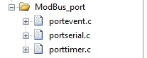
3、将接口文件的模板添加到工程并添加代码
接口文件模板使用demo\BARE\port文件夹中的接口模板,将port文件夹复制到工程中的modbus文件夹下并将其添加到工程
3.1 portserial.c文件
接下来就是向接口文件portserial.c文件中添加代码了,代码如下:
portserial.c
/*
 * FreeModbus Libary: BARE Port
 * Copyright (C) 2006 Christian Walter <wolti@sil.at>
 *
 * This library is free software; you can redistribute it and/or
 * modify it under the terms of the GNU Lesser General Public
 * License as published by the Free Software Foundation; either
 * version 2.1 of the License, or (at your option) any later version.
 *
 * This library is distributed in the hope that it will be useful,
 * but WITHOUT ANY WARRANTY; without even the implied warranty of
 * MERCHANTABILITY or FITNESS FOR A PARTICULAR PURPOSE.  See the GNU
 * Lesser General Public License for more details.
 *
 * You should have received a copy of the GNU Lesser General Public
 * License along with this library; if not, write to the Free Software
 * Foundation, Inc., 51 Franklin St, Fifth Floor, Boston, MA  02110-1301  USA
 *
 * File: $Id$
 */

#include "port.h"
#include "stm32f4xx.h"
#include "USART1/usart1.h"
#include "stdio.h"

/* ----------------------- Modbus includes ----------------------------------*/
#include "mb.h"
#include "mbport.h"

/* ----------------------- static functions ---------------------------------*/
static void prvvUARTTxReadyISR( void );
static void prvvUARTRxISR( void );

/* ----------------------- Start implementation -----------------------------*/
void
vMBPortSerialEnable( BOOL xRxEnable, BOOL xTxEnable )
{
    /* If xRXEnable enable serial receive interrupts. If xTxENable enable
     * transmitter empty interrupts.
     */
	//STM32串口接收中断使能
	if(xRxEnable == TRUE)
	{
		//UART中断使能
		USART_ITConfig(USART1, USART_IT_RXNE, ENABLE);
	}
	else
	{
	  //禁止接收和接收中断
		USART_ITConfig(USART1, USART_IT_RXNE, DISABLE);
	}
	//STM32串口发送中断使能
	if(xTxEnable == TRUE)
	{
	  //使能发送中断
		USART_ITConfig(USART1, USART_IT_TC, ENABLE);
	}
	else
	{
		//禁止发送中断
		USART_ITConfig(USART1, USART_IT_TC, DISABLE);
	}
}

BOOL
xMBPortSerialInit( UCHAR ucPORT, ULONG ulBaudRate, UCHAR ucDataBits, eMBParity eParity )
{
	//串口初始化
	USART1_Config((uint16_t)ulBaudRate);
	USART1_NVIC();
    return TRUE;
}

BOOL
xMBPortSerialPutByte( CHAR ucByte )
{
    /* Put a byte in the UARTs transmit buffer. This function is called
     * by the protocol stack if pxMBFrameCBTransmitterEmpty( ) has been
     * called. */
	//串口发送函数
	USART_SendData(USART1, ucByte);
    return TRUE;
}

BOOL
xMBPortSerialGetByte( CHAR * pucByte )
{
    /* Return the byte in the UARTs receive buffer. This function is called
     * by the protocol stack after pxMBFrameCBByteReceived( ) has been called.
     */
	//串口接收函数
	*pucByte = USART_ReceiveData(USART1);
    return TRUE;
}

/* Create an interrupt handler for the transmit buffer empty interrupt
 * (or an equivalent) for your target processor. This function should then
 * call pxMBFrameCBTransmitterEmpty( ) which tells the protocol stack that
 * a new character can be sent. The protocol stack will then call
 * xMBPortSerialPutByte( ) to send the character.
 */
static void prvvUARTTxReadyISR( void )
{
    pxMBFrameCBTransmitterEmpty(  );
}

/* Create an interrupt handler for the receive interrupt for your target
 * processor. This function should then call pxMBFrameCBByteReceived( ). The
 * protocol stack will then call xMBPortSerialGetByte( ) to retrieve the
 * character.
 */
static void prvvUARTRxISR( void )
{
    pxMBFrameCBByteReceived(  );
}

/**
  * @brief  This function handles usart1 Handler.
  * @param  None
  * @retval None
  */
//串口中断函数
void USART1_IRQHandler(void)
{
  //发生接收中断
  if(USART_GetITStatus(USART1, USART_IT_RXNE) == SET)
  {
    prvvUARTRxISR(); //串口接收中断调用函数
    //清除中断标志位
    USART_ClearITPendingBit(USART1, USART_IT_RXNE);
  }

	if(USART_GetITStatus(USART1, USART_IT_ORE) == SET)
  {
    USART_ClearITPendingBit(USART1, USART_IT_ORE);
	prvvUARTRxISR(); 	//串口发送中断调用函数
  }

  //发生完成中断
  if(USART_GetITStatus(USART1, USART_IT_TC) == SET)
  {
    prvvUARTTxReadyISR();
    //清除中断标志
    USART_ClearITPendingBit(USART1, USART_IT_TC);
  }
}
portserial.c文件主要封装了对串口的操作
vMBPortSerialEnable()   封装了接口(串口)的发送与接收使能\失能
xMBPortSerialInit()     接口(串口)的初始化
xMBPortSerialPutByte()  接口(串口)的发送函数
xMBPortSerialGetByte()  接口(串口)的接收函数
USART1_IRQHandler()     串口中断触发上面的接收与发送回调函数
调用的初始化函数如下
usart.c
#include "sys.h"
#include "USART1/usart1.h"

//初始化IO 串口1
//bound:波特率
void USART1_Config(uint16_t buad)
{
	//GPIO端口设置
	GPIO_InitTypeDef GPIO_InitStructure;
	USART_InitTypeDef USART_InitStructure;

	RCC_AHB1PeriphClockCmd(RCC_AHB1Periph_GPIOA,ENABLE); //使能GPIOA时钟
	RCC_APB2PeriphClockCmd(RCC_APB2Periph_USART1,ENABLE);//使能USART1时钟

	//串口1对应引脚复用映射
	GPIO_PinAFConfig(GPIOA,GPIO_PinSource9,GPIO_AF_USART1); //GPIOA9复用为USART1
	GPIO_PinAFConfig(GPIOA,GPIO_PinSource10,GPIO_AF_USART1); //GPIOA10复用为USART1

	//USART1端口配置
	GPIO_InitStructure.GPIO_Pin = GPIO_Pin_9 | GPIO_Pin_10; //GPIOA9与GPIOA10
	GPIO_InitStructure.GPIO_Mode = GPIO_Mode_AF;//复用功能
	GPIO_InitStructure.GPIO_Speed = GPIO_Speed_50MHz;	//速度50MHz
	GPIO_InitStructure.GPIO_OType = GPIO_OType_PP; //推挽复用输出
	GPIO_InitStructure.GPIO_PuPd = GPIO_PuPd_UP; //上拉
	GPIO_Init(GPIOA,&GPIO_InitStructure); //初始化PA9,PA10

	//USART1 初始化设置
	USART_InitStructure.USART_BaudRate = buad;//波特率设置
	USART_InitStructure.USART_WordLength = USART_WordLength_8b;//字长为8位数据格式
	USART_InitStructure.USART_StopBits = USART_StopBits_1;//一个停止位
	USART_InitStructure.USART_Parity = USART_Parity_No;//无奇偶校验位
	USART_InitStructure.USART_HardwareFlowControl = USART_HardwareFlowControl_None;//无硬件数据流控制
	USART_InitStructure.USART_Mode = USART_Mode_Rx | USART_Mode_Tx;	//收发模式
	USART_Init(USART1, &USART_InitStructure); //初始化串口1

	USART_Cmd(USART1, ENABLE);  //使能串口1


}
void USART1_NVIC(void)
{
  NVIC_InitTypeDef NVIC_InitStructure;

  /* 配置中断源 */
  NVIC_InitStructure.NVIC_IRQChannel = USART1_IRQn;
  NVIC_InitStructure.NVIC_IRQChannelPreemptionPriority = 5;
  NVIC_InitStructure.NVIC_IRQChannelSubPriority = 0;
  NVIC_InitStructure.NVIC_IRQChannelCmd = ENABLE;
  NVIC_Init(&NVIC_InitStructure);
}
usart.h
#ifndef __USART1_H
#define __USART1_H
#include "stm32f4xx_conf.h"
#include "sys.h"

void USART1_Config(uint16_t buad);
void USART1_NVIC(void);
#endif
3.2 porttimer.c
接下来修改porttimer.c文件,代码如下
porttimer.c
/*
 * FreeModbus Libary: BARE Port
 * Copyright (C) 2006 Christian Walter <wolti@sil.at>
 *
 * This library is free software; you can redistribute it and/or
 * modify it under the terms of the GNU Lesser General Public
 * License as published by the Free Software Foundation; either
 * version 2.1 of the License, or (at your option) any later version.
 *
 * This library is distributed in the hope that it will be useful,
 * but WITHOUT ANY WARRANTY; without even the implied warranty of
 * MERCHANTABILITY or FITNESS FOR A PARTICULAR PURPOSE.  See the GNU
 * Lesser General Public License for more details.
 *
 * You should have received a copy of the GNU Lesser General Public
 * License along with this library; if not, write to the Free Software
 * Foundation, Inc., 51 Franklin St, Fifth Floor, Boston, MA  02110-1301  USA
 *
 * File: $Id$
 */

/* ----------------------- Platform includes --------------------------------*/
#include "port.h"
#include "timer.h"
/* ----------------------- Modbus includes ----------------------------------*/
#include "mb.h"
#include "mbport.h"

/* ----------------------- static functions ---------------------------------*/
static void prvvTIMERExpiredISR( void );

/* ----------------------- Start implementation -----------------------------*/
BOOL
xMBPortTimersInit( USHORT usTim1Timerout50us )
{
	TIM3_Init(usTim1Timerout50us);
    return TRUE;
}


inline void
vMBPortTimersEnable(  )
{
    /* Enable the timer with the timeout passed to xMBPortTimersInit( ) */
	TIM_ClearITPendingBit(TIM3, TIM_IT_Update);
	TIM_ITConfig(TIM3, TIM_IT_Update, ENABLE);
	TIM_SetCounter(TIM3,0x0000);
	TIM_Cmd(TIM3, ENABLE);
}

inline void
vMBPortTimersDisable(  )
{
    /* Disable any pending timers. */
	  TIM_ClearITPendingBit(TIM3, TIM_IT_Update);
	  TIM_ITConfig(TIM3, TIM_IT_Update, DISABLE);
	  TIM_SetCounter(TIM3,0x0000);
	  TIM_Cmd(TIM3, DISABLE);
}

/* Create an ISR which is called whenever the timer has expired. This function
 * must then call pxMBPortCBTimerExpired( ) to notify the protocol stack that
 * the timer has expired.
 */
static void prvvTIMERExpiredISR( void )
{
    ( void )pxMBPortCBTimerExpired(  );
}

void TIM3_IRQHandler(void)
{
	if(TIM_GetITStatus(TIM3, TIM_IT_Update) != RESET)
	{
		prvvTIMERExpiredISR();
		TIM_ClearITPendingBit(TIM3, TIM_IT_Update);
	}
}
porttimer.c文件主要是初始化定时器、使能、失能和中断后的时间更新,比较简单。
定时器初始化函数如下(也可以使用其他的定时器比如系统定时器):
timer.c
#include "timer.h"
#include "led.h"

//通用定时器3中断初始化
//arr:自动重装值。
//psc:时钟预分频数
//定时器溢出时间计算方法:Tout=((arr+1)*(psc+1))/Ft us.
//Ft=定时器工作频率,单位:Mhz
//这里使用的是定时器3!
void TIM3_Init(u16 period)
{
   TIM_TimeBaseInitTypeDef TIM_TimeBaseInitStructure;
   NVIC_InitTypeDef NVIC_InitStructure;

   RCC_APB1PeriphClockCmd(RCC_APB1Periph_TIM3,ENABLE);  ///使能TIM3时钟

   TIM_TimeBaseInitStructure.TIM_Prescaler=period;  //定时器分频
   TIM_TimeBaseInitStructure.TIM_CounterMode=TIM_CounterMode_Up; //向上计数模式
   TIM_TimeBaseInitStructure.TIM_Period=(16800-1);   //自动重装载值
   TIM_TimeBaseInitStructure.TIM_ClockDivision=TIM_CKD_DIV1;

   TIM_TimeBaseInit(TIM3,&TIM_TimeBaseInitStructure);

//	TIM_ITConfig(TIM3,TIM_IT_Update,ENABLE); //允许定时器3更新中断
   TIM_Cmd(TIM3,ENABLE); //使能定时器3

   NVIC_InitStructure.NVIC_IRQChannel=TIM3_IRQn; //定时器3中断
   NVIC_InitStructure.NVIC_IRQChannelPreemptionPriority= 5; //抢占优先级0
   NVIC_InitStructure.NVIC_IRQChannelSubPriority= 0; //子优先级15
   NVIC_InitStructure.NVIC_IRQChannelCmd=ENABLE;
   NVIC_Init(&NVIC_InitStructure);

}
timer.h
#ifndef _TIMER_H
#define _TIMER_H
#include "sys.h"


void TIM3_Init(u16 period);
#endif
4、定义各模拟寄存器的参数以及补全相关的寄存器操作函数
4.1 各模拟寄存器的参数
这些只是测试的参数,实际项目需要根据相关的IO、传感器实时更新参数。
Register configuration
/* ----------------------- Defines ------------------------------------------*/
//输入寄存器起始地址
#define REG_INPUT_START       0x0000
//输入寄存器数量
#define REG_INPUT_NREGS       8
//保持寄存器起始地址
#define REG_HOLDING_START     0x0000
//保持寄存器数量
#define REG_HOLDING_NREGS     8

//线圈起始地址
#define REG_COILS_START       0x0000
//线圈数量
#define REG_COILS_SIZE        16

//开关寄存器起始地址
#define REG_DISCRETE_START    0x0000
//开关寄存器数量
#define REG_DISCRETE_SIZE     16

/* Private variables ---------------------------------------------------------*/
//输入寄存器内容
uint16_t usRegInputBuf[REG_INPUT_NREGS] = {0x1000,0x1001,0x1002,0x1003,0x1004,0x1005,0x1006,0x1007};
//输入寄存器起始地址
uint16_t usRegInputStart = REG_INPUT_START;

//保持寄存器内容
uint16_t usRegHoldingBuf[REG_HOLDING_NREGS] = {0x147b,0x3f8e,0x147b,0x400e,0x1eb8,0x4055,0x147b,0x408e};
//保持寄存器起始地址
uint16_t usRegHoldingStart = REG_HOLDING_START;

//线圈状态
uint8_t ucRegCoilsBuf[REG_COILS_SIZE / 8] = {0x0f,0x02};
//开关输入状态
uint8_t ucRegDiscreteBuf[REG_DISCRETE_SIZE / 8] = {0x0f,0x02};
4.2 读取输入寄存器 eMBRegInputCB()
eMBRegInputCB()
/****************************************************************************
* 名	  称:eMBRegInputCB
* 功    能:读取输入寄存器,对应功能码是 04 eMBFuncReadInputRegister
* 入口参数:pucRegBuffer: 数据缓存区,用于响应主机
*						usAddress: 寄存器地址
*						usNRegs: 要读取的寄存器个数
* 出口参数:
* 注	  意:上位机发来的 帧格式是: SlaveAddr(1 Byte)+FuncCode(1 Byte)
*								+StartAddrHiByte(1 Byte)+StartAddrLoByte(1 Byte)
*								+LenAddrHiByte(1 Byte)+LenAddrLoByte(1 Byte)+
*								+CRCAddrHiByte(1 Byte)+CRCAddrLoByte(1 Byte)
*							3 区
****************************************************************************/
eMBErrorCode
eMBRegInputCB( UCHAR * pucRegBuffer, USHORT usAddress, USHORT usNRegs )
{
   eMBErrorCode    eStatus = MB_ENOERR;
   int             iRegIndex;

   if( ( usAddress >= REG_INPUT_START )
       && ( usAddress + usNRegs <= REG_INPUT_START + REG_INPUT_NREGS ) )
   {
       iRegIndex = ( int )( usAddress - usRegInputStart );
       while( usNRegs > 0 )
       {
           *pucRegBuffer++ = ( UCHAR )( usRegInputBuf[iRegIndex] >> 8 );
           *pucRegBuffer++ = ( UCHAR )( usRegInputBuf[iRegIndex] & 0xFF );
           iRegIndex++;
           usNRegs--;
       }
   }
   else
   {
       eStatus = MB_ENOREG;
   }

   return eStatus;
}
4.3 保持寄存器操作函数 eMBRegHoldingCB()
eMBRegHoldingCB()
/****************************************************************************
* 名	  称:eMBRegHoldingCB
* 功    能:对应功能码有:06 写保持寄存器 eMBFuncWriteHoldingRegister
*													16 写多个保持寄存器 eMBFuncWriteMultipleHoldingRegister
*													03 读保持寄存器 eMBFuncReadHoldingRegister
*													23 读写多个保持寄存器 eMBFuncReadWriteMultipleHoldingRegister
* 入口参数:pucRegBuffer: 数据缓存区,用于响应主机
*						usAddress: 寄存器地址
*						usNRegs: 要读写的寄存器个数
*						eMode: 功能码
* 出口参数:
* 注	  意:4 区
****************************************************************************/
eMBErrorCode
eMBRegHoldingCB( UCHAR * pucRegBuffer, USHORT usAddress, USHORT usNRegs, eMBRegisterMode eMode )
{
	eMBErrorCode    eStatus = MB_ENOERR;
	int             iRegIndex;


	if((usAddress >= REG_HOLDING_START)&&\
		((usAddress+usNRegs) <= (REG_HOLDING_START + REG_HOLDING_NREGS)))
	{
		iRegIndex = (int)(usAddress - usRegHoldingStart);
		switch(eMode)
		{
			case MB_REG_READ://读 MB_REG_READ = 0
        while(usNRegs > 0)
				{
					*pucRegBuffer++ = (u8)(usRegHoldingBuf[iRegIndex] >> 8);
					*pucRegBuffer++ = (u8)(usRegHoldingBuf[iRegIndex] & 0xFF);
          iRegIndex++;
          usNRegs--;
				}
        break;
			case MB_REG_WRITE://写 MB_REG_WRITE = 0
				while(usNRegs > 0)
				{
					usRegHoldingBuf[iRegIndex] = *pucRegBuffer++ << 8;
          usRegHoldingBuf[iRegIndex] |= *pucRegBuffer++;
          iRegIndex++;
          usNRegs--;
        }
			}
	}
	else//错误
	{
		eStatus = MB_ENOREG;
	}

	return eStatus;
}
4.4 线圈操作函数 eMBRegCoilsCB()
eMBRegCoilsCB()
extern void xMBUtilSetBits( UCHAR * ucByteBuf, USHORT usBitOffset, UCHAR ucNBits,
                UCHAR ucValue );
extern UCHAR xMBUtilGetBits( UCHAR * ucByteBuf, USHORT usBitOffset, UCHAR ucNBits );
/****************************************************************************
* 名	  称:eMBRegCoilsCB
* 功    能:对应功能码有:01 读线圈 eMBFuncReadCoils
*													05 写线圈 eMBFuncWriteCoil
*													15 写多个线圈 eMBFuncWriteMultipleCoils
* 入口参数:pucRegBuffer: 数据缓存区,用于响应主机
*						usAddress: 线圈地址
*						usNCoils: 要读写的线圈个数
*						eMode: 功能码
* 出口参数:
* 注	  意:如继电器
*						0 区
****************************************************************************/
eMBErrorCode
eMBRegCoilsCB( UCHAR * pucRegBuffer, USHORT usAddress, USHORT usNCoils,
              eMBRegisterMode eMode )
{
  //错误状态
  eMBErrorCode eStatus = MB_ENOERR;
  //寄存器个数
  int16_t iNCoils = ( int16_t )usNCoils;
  //寄存器偏移量
  int16_t usBitOffset;

  //检查寄存器是否在指定范围内
  if( ( (int16_t)usAddress >= REG_COILS_START ) &&
     ( usAddress + usNCoils <= REG_COILS_START + REG_COILS_SIZE ) )
  {
    //计算寄存器偏移量
    usBitOffset = ( int16_t )( usAddress - REG_COILS_START );
    switch ( eMode )
    {
      //读操作
    case MB_REG_READ:
      while( iNCoils > 0 )
      {
        *pucRegBuffer++ = xMBUtilGetBits( ucRegCoilsBuf, usBitOffset,
                                         ( uint8_t )( iNCoils > 8 ? 8 : iNCoils ) );
        iNCoils -= 8;
        usBitOffset += 8;
      }
      break;

      //写操作
    case MB_REG_WRITE:
      while( iNCoils > 0 )
      {
        xMBUtilSetBits( ucRegCoilsBuf, usBitOffset,
                       ( uint8_t )( iNCoils > 8 ? 8 : iNCoils ),
                       *pucRegBuffer++ );
        iNCoils -= 8;
      }
      break;
    }

  }
  else
  {
    eStatus = MB_ENOREG;
  }
  return eStatus;
}
4.5 离散寄存器操作函数 eMBRegDiscreteCB()
eMBRegDiscreteCB()
/****************************************************************************
* 名	  称:eMBRegDiscreteCB
* 功    能:读取离散寄存器,对应功能码有:02 读离散寄存器 eMBFuncReadDiscreteInputs
* 入口参数:pucRegBuffer: 数据缓存区,用于响应主机
*						usAddress: 寄存器地址
*						usNDiscrete: 要读取的寄存器个数
* 出口参数:
* 注	  意:1 区
****************************************************************************/
eMBErrorCode
eMBRegDiscreteCB( UCHAR * pucRegBuffer, USHORT usAddress, USHORT usNDiscrete )
{
  //错误状态
  eMBErrorCode eStatus = MB_ENOERR;
  //操作寄存器个数
  int16_t iNDiscrete = ( int16_t )usNDiscrete;
  //偏移量
  uint16_t usBitOffset;

  //判断寄存器时候再制定范围内
  if( ( (int16_t)usAddress >= REG_DISCRETE_START ) &&
     ( usAddress + usNDiscrete <= REG_DISCRETE_START + REG_DISCRETE_SIZE ) )
  {
    //获得偏移量
    usBitOffset = ( uint16_t )( usAddress - REG_DISCRETE_START );

    while( iNDiscrete > 0 )
    {
      *pucRegBuffer++ = xMBUtilGetBits( ucRegDiscreteBuf, usBitOffset,
                                       ( uint8_t)( iNDiscrete > 8 ? 8 : iNDiscrete ) );
      iNDiscrete -= 8;
      usBitOffset += 8;
    }

  }
  else
  {
    eStatus = MB_ENOREG;
  }
  return eStatus;
}
5、FreeMODBUS源文件的一些修改
5.1、mbconfig.h文件
当前使用的为ModBus RTU 将默认的ModBus ASCII 取消
/*! \brief If Modbus ASCII support is enabled. */
#define MB_ASCII_ENABLED                        (  0 )

/*! \brief If Modbus RTU support is enabled. */
#define MB_RTU_ENABLED                          (  1 )

/*! \brief If Modbus TCP support is enabled. */
#define MB_TCP_ENABLED                          (  0 )

/*! \brief The character timeout value for Modbus ASCII.
*
* The character timeout value is not fixed for Modbus ASCII and is therefore
* a configuration option. It should be set to the maximum expected delay
* time of the network.
*/
#define MB_ASCII_TIMEOUT_SEC                    (  0 )
5.2、mbrtu.c文件
eMBRTUSend()
eMBErrorCode
eMBRTUSend( UCHAR ucSlaveAddress, const UCHAR * pucFrame, USHORT usLength )
{
    eMBErrorCode    eStatus = MB_ENOERR;
    USHORT          usCRC16;

    ENTER_CRITICAL_SECTION(  );

    /* Check if the receiver is still in idle state. If not we where to
     * slow with processing the received frame and the master sent another
     * frame on the network. We have to abort sending the frame.
     */
    if( eRcvState == STATE_RX_IDLE )
    {
        /* First byte before the Modbus-PDU is the slave address. */
        pucSndBufferCur = ( UCHAR * ) pucFrame - 1;
        usSndBufferCount = 1;

        /* Now copy the Modbus-PDU into the Modbus-Serial-Line-PDU. */
        pucSndBufferCur[MB_SER_PDU_ADDR_OFF] = ucSlaveAddress;
        usSndBufferCount += usLength;

        /* Calculate CRC16 checksum for Modbus-Serial-Line-PDU. */
        usCRC16 = usMBCRC16( ( UCHAR * ) pucSndBufferCur, usSndBufferCount );
        ucRTUBuf[usSndBufferCount++] = ( UCHAR )( usCRC16 & 0xFF );
        ucRTUBuf[usSndBufferCount++] = ( UCHAR )( usCRC16 >> 8 );

        /* Activate the transmitter. */
        eSndState = STATE_TX_XMIT;

		//修改了从这里往下
		//启动第一次发送,这样才可以进入发送完成中断
        xMBPortSerialPutByte( ( CHAR )*pucSndBufferCur );
        pucSndBufferCur++;  /* next byte in sendbuffer. */
        usSndBufferCount--;

        vMBPortSerialEnable( FALSE, TRUE );
    }
    else
    {
        eStatus = MB_EIO;
    }
    EXIT_CRITICAL_SECTION(  );
    return eStatus;
}
5.3 usRegAddress++ 的地址自增
以下文件中的usRegAddress++会导致读写是的地址自增,可以将以下文件中的usRegAddress++注释掉
mbfunccoils.c
mbfuncdisc.c
mbfuncholding.c
mbfuncinput.c
6、main.c函数中初始化并启动ModBus
接下来结束在main.c函数中启动modbus RTU了。
eMBInit()       初始化modbus
eMBEnable()     使能modbus
eMbPoll()       查询事件状态
	printf("Err : %d\n",eMBInit(MB_RTU, 0x01, 0x01, 9600, MB_PAR_NONE));//初始化freemodbus 设置RTU模式和ID等
	eMBEnable();

    while(1)
	{
		eMBPoll();
		vTaskDelay(10);
	}
eMBInit()的原型为
eMBErrorCodeeMBInit( eMBMode eMode, UCHAR ucSlaveAddress, UCHAR ucPort, ULONG ulBaudRate, eMBParity eParity )

eMode: modbus模式 MB_RTU、MB_ASCII
ucSlaveAddress: 从机地址
ucPort: 连接的端口号(如串口连接电脑的端口号,当前测试被忽略了无效)
ulBaudRate: 连接串口的波特率
eParity: 校验方式(MB_PAR_NONE、MB_PAR_ODD、MB_PAR_EVEN)
我的程序使用的FreeRTOS操作系统,将查询事件作为一个线程,还有一个modbus输入寄存器更新的线程,用于在测试时能看到寄存器数据的变化。
注:main.c文件中的lwip、dp83848的相关文件是用于之后移植modbus TCP使用的,这些文件对当前的modbus RTU不会造成影响。
完整main.c文件如下
main.c
#include "sys.h"
#include "delay.h"
#include "usart.h"
#include "led.h"
#include "timer.h"
#include "lwip/timeouts.h"
#include "stm32f4x7_eth.h"
#include "DP83848.h"

#include "lwip_comm.h"

/*FreeModBus*/
#include "mb.h"
#include "mbutils.h"

#if SYSTEM_SUPPORT_OS
#include "FreeRTOS.h"
#include "task.h"
#endif /*SYSTEM_SUPPORT_OS*/

/* ----------------------- Defines ------------------------------------------*/
//输入寄存器起始地址
#define REG_INPUT_START       0x0000
//输入寄存器数量
#define REG_INPUT_NREGS       8
//保持寄存器起始地址
#define REG_HOLDING_START     0x0000
//保持寄存器数量
#define REG_HOLDING_NREGS     8

//线圈起始地址
#define REG_COILS_START       0x0000
//线圈数量
#define REG_COILS_SIZE        16

//开关寄存器起始地址
#define REG_DISCRETE_START    0x0000
//开关寄存器数量
#define REG_DISCRETE_SIZE     16

/* Private variables ---------------------------------------------------------*/
//输入寄存器内容
uint16_t usRegInputBuf[REG_INPUT_NREGS] = {0x1000,0x1001,0x1002,0x1003,0x1004,0x1005,0x1006,0x1007};
//输入寄存器起始地址
uint16_t usRegInputStart = REG_INPUT_START;

//保持寄存器内容
uint16_t usRegHoldingBuf[REG_HOLDING_NREGS] = {0x147b,0x3f8e,0x147b,0x400e,0x1eb8,0x4055,0x147b,0x408e};
//保持寄存器起始地址
uint16_t usRegHoldingStart = REG_HOLDING_START;

//线圈状态
uint8_t ucRegCoilsBuf[REG_COILS_SIZE / 8] = {0x0f,0x02};
//开关输入状态
uint8_t ucRegDiscreteBuf[REG_DISCRETE_SIZE / 8] = {0x0f,0x02};


/*开始任务*/
TaskHandle_t StartTask_Handler;
void start_task(void *pvParameters);
/*LED任务*/
TaskHandle_t LED0Task_Handler;
void led0_task(void *pvParameters);

/**************************FreeModBus******************************/
/*ModBus任务*/
TaskHandle_t ModBus_TASK_STK_Handler;
void ModBus_task(void *pvParameters);
/*ModBus输入任务*/
TaskHandle_t ModBus_Input_TASK_Handler;
void ModBus_Input_task(void *pvParameters);
/******************************************************************/


#if SYSTEM_SUPPORT_OS
int main(void)
{
    NVIC_PriorityGroupConfig(NVIC_PriorityGroup_4); // 中断分组配置
    delay_init(168);                                // 初始化延时函数
	LED_Init();
    uart_init();                              		// 初始化串口
	printf("Err : %d\n",eMBInit(MB_RTU, 0x01, 0x01, 9600, MB_PAR_NONE));//初始化freemodbus 设置RTU模式和ID等
	eMBEnable();

                                  // 初始化LED端口
//	TIM3_Int_Init(999, 839);
	/*创建开始任务*/
    xTaskCreate((TaskFunction_t )start_task,            //任务函数
                (const char*    )"start_task",          //任务名称
                (uint16_t       )256,       			//任务堆栈大小
                (void*          )NULL,                  //传递给任务函数的参数
                (UBaseType_t    )1,       				//任务优先级
                (TaskHandle_t*  )&StartTask_Handler);   //任务句柄
	/*开启任务调度*/
	vTaskStartScheduler();
    while (1)
    {
//		sys_check_timeouts();
    }
}

/*开始任务任务函数*/
void start_task(void *pvParameters)
{
	lwip_comm_init();
    taskENTER_CRITICAL();           //进入临界区
    //创建LED0任务
    xTaskCreate((TaskFunction_t )led0_task,
                (const char*    )"led0_task",
                (uint16_t       )64,
                (void*          )NULL,
                (UBaseType_t    )2,
                (TaskHandle_t*  )&LED0Task_Handler);
	//ModBus任务
    xTaskCreate((TaskFunction_t )ModBus_task,
                (const char*    )"modbus_task",
                (uint16_t       )256,
                (void*          )NULL,
                (UBaseType_t    )3,
                (TaskHandle_t*  )&ModBus_TASK_STK_Handler);
	//ModBus输入任务
    xTaskCreate((TaskFunction_t )ModBus_Input_task,
                (const char*    )"modbus_input_task",
                (uint16_t       )256,
                (void*          )NULL,
                (UBaseType_t    )4,
                (TaskHandle_t*  )&ModBus_Input_TASK_Handler);
    vTaskDelete(StartTask_Handler); //删除开始任务
    taskEXIT_CRITICAL();            //退出临界区
}

/*LED0任务函数*/
void led0_task(void *pvParameters)
{
    while(1)
    {
        LED0=~LED0;
        vTaskDelay(500);
    }
}

//ModBus任务
void ModBus_task(void *pdata)
{
	while(1)
	{
		eMBPoll();
		vTaskDelay(10);

	}
}
//ModBus输入寄存器任务
void ModBus_Input_task(void *pdata)
{
	while(1)
	{
		if(usRegInputBuf[0] > 0x1050)
		{
			usRegInputBuf[0] = 0x1000;
		}
		else
			usRegInputBuf[0] = usRegInputBuf[0] + (u16)1;
		vTaskDelay(1000);

	}
}


/****************************************************************************
* 名	  称:eMBRegInputCB
* 功    能:读取输入寄存器,对应功能码是 04 eMBFuncReadInputRegister
* 入口参数:pucRegBuffer: 数据缓存区,用于响应主机
*						usAddress: 寄存器地址
*						usNRegs: 要读取的寄存器个数
* 出口参数:
* 注	  意:上位机发来的 帧格式是: SlaveAddr(1 Byte)+FuncCode(1 Byte)
*								+StartAddrHiByte(1 Byte)+StartAddrLoByte(1 Byte)
*								+LenAddrHiByte(1 Byte)+LenAddrLoByte(1 Byte)+
*								+CRCAddrHiByte(1 Byte)+CRCAddrLoByte(1 Byte)
*							3 区
****************************************************************************/
eMBErrorCode
eMBRegInputCB( UCHAR * pucRegBuffer, USHORT usAddress, USHORT usNRegs )
{
    eMBErrorCode    eStatus = MB_ENOERR;
    int             iRegIndex;

    if( ( usAddress >= REG_INPUT_START )
        && ( usAddress + usNRegs <= REG_INPUT_START + REG_INPUT_NREGS ) )
    {
        iRegIndex = ( int )( usAddress - usRegInputStart );
        while( usNRegs > 0 )
        {
            *pucRegBuffer++ = ( UCHAR )( usRegInputBuf[iRegIndex] >> 8 );
            *pucRegBuffer++ = ( UCHAR )( usRegInputBuf[iRegIndex] & 0xFF );
            iRegIndex++;
            usNRegs--;
        }
    }
    else
    {
        eStatus = MB_ENOREG;
    }

    return eStatus;
}

/****************************************************************************
* 名	  称:eMBRegHoldingCB
* 功    能:对应功能码有:06 写保持寄存器 eMBFuncWriteHoldingRegister
*													16 写多个保持寄存器 eMBFuncWriteMultipleHoldingRegister
*													03 读保持寄存器 eMBFuncReadHoldingRegister
*													23 读写多个保持寄存器 eMBFuncReadWriteMultipleHoldingRegister
* 入口参数:pucRegBuffer: 数据缓存区,用于响应主机
*						usAddress: 寄存器地址
*						usNRegs: 要读写的寄存器个数
*						eMode: 功能码
* 出口参数:
* 注	  意:4 区
****************************************************************************/
eMBErrorCode
eMBRegHoldingCB( UCHAR * pucRegBuffer, USHORT usAddress, USHORT usNRegs, eMBRegisterMode eMode )
{
	eMBErrorCode    eStatus = MB_ENOERR;
	int             iRegIndex;


	if((usAddress >= REG_HOLDING_START)&&\
		((usAddress+usNRegs) <= (REG_HOLDING_START + REG_HOLDING_NREGS)))
	{
		iRegIndex = (int)(usAddress - usRegHoldingStart);
		switch(eMode)
		{
			case MB_REG_READ://读 MB_REG_READ = 0
        while(usNRegs > 0)
				{
					*pucRegBuffer++ = (u8)(usRegHoldingBuf[iRegIndex] >> 8);
					*pucRegBuffer++ = (u8)(usRegHoldingBuf[iRegIndex] & 0xFF);
          iRegIndex++;
          usNRegs--;
				}
        break;
			case MB_REG_WRITE://写 MB_REG_WRITE = 0
				while(usNRegs > 0)
				{
					usRegHoldingBuf[iRegIndex] = *pucRegBuffer++ << 8;
          usRegHoldingBuf[iRegIndex] |= *pucRegBuffer++;
          iRegIndex++;
          usNRegs--;
        }
			}
	}
	else//错误
	{
		eStatus = MB_ENOREG;
	}

	return eStatus;
}

extern void xMBUtilSetBits( UCHAR * ucByteBuf, USHORT usBitOffset, UCHAR ucNBits,
                UCHAR ucValue );
extern UCHAR xMBUtilGetBits( UCHAR * ucByteBuf, USHORT usBitOffset, UCHAR ucNBits );
/****************************************************************************
* 名	  称:eMBRegCoilsCB
* 功    能:对应功能码有:01 读线圈 eMBFuncReadCoils
*													05 写线圈 eMBFuncWriteCoil
*													15 写多个线圈 eMBFuncWriteMultipleCoils
* 入口参数:pucRegBuffer: 数据缓存区,用于响应主机
*						usAddress: 线圈地址
*						usNCoils: 要读写的线圈个数
*						eMode: 功能码
* 出口参数:
* 注	  意:如继电器
*						0 区
****************************************************************************/
eMBErrorCode
eMBRegCoilsCB( UCHAR * pucRegBuffer, USHORT usAddress, USHORT usNCoils,
              eMBRegisterMode eMode )
{
  //错误状态
  eMBErrorCode eStatus = MB_ENOERR;
  //寄存器个数
  int16_t iNCoils = ( int16_t )usNCoils;
  //寄存器偏移量
  int16_t usBitOffset;

  //检查寄存器是否在指定范围内
  if( ( (int16_t)usAddress >= REG_COILS_START ) &&
     ( usAddress + usNCoils <= REG_COILS_START + REG_COILS_SIZE ) )
  {
    //计算寄存器偏移量
    usBitOffset = ( int16_t )( usAddress - REG_COILS_START );
    switch ( eMode )
    {
      //读操作
    case MB_REG_READ:
      while( iNCoils > 0 )
      {
        *pucRegBuffer++ = xMBUtilGetBits( ucRegCoilsBuf, usBitOffset,
                                         ( uint8_t )( iNCoils > 8 ? 8 : iNCoils ) );
        iNCoils -= 8;
        usBitOffset += 8;
      }
      break;

      //写操作
    case MB_REG_WRITE:
      while( iNCoils > 0 )
      {
        xMBUtilSetBits( ucRegCoilsBuf, usBitOffset,
                       ( uint8_t )( iNCoils > 8 ? 8 : iNCoils ),
                       *pucRegBuffer++ );
        iNCoils -= 8;
      }
      break;
    }

  }
  else
  {
    eStatus = MB_ENOREG;
  }
  return eStatus;
}

/****************************************************************************
* 名	  称:eMBRegDiscreteCB
* 功    能:读取离散寄存器,对应功能码有:02 读离散寄存器 eMBFuncReadDiscreteInputs
* 入口参数:pucRegBuffer: 数据缓存区,用于响应主机
*						usAddress: 寄存器地址
*						usNDiscrete: 要读取的寄存器个数
* 出口参数:
* 注	  意:1 区
****************************************************************************/
eMBErrorCode
eMBRegDiscreteCB( UCHAR * pucRegBuffer, USHORT usAddress, USHORT usNDiscrete )
{
  //错误状态
  eMBErrorCode eStatus = MB_ENOERR;
  //操作寄存器个数
  int16_t iNDiscrete = ( int16_t )usNDiscrete;
  //偏移量
  uint16_t usBitOffset;

  //判断寄存器时候再制定范围内
  if( ( (int16_t)usAddress >= REG_DISCRETE_START ) &&
     ( usAddress + usNDiscrete <= REG_DISCRETE_START + REG_DISCRETE_SIZE ) )
  {
    //获得偏移量
    usBitOffset = ( uint16_t )( usAddress - REG_DISCRETE_START );

    while( iNDiscrete > 0 )
    {
      *pucRegBuffer++ = xMBUtilGetBits( ucRegDiscreteBuf, usBitOffset,
                                       ( uint8_t)( iNDiscrete > 8 ? 8 : iNDiscrete ) );
      iNDiscrete -= 8;
      usBitOffset += 8;
    }

  }
  else
  {
    eStatus = MB_ENOREG;
  }
  return eStatus;
}
6、连接电脑使用ModBus Poll 软件进行测试
在程序编译没问题后使用ModBus Poll软件进行ModBus 通讯测试。
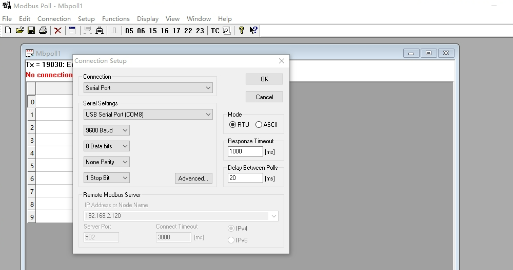
使用串口转usb模块将串口连接到电脑,打开ModBus Poll软件,点击connection配置如下:
Connection : Serial Port
Serial Setting : COMx(当前连接的端口)
Baud : 9600 (Modbus初始化时的参数)
其他如下图,配置完成后OK
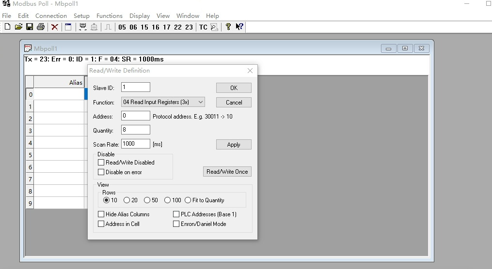
选择Setup-Read/Write Definition
SlaveID : 初始化时的从机地址(本例配置为 0x01)
Function : 04 Read Input Registers (读取输入寄存器,我们添加了一个更新输入寄存器的线程,读取时会看到相关数据的变化)
Address : 起始地址,代码中配置为0x0000
Quantity : 读取的寄存器数量(不能超过程序中配置的数量8)
其他参数如下图
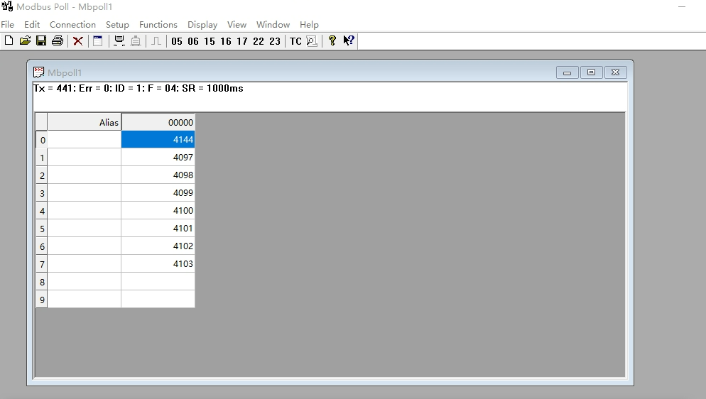
配置完成后会自动读取相关寄存器的值如下
7、ending
本节完成了STM32 移植ModBus RTU,会在下一章实现 STM32 + Lwip2.1.2 + DP83848 + FreeRTOS + ModBus TCP的移植。

 浙公网安备 33010602011771号