CH58x/CH57x硬件SPI操作外部flash学习记录
官方提供的58x的spi例程,spi主机模式下的发送方式有三种单字节发送,FIFO连续发送,DMA连续发送。本文分别对SPI0主机模式下三种发送模式进行使用。
本次使用的是CH582m做为主机,W25Q64FV作为从机。
一、单字节发送
本次调试中实现对W25Q64FVflas进行读id,擦除,写入,读取。
在进行主要操作的时候先理清代码逻辑。主机先将SCS总线拉低,保证能够开始接收数据。再通过W25Q64FV的手册我们知道在进行操作之前要判断当前是否在
忙碌状态。如果不在忙碌状态将进行下一步。通过手册我们可以知道通过发送对应的地址(0x05or0x35)进行判忙。
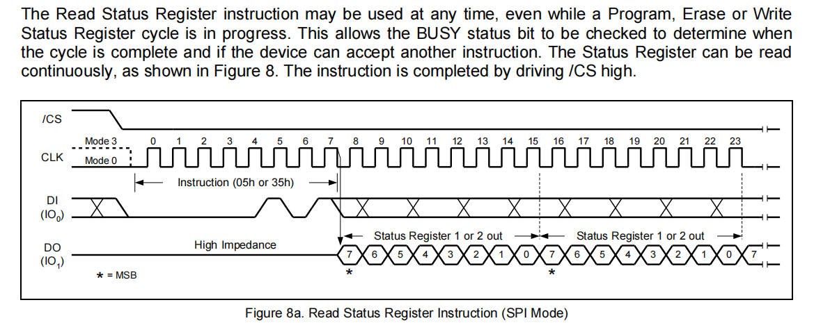
程序中实现判断忙碌的操作可见如下:
void SPI_Flash_Wait_Busy(void)
{
    uint8_t busy;
    do
    {
        GPIOA_ResetBits(GPIO_Pin_12);
        SPI0_MasterSendByte(0x05);

        busy=SPI0_MasterRecvByte();
        GPIOA_SetBits(GPIO_Pin_12);

        PRINT("busy%02x\r\n",busy);
    }
    while((busy&0x01)==0x01);

}
接下来基本就按照需要使用的器件的手册进行读写等操作:
(1)、读ID:
读ID看是否能够读到正确的设备ID:
#define W25Q80 0XEF13
#define W25Q16 0XEF14
#define W25Q32 0XEF15
#define W25Q64 0XEF16
#define W25Q128 0XEF17
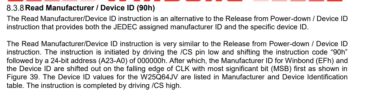
我们读ID根据手册的提示需要对就相应的寄存器地址进行操作;程序演示如下所示:
void read_wq64_id(void)
{
    uint8_t ID1,ID2;
    GPIOA_ResetBits(GPIO_Pin_12);
    SPI0_MasterSendByte(0x90);
    SPI0_MasterSendByte(0x00);
    SPI0_MasterSendByte(0x00);
    SPI0_MasterSendByte(0x00);
    ID1=SPI0_MasterRecvByte();
    ID2=SPI0_MasterRecvByte();
    GPIOA_SetBits(GPIO_Pin_12);

    PRINT("%02x\r\n %02x\r\n ",ID1,ID2);

}
读取到的数据是EF16证明读取的ID没有问题。如果是其他的值可以在程序加判断直到是自己使用器件的ID再在进行下面的操作;
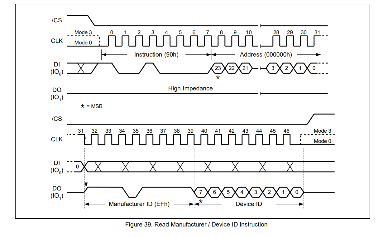
(2)、擦除扇区
在写之前要对对应的扇区进行擦除,
从手册上可以看出是4k擦除,还要注意在指令之后有24bit地址的操作,写入20h后需要进行移位操作,详情可见程序
手册中有这样一句话:A Write Enable instruction must be executed before the device will accept the Sector Erase Instruction (Status Register bit WEL must equal 1)。在进行擦除操作之前需要写使能:
所以擦除之前需要进行写使能:对应时序操作如下

代码实现:
void SPI_Write_Enable(void)
{
    GPIOA_ResetBits(GPIO_Pin_12);
    SPI0_MasterSendByte(0x06);
    GPIOA_SetBits(GPIO_Pin_12);

}
下面的则是擦除部分的代码:
void erase_sector(uint32_t SectorAddress)
{
    SectorAddress *= 4096;
    SPI_Write_Enable();
    SPI_Flash_Wait_Busy();
    GPIOA_ResetBits(GPIO_Pin_12);
    SPI0_MasterSendByte(0x20);

    SPI0_MasterSendByte((uint8_t)(SectorAddress>>16));
    SPI0_MasterSendByte((uint8_t)(SectorAddress>>8));
    SPI0_MasterSendByte((uint8_t)SectorAddress);
    GPIOA_SetBits(GPIO_Pin_12);

}
(3)读操作,
进行读操作的情况下;读的操作稍微方便一些不需要进行判忙写使能等操作

在进行读操作的时,注意时序图中有一个Data Out 1,此时会有输出
void read_wq64_data(uint8_t instruction,uint32_t ReadAddr,uint16_t ReadByteNum,uint8_t *p_Buffer)
{
     uint16_t i;
     GPIOA_ResetBits(GPIO_Pin_12);
     SPI0_MasterSendByte(instruction);
     SPI0_MasterSendByte((uint8_t)(ReadAddr>>16));
     SPI0_MasterSendByte((uint8_t)(ReadAddr>>8));
     SPI0_MasterSendByte((uint8_t)ReadAddr);

     for(i = 0; i < ReadByteNum; i++)
     {
         p_Buffer[i] = SPI0_MasterRecvByte();

     }
     GPIOA_SetBits(GPIO_Pin_12);

}
(5)写操作;
本次写入是按页写入,写之前先看手册注意手册中需要操作的部分
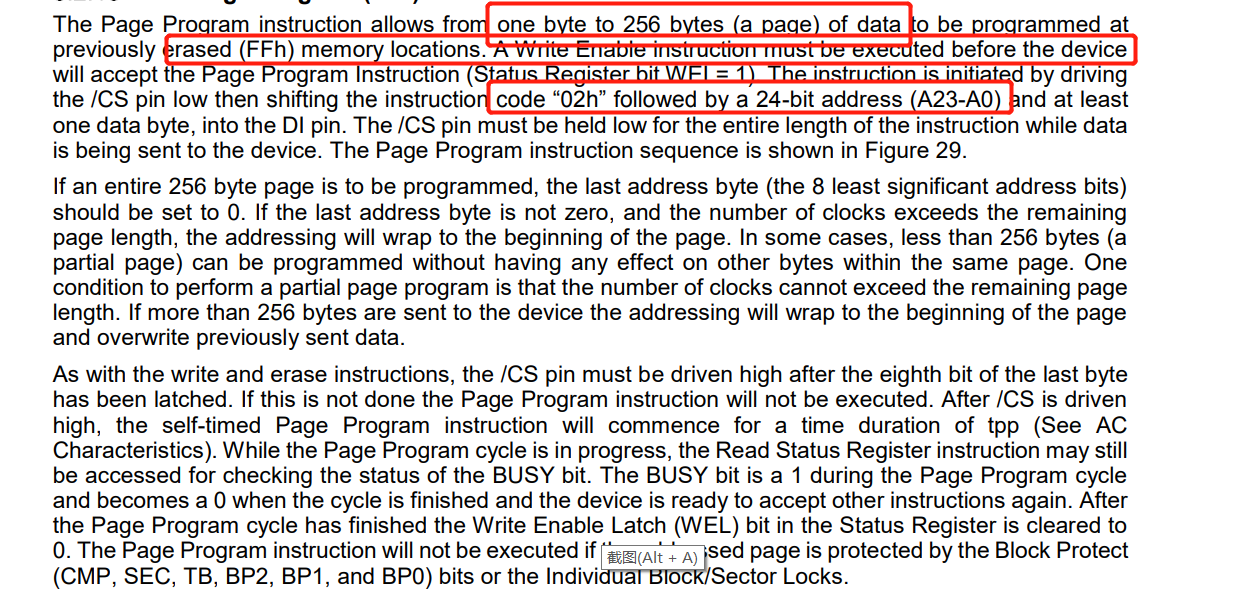
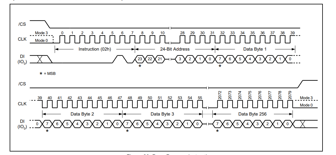
对应程序如下所示:
void  write_wq64_page_data(uint8_t *p_Buffer,uint32_t PageAddress,uint16_t WriteByteNum)
{
    SPI_Write_Enable();

    GPIOA_ResetBits(GPIO_Pin_12);
    SPI0_MasterSendByte(0x02);
    SPI0_MasterSendByte((uint8_t)(PageAddress>>16));
    SPI0_MasterSendByte((uint8_t)(PageAddress>>8));
    SPI0_MasterSendByte((uint8_t)PageAddress);
    if(WriteByteNum > 256)
    {
        WriteByteNum=256;
        PRINT("\r\n Err");
    }
    while(WriteByteNum--)
    {
        SPI0_MasterSendByte(*p_Buffer);
        p_Buffer++;
    }
    GPIOA_SetBits(GPIO_Pin_12);
    SPI_Flash_Wait_Busy();
}
差不多一个流程就是如此;可以在程序中加入打印或者使用逻辑分析仪等辅助工具对现象进行查看。
准备写入的数据__attribute__((aligned(4))) UINT8 spiBuff[] = {2, 2, 3, 3, 5, 6, 7, 8, 9, 0, 1, 2, 3, 4, 5, 6};读出的结果如下

本次操作关键是对片选信号线的操作与对不同指令的读写操作,具体按照手册的时序的操作来即可。
仅是个人学习分享;如有任何错漏敬请留言指正。

 浙公网安备 33010602011771号