[译]Vulkan教程(14)图形管道基础之固定功能
[译]Vulkan教程(14)图形管道基础之固定功能
Fixed functions 固定功能
The older graphics APIs provided default state for most of the stages of the graphics pipeline. In Vulkan you have to be explicit about everything, from viewport size to color blending function. In this chapter we'll fill in all of the structures to configure these fixed-function operations.
旧有的图形API提供默认状态for大多数图形管道的阶段。Vulkan中你必须显式地声明所有东西,从视口大小到颜色混合函数。本章我们将填入所有这些结构体to配置这些固定功能的操作。
Vertex input 顶点输入
The VkPipelineVertexInputStateCreateInfo structure describes the format of the vertex data that will be passed to the vertex shader. It describes this in roughly two ways:
- Bindings: spacing between data and whether the data is per-vertex or per-instance (see instancing)
- Attribute descriptions: type of the attributes passed to the vertex shader, which binding to load them from and at which offset
VkPipelineVertexInputStateCreateInfo 结构体描述了顶点数据的格式that会被传送到顶点shader。它一般用2种方式描述:
- 绑定:数据之间的间隔and数据是逐顶点还是逐instance(见instancing)
- 属性描述:传入顶点shader的属性的类型,从哪个绑定点加载它们,偏移量是多少。
Because we're hard coding the vertex data directly in the vertex shader, we'll fill in this structure to specify that there is no vertex data to load for now. We'll get back to it in the vertex buffer chapter.
因为我们直接在顶点shader硬编码了顶点数据,我们将填入这个结构体to指定没有顶点数据要要在。我们将在顶点buffer章节回头细究这个问题。
VkPipelineVertexInputStateCreateInfo vertexInputInfo = {};
vertexInputInfo.sType = VK_STRUCTURE_TYPE_PIPELINE_VERTEX_INPUT_STATE_CREATE_INFO;
vertexInputInfo.vertexBindingDescriptionCount = 0;
vertexInputInfo.pVertexBindingDescriptions = nullptr; // Optional
vertexInputInfo.vertexAttributeDescriptionCount = 0;
vertexInputInfo.pVertexAttributeDescriptions = nullptr; // Optional
The pVertexBindingDescriptions and pVertexAttributeDescriptions members point to an array of structs that describe the aforementioned details for loading vertex data. Add this structure to the createGraphicsPipelinefunction right after the shaderStages array.
pVertexBindingDescriptions 和pVertexAttributeDescriptions 成员指向一个结构体数组that描述前述加载顶点数据的细节。添加这个结构体到createGraphicsPipelinefunction函数-在shaderStages 数组之后。
Input assembly 输入组装
The VkPipelineInputAssemblyStateCreateInfo struct describes two things: what kind of geometry will be drawn from the vertices and if primitive restart should be enabled. The former is specified in the topology member and can have values like:
VK_PRIMITIVE_TOPOLOGY_POINT_LIST: points from verticesVK_PRIMITIVE_TOPOLOGY_LINE_LIST: line from every 2 vertices without reuseVK_PRIMITIVE_TOPOLOGY_LINE_STRIP: the end vertex of every line is used as start vertex for the next lineVK_PRIMITIVE_TOPOLOGY_TRIANGLE_LIST: triangle from every 3 vertices without reuseVK_PRIMITIVE_TOPOLOGY_TRIANGLE_STRIP: the second and third vertex of every triangle are used as first two vertices of the next triangle
VkPipelineInputAssemblyStateCreateInfo 结构体描述2件事:用顶点绘制哪种几何体and是否启用图元重启。前者在topology 成员中指定,可能的值包括:
VK_PRIMITIVE_TOPOLOGY_POINT_LIST:用顶点绘制点。VK_PRIMITIVE_TOPOLOGY_LINE_LIST:每2个顶点绘制一条线,不重用顶点。VK_PRIMITIVE_TOPOLOGY_LINE_STRIP:每条线的后一个顶点用作下一条线的第一个顶点。VK_PRIMITIVE_TOPOLOGY_TRIANGLE_LIST:每3个顶点绘制一个三角形。VK_PRIMITIVE_TOPOLOGY_TRIANGLE_STRIP:每个三角形的第2、3个顶点用作下一个三角形的第1、2个顶点。
Normally, the vertices are loaded from the vertex buffer by index in sequential order, but with an element buffer you can specify the indices to use yourself. This allows you to perform optimizations like reusing vertices. If you set the primitiveRestartEnable member to VK_TRUE, then it's possible to break up lines and triangles in the _STRIP topology modes by using a special index of 0xFFFF or 0xFFFFFFFF.
一般的,顶点按照在顶点buffer中的索引顺序被加载,但是用你可以指定要用的索引顺序。这允许你实施优化-例如复用顶点。如果你设置primitiveRestartEnable 成员为VK_TRUE,那么就可以打破在_STRIP 拓扑模式下的线和三角形by使用一个特殊索引值of0xFFFF 或0xFFFFFFFF。
We intend to draw triangles throughout this tutorial, so we'll stick to the following data for the structure:
本教程中我们偏爱绘制三角形,所以我们继续使用下述数据:
VkPipelineInputAssemblyStateCreateInfo inputAssembly = {};
inputAssembly.sType = VK_STRUCTURE_TYPE_PIPELINE_INPUT_ASSEMBLY_STATE_CREATE_INFO;
inputAssembly.topology = VK_PRIMITIVE_TOPOLOGY_TRIANGLE_LIST;
inputAssembly.primitiveRestartEnable = VK_FALSE;
Viewports and scissors 视口和裁剪
A viewport basically describes the region of the framebuffer that the output will be rendered to. This will almost always be (0, 0) to (width, height) and in this tutorial that will also be the case.
视口描述帧缓存的区域that输出会被渲染到的地方。这几乎总是(0, 0)到(width, height),本教程中也是如此。
VkViewport viewport = {};
viewport.x = 0.0f;
viewport.y = 0.0f;
viewport.width = (float) swapChainExtent.width;
viewport.height = (float) swapChainExtent.height;
viewport.minDepth = 0.0f;
viewport.maxDepth = 1.0f;
Remember that the size of the swap chain and its images may differ from the WIDTH and HEIGHT of the window. The swap chain images will be used as framebuffers later on, so we should stick to their size.
记住,交换链及其image的大小可能与窗口的WIDTH 和HEIGHT 不同。交换链image会被用到帧缓存中,所以我们应该stick它们的大小。
The minDepth and maxDepth values specify the range of depth values to use for the framebuffer. These values must be within the [0.0f, 1.0f] range, but minDepth may be higher than maxDepth. If you aren't doing anything special, then you should stick to the standard values of 0.0f and 1.0f.
minDepth 和maxDepth 值指定深度的范围for帧缓存。这些值必须在[0.0f, 1.0f]范围内,但是minDepth 可以比maxDepth高。如果你没有在做什么特别的事,那么就应该保持标准的值of0.0f和1.0f。
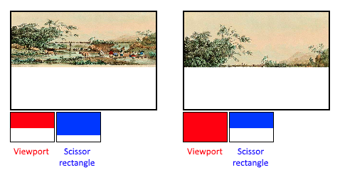
While viewports define the transformation from the image to the framebuffer, scissor rectangles define in which regions pixels will actually be stored. Any pixels outside the scissor rectangles will be discarded by the rasterizer. They function like a filter rather than a transformation. The difference is illustrated below. Note that the left scissor rectangle is just one of the many possibilities that would result in that image, as long as it's larger than the viewport.
视口定义了从image到帧缓存的变化,裁剪定义了哪个区域的像素会被保存。任何裁切区域外部的像素都会被光栅器忽略。它们更像是个过滤器。两者的区别如下。注意左边的裁剪区域只是许多可能性之一,只要它比视口大,就会导致图中的效果。
In this tutorial we simply want to draw to the entire framebuffer, so we'll specify a scissor rectangle that covers it entirely:
本教程中我们简单地想要绘制整个帧缓存,所以我们指定裁剪区域覆盖整个帧缓存:
VkRect2D scissor = {};
scissor.offset = {0, 0};
scissor.extent = swapChainExtent;
Now this viewport and scissor rectangle need to be combined into a viewport state using the VkPipelineViewportStateCreateInfo struct. It is possible to use multiple viewports and scissor rectangles on some graphics cards, so its members reference an array of them. Using multiple requires enabling a GPU feature (see logical device creation).
现在视口和裁剪信息需要被组合进一个视口状态结构体VkPipelineViewportStateCreateInfo 。在某些图形卡上使用多个视口和裁剪区域是可能的,所以它的成员是个数组。使用多个视口要求一个GPU特性(见逻辑设备创建)。
VkPipelineViewportStateCreateInfo viewportState = {};
viewportState.sType = VK_STRUCTURE_TYPE_PIPELINE_VIEWPORT_STATE_CREATE_INFO;
viewportState.viewportCount = 1;
viewportState.pViewports = &viewport;
viewportState.scissorCount = 1;
viewportState.pScissors = &scissor;
Rasterizer 光栅器
The rasterizer takes the geometry that is shaped by the vertices from the vertex shader and turns it into fragments to be colored by the fragment shader. It also performs depth testing, face culling and the scissor test, and it can be configured to output fragments that fill entire polygons or just the edges (wireframe rendering). All this is configured using the VkPipelineRasterizationStateCreateInfo structure.
光栅器接收几何体that由顶点构成from顶点shader,将其转换为Fragment to被Fragment shader上色。它也实施depth testing、face culling和裁剪测试,也可以配置它to输出Fragment填满多边形or只描边(线框渲染)。所有这些都用VkPipelineRasterizationStateCreateInfo 结构体来配置。
VkPipelineRasterizationStateCreateInfo rasterizer = {};
rasterizer.sType = VK_STRUCTURE_TYPE_PIPELINE_RASTERIZATION_STATE_CREATE_INFO;
rasterizer.depthClampEnable = VK_FALSE;
If depthClampEnable is set to VK_TRUE, then fragments that are beyond the near and far planes are clamped to them as opposed to discarding them. This is useful in some special cases like shadow maps. Using this requires enabling a GPU feature.
如果depthClampEnable 设置为VK_TRUE,那么在near和far面范围外的Fragment会被压到near或far面上,而不是忽略它们。这在某些特殊情况下是有用的-例如阴影贴图。使用它需要启用一个GPU特性。
rasterizer.rasterizerDiscardEnable = VK_FALSE;
If rasterizerDiscardEnable is set to VK_TRUE, then geometry never passes through the rasterizer stage. This basically disables any output to the framebuffer.
如果rasterizerDiscardEnable 设置为VK_TRUE,那么几何体就永远不会通过光栅化阶段。这基本上禁止了到帧缓存的输出。
rasterizer.polygonMode = VK_POLYGON_MODE_FILL;
The polygonMode determines how fragments are generated for geometry. The following modes are available:
VK_POLYGON_MODE_FILL: fill the area of the polygon with fragmentsVK_POLYGON_MODE_LINE: polygon edges are drawn as linesVK_POLYGON_MODE_POINT: polygon vertices are drawn as points
polygonMode 决定几何体怎样生成Fragment。下述模式可选:
VK_POLYGON_MODE_FILL:用Fragment填充多边形区域。VK_POLYGON_MODE_LINE:只画多边形的边框线。VK_POLYGON_MODE_POINT:用点画多边形的顶点。
Using any mode other than fill requires enabling a GPU feature.
使用除FILL外的模型都需要启用一个GPU特性。
rasterizer.lineWidth = 1.0f;
The lineWidth member is straightforward, it describes the thickness of lines in terms of number of fragments. The maximum line width that is supported depends on the hardware and any line thicker than 1.0f requires you to enable the wideLines GPU feature.
lineWidth 成员十分直观,它描述线的宽度,以像素为单位。支持的最大线宽度依赖于硬件,任何比1.0f更窄的宽度都需要启用GPU特性wideLines 。
rasterizer.cullMode = VK_CULL_MODE_BACK_BIT;
rasterizer.frontFace = VK_FRONT_FACE_CLOCKWISE;
The cullMode variable determines the type of face culling to use. You can disable culling, cull the front faces, cull the back faces or both. The frontFace variable specifies the vertex order for faces to be considered front-facing and can be clockwise or counterclockwise.
cullMode 变量决定了面剔除方式。你可以禁用剔除、剔除front面、剔除back面或都剔除。frontFace 变量指定面的顶点顺序to被认为是front面的是顺时针还是逆时针。
rasterizer.depthBiasEnable = VK_FALSE;
rasterizer.depthBiasConstantFactor = 0.0f; // Optional
rasterizer.depthBiasClamp = 0.0f; // Optional
rasterizer.depthBiasSlopeFactor = 0.0f; // Optional
The rasterizer can alter the depth values by adding a constant value or biasing them based on a fragment's slope. This is sometimes used for shadow mapping, but we won't be using it. Just set depthBiasEnable to VK_FALSE.
光栅器可以修改深度值by增加常量or基于Fragment的倾斜度偏移之。这有时用于阴影映射,但是我们不用它。设置depthBiasEnable 为VK_FALSE即可。
Multisampling 多重采样
The VkPipelineMultisampleStateCreateInfo struct configures multisampling, which is one of the ways to perform anti-aliasing. It works by combining the fragment shader results of multiple polygons that rasterize to the same pixel. This mainly occurs along edges, which is also where the most noticeable aliasing artifacts occur. Because it doesn't need to run the fragment shader multiple times if only one polygon maps to a pixel, it is significantly less expensive than simply rendering to a higher resolution and then downscaling. Enabling it requires enabling a GPU feature.
VkPipelineMultisampleStateCreateInfo 结构体配置多重采样,which是实施anti-aliasing的一种方法。它是将光栅化到同一个像素上的多个Fragment shader结果结合起来。这主要发生在边沿上,which也是最显眼的锯齿出现的地方。因为它不需要多次运行Fragment shader if只有1个多边形映射到一个像素上,它显著地耗费少than简单地渲染更高解析度然后缩放。启用它需要启用一个GPU特性。
VkPipelineMultisampleStateCreateInfo multisampling = {};
multisampling.sType = VK_STRUCTURE_TYPE_PIPELINE_MULTISAMPLE_STATE_CREATE_INFO;
multisampling.sampleShadingEnable = VK_FALSE;
multisampling.rasterizationSamples = VK_SAMPLE_COUNT_1_BIT;
multisampling.minSampleShading = 1.0f; // Optional
multisampling.pSampleMask = nullptr; // Optional
multisampling.alphaToCoverageEnable = VK_FALSE; // Optional
multisampling.alphaToOneEnable = VK_FALSE; // Optional
We'll revisit multisampling in later chapter, for now let's keep it disabled.
我们将在后续章节再谈多重采样,目前就禁用它吧。
Depth and stencil testing 深度和模版测试
If you are using a depth and/or stencil buffer, then you also need to configure the depth and stencil tests using VkPipelineDepthStencilStateCreateInfo. We don't have one right now, so we can simply pass a nullptr instead of a pointer to such a struct. We'll get back to it in the depth buffering chapter.
如果你要使用深度或模版缓存,那么你就需要配置深度和模板测试-用VkPipelineDepthStencilStateCreateInfo。现在我们没有,所以传入nullptr ,而不是结构体。我们将在深度buffer章节再谈它。
Color blending 颜色混合
After a fragment shader has returned a color, it needs to be combined with the color that is already in the framebuffer. This transformation is known as color blending and there are two ways to do it:
- Mix the old and new value to produce a final color
- Combine the old and new value using a bitwise operation
在Fragment shader返回颜色之后,它需要与帧缓存上已有的颜色组合。这被称为颜色混合,有2种实现方法:
- 混合新旧颜色,产生新颜色。
- 用位操作组合新旧颜色。
There are two types of structs to configure color blending. The first struct, VkPipelineColorBlendAttachmentState contains the configuration per attached framebuffer and the second struct, VkPipelineColorBlendStateCreateInfo contains the global color blending settings. In our case we only have one framebuffer:
有2种类型的结构体to配置颜色混合。第一个VkPipelineColorBlendAttachmentState,包含逐帧缓存的配置,第二个VkPipelineColorBlendStateCreateInfo,包含全局颜色混合配置。在我们的案例中我们只有1个帧缓存。
VkPipelineColorBlendAttachmentState colorBlendAttachment = {};
colorBlendAttachment.colorWriteMask = VK_COLOR_COMPONENT_R_BIT | VK_COLOR_COMPONENT_G_BIT | VK_COLOR_COMPONENT_B_BIT | VK_COLOR_COMPONENT_A_BIT;
colorBlendAttachment.blendEnable = VK_FALSE;
colorBlendAttachment.srcColorBlendFactor = VK_BLEND_FACTOR_ONE; // Optional
colorBlendAttachment.dstColorBlendFactor = VK_BLEND_FACTOR_ZERO; // Optional
colorBlendAttachment.colorBlendOp = VK_BLEND_OP_ADD; // Optional
colorBlendAttachment.srcAlphaBlendFactor = VK_BLEND_FACTOR_ONE; // Optional
colorBlendAttachment.dstAlphaBlendFactor = VK_BLEND_FACTOR_ZERO; // Optional
colorBlendAttachment.alphaBlendOp = VK_BLEND_OP_ADD; // Optional
This per-framebuffer struct allows you to configure the first way of color blending. The operations that will be performed are best demonstrated using the following pseudocode:
逐帧缓存的结构体允许你按第一种方式配置颜色混合。这样会实施的操作可以用下述伪代码最好的描述出来:
if (blendEnable) {
    finalColor.rgb = (srcColorBlendFactor * newColor.rgb) <colorBlendOp> (dstColorBlendFactor * oldColor.rgb);
    finalColor.a = (srcAlphaBlendFactor * newColor.a) <alphaBlendOp> (dstAlphaBlendFactor * oldColor.a);
} else {
    finalColor = newColor;
}

finalColor = finalColor & colorWriteMask;
If blendEnable is set to VK_FALSE, then the new color from the fragment shader is passed through unmodified. Otherwise, the two mixing operations are performed to compute a new color. The resulting color is AND'd with the colorWriteMask to determine which channels are actually passed through.
如果blendEnable 设置为VK_FALSE,那么新颜色会直接被送到帧缓存。否则,新旧颜色就会被混合以计算出最新的颜色。这个结果会与colorWriteMask
进行AND操作to决定哪个通道能够通过。
The most common way to use color blending is to implement alpha blending, where we want the new color to be blended with the old color based on its opacity. The finalColor should then be computed as follows:
最常见的颜色混合的使用方式是,实现alpha混合,where我们让新旧颜色依据其不透明度进行混合。finalColor 应当按如下方式计算:
finalColor.rgb = newAlpha * newColor + (1 - newAlpha) * oldColor;
finalColor.a = newAlpha.a;
This can be accomplished with the following parameters:
这可以用下述参数实现:
colorBlendAttachment.blendEnable = VK_TRUE;
colorBlendAttachment.srcColorBlendFactor = VK_BLEND_FACTOR_SRC_ALPHA;
colorBlendAttachment.dstColorBlendFactor = VK_BLEND_FACTOR_ONE_MINUS_SRC_ALPHA;
colorBlendAttachment.colorBlendOp = VK_BLEND_OP_ADD;
colorBlendAttachment.srcAlphaBlendFactor = VK_BLEND_FACTOR_ONE;
colorBlendAttachment.dstAlphaBlendFactor = VK_BLEND_FACTOR_ZERO;
colorBlendAttachment.alphaBlendOp = VK_BLEND_OP_ADD;
You can find all of the possible operations in the VkBlendFactor and VkBlendOp enumerations in the specification.
你可以在VkBlendFactor 和VkBlendOp 枚举类型中找到所有可能的操作in说明书中。
The second structure references the array of structures for all of the framebuffers and allows you to set blend constants that you can use as blend factors in the aforementioned calculations.
第二个结构体指向一个数组for所有的帧缓存,允许你设置混合常量that你可以用作混合因子in前述计算。
VkPipelineColorBlendStateCreateInfo colorBlending = {};
colorBlending.sType = VK_STRUCTURE_TYPE_PIPELINE_COLOR_BLEND_STATE_CREATE_INFO;
colorBlending.logicOpEnable = VK_FALSE;
colorBlending.logicOp = VK_LOGIC_OP_COPY; // Optional
colorBlending.attachmentCount = 1;
colorBlending.pAttachments = &colorBlendAttachment;
colorBlending.blendConstants[0] = 0.0f; // Optional
colorBlending.blendConstants[1] = 0.0f; // Optional
colorBlending.blendConstants[2] = 0.0f; // Optional
colorBlending.blendConstants[3] = 0.0f; // Optional
If you want to use the second method of blending (bitwise combination), then you should set logicOpEnable to VK_TRUE. The bitwise operation can then be specified in the logicOp field. Note that this will automatically disable the first method, as if you had set blendEnable to VK_FALSE for every attached framebuffer! The colorWriteMask will also be used in this mode to determine which channels in the framebuffer will actually be affected. It is also possible to disable both modes, as we've done here, in which case the fragment colors will be written to the framebuffer unmodified.
如果你想用第二种混合方式(位组合),那么你应当设置logicOpEnable 为VK_TRUE。然后就可以在logicOp 字段指定位操作了。注意,这会自动禁用第一种方法,就好像你设置了blendEnable 为VK_FALSE for每个附着的帧缓存一样!colorWriteMask 也会被用与此模式to决定帧缓存中哪个通道会受影响。也可以同时禁用这两种模式,我们就是这样做的,此时Fragment颜色会直接写入帧缓存中。
Dynamic state 动态状态
A limited amount of the state that we've specified in the previous structs can actually be changed without recreating the pipeline. Examples are the size of the viewport, line width and blend constants. If you want to do that, then you'll have to fill in a VkPipelineDynamicStateCreateInfo structure like this:
有那么少数几种状态that我们在之前章节指定的-可以在不重建管道的情况下被修改。粒子是视口大小,线宽度和混合常量。如果你想那么做,你必须像这样填入VkPipelineDynamicStateCreateInfo 结构体:
VkDynamicState dynamicStates[] = {
    VK_DYNAMIC_STATE_VIEWPORT,
    VK_DYNAMIC_STATE_LINE_WIDTH
};

VkPipelineDynamicStateCreateInfo dynamicState = {};
dynamicState.sType = VK_STRUCTURE_TYPE_PIPELINE_DYNAMIC_STATE_CREATE_INFO;
dynamicState.dynamicStateCount = 2;
dynamicState.pDynamicStates = dynamicStates;
This will cause the configuration of these values to be ignored and you will be required to specify the data at drawing time. We'll get back to this in a future chapter. This struct can be substituted by a nullptr later on if you don't have any dynamic state.
这会导致这些值的配置被忽略,你必须在绘制时指定数据。我们在后续章节再讨论之。这个结构体可以被nullptr 替换if你没有任何动态状态。
Pipeline layout 管道布局
You can use uniform values in shaders, which are globals similar to dynamic state variables that can be changed at drawing time to alter the behavior of your shaders without having to recreate them. They are commonly used to pass the transformation matrix to the vertex shader, or to create texture samplers in the fragment shader.
你可以在shader中用uniform 值,which是全局变量,与动态状态变量相似,可以在绘制时修改to调节shader的行为without重建shader。它们常用于传递变换矩阵to顶点shader,or创建纹理采样器in Fragment shader。
These uniform values need to be specified during pipeline creation by creating a VkPipelineLayout object. Even though we won't be using them until a future chapter, we are still required to create an empty pipeline layout.
这些uniform值需要在管道创建过程中被指定by创建一个VkPipelineLayout 对象。虽然我们现在还不使用它们,我们还是必须创建一个空的管道布局对象。
Create a class member to hold this object, because we'll refer to it from other functions at a later point in time:
创建一个类成员to记录这个对象,因为我们将从其他函数引用它:
VkPipelineLayout pipelineLayout;
And then create the object in the createGraphicsPipeline function:
然后创建对象in createGraphicsPipeline 函数:
VkPipelineLayoutCreateInfo pipelineLayoutInfo = {};
pipelineLayoutInfo.sType = VK_STRUCTURE_TYPE_PIPELINE_LAYOUT_CREATE_INFO;
pipelineLayoutInfo.setLayoutCount = 0; // Optional
pipelineLayoutInfo.pSetLayouts = nullptr; // Optional
pipelineLayoutInfo.pushConstantRangeCount = 0; // Optional
pipelineLayoutInfo.pPushConstantRanges = nullptr; // Optional

if (vkCreatePipelineLayout(device, &pipelineLayoutInfo, nullptr, &pipelineLayout) != VK_SUCCESS) {
    throw std::runtime_error("failed to create pipeline layout!");
}
The structure also specifies push constants, which are another way of passing dynamic values to shaders that we may get into in a future chapter. The pipeline layout will be referenced throughout the program's lifetime, so it should be destroyed at the end:
这个结构体也指定了push常量,which是另一种传递动态值to shader的方式,我们可能在后续章节介绍它。管道布局会被整个程序的生命周期引用,所以它应该最后被销毁:
void cleanup() {
    vkDestroyPipelineLayout(device, pipelineLayout, nullptr);
    ...
}
Conclusion 总结
That's it for all of the fixed-function state! It's a lot of work to set all of this up from scratch, but the advantage is that we're now nearly fully aware of everything that is going on in the graphics pipeline! This reduces the chance of running into unexpected behavior because the default state of certain components is not what you expect.
固定功能的状态就这些!从零开始配置所有这些需要大量的工作,但是优势是我们几乎知道图形管道里运行的所有东西!这减少了由于(某些组件的默认状态不是你想要的)导致的(发生不可预知行为的可能)。
There is however one more object to create before we can finally create the graphics pipeline and that is a render pass.
但是还有1个对象要创建before我们终于可以创建图形管道,那就是render pass。
C++ code / Vertex shader / Fragment shader

|
微信扫码,自愿捐赠。四海同道,共谱新篇。
微信捐赠不显示捐赠者个人信息,如需要,请注明联系方式。 |

 浙公网安备 33010602011771号