
stm32
1-1 stm32介绍
在STM32微控制器中,GPIO(通用输入输出)引脚可以配置为多种模式,以适应不同的应用场景。STM32的GPIO引脚共有8种模式,具体如下:
| 模式 | 功能 | 应用 |
|---|---|---|
| GPIO_Mode_AIN(模拟输入模式) | 将GPIO引脚配置为模拟输入模式。 | 用于连接模拟信号源,例如ADC(模数转换器)输入。 |
| GPIO_Mode_IN_FLOATING(浮空输入模式) | 将GPIO引脚配置为浮空输入模式。 | 用于读取外部数字信号,例如按键输入。 |
| GPIO_Mode_IPD(下拉输入模式) | 将GPIO引脚配置为下拉输入模式。 | 用于读取外部数字信号,并确保引脚在未连接时保持低电平。 |
| GPIO_Mode_IPU(上拉输入模式) | 将GPIO引脚配置为上拉输入模式。 | 用于读取外部数字信号,并确保引脚在未连接时保持高电平。 |
| GPIO_Mode_Out_OD(开漏输出模式) | 将GPIO引脚配置为开漏输出模式。 | 用于需要电平转换或线与逻辑的场景,例如I2C通信。 |
| GPIO_Mode_Out_PP(推挽输出模式) | 将GPIO引脚配置为推挽输出模式。 | 用于驱动数字信号或外部设备,例如LED、继电器等。 |
| GPIO_Mode_AF_OD(复用开漏模式) | 将GPIO引脚配置为复用开漏模式。 | 用于需要复用功能的开漏输出场景,例如I2C通信 |
| GPIO_Mode_AF_PP(复用推挽模式) | 将GPIO引脚配置为复用推挽模式。 | 用于需要复用功能的推挽输出场景,例如SPI、USART通信。 |
2-1工程模板
#include "stm32f10x.h"                  // Device header

int main(void)
{
	//使能GPIOA端口的时钟
	RCC_APB2PeriphClockCmd(RCC_APB2Periph_GPIOA,ENABLE);
	//定义一个GPIO初始化结构体变量
	GPIO_InitTypeDef GPIO_InitStructure;
	//设置GPIO引脚为推挽输出模式。
	GPIO_InitStructure.GPIO_Mode=GPIO_Mode_Out_PP;
	//选择要配置的GPIO引脚。你可以通过或运算(|)来选择多个引脚,例如GPIO_Pin_0 | GPIO_Pin_1。
	GPIO_InitStructure.GPIO_Pin=GPIO_Pin_0;
	//设置GPIO引脚的输出速度。
	GPIO_InitStructure.GPIO_Speed=GPIO_Speed_50MHz;
	//根据配置初始化GPIO引脚,GPIOA表示要初始化的GPIO端口(这里是GPIOA),&GPIO_InitStructure是配置结构体的地址。
	GPIO_Init(GPIOA,&GPIO_InitStructure);
	while(1)
	{

	}

}
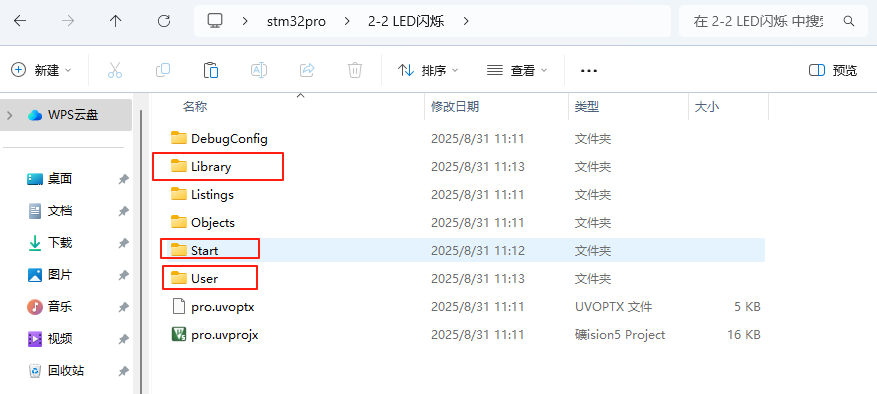
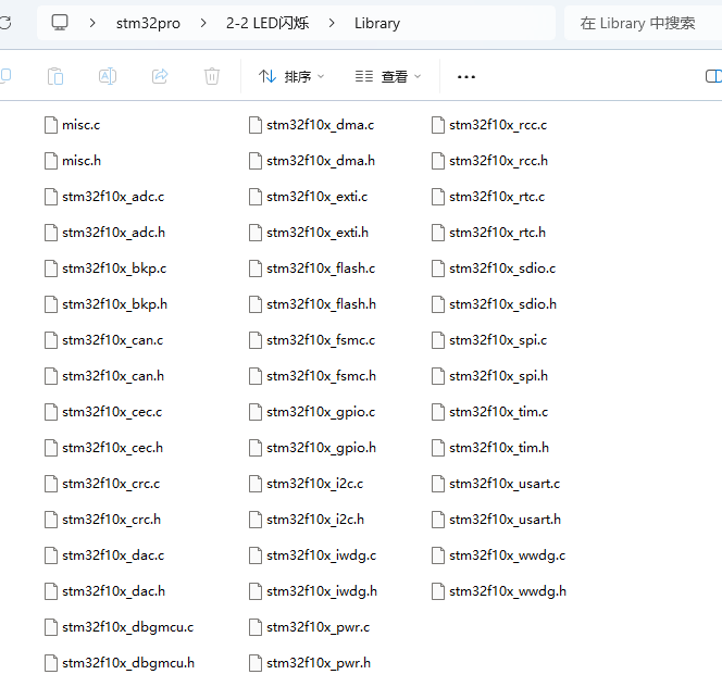
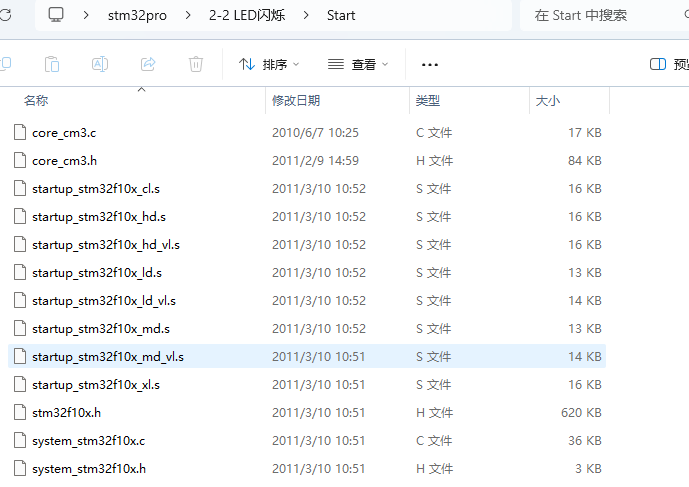
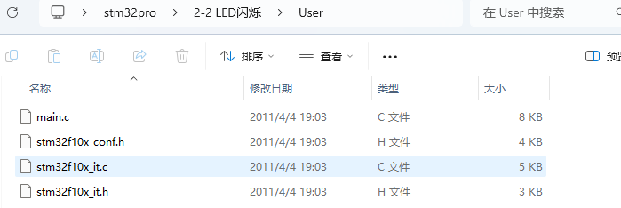
工程模板
新建三个文件夹
点击
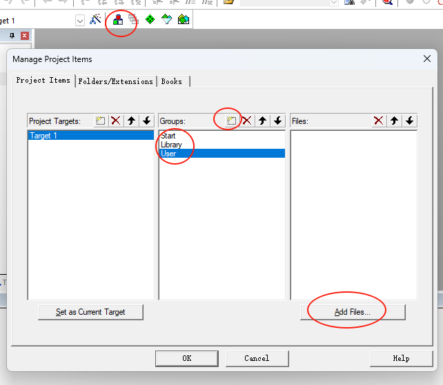
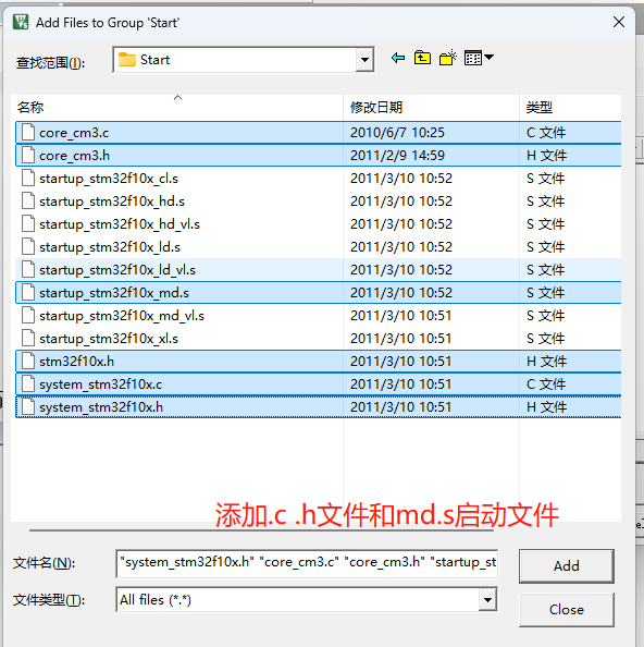
其他两个文件全部添加
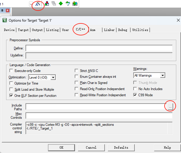
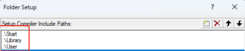
添加三个文件路径
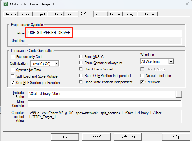
添加DEfine USE_STDPERIPH_DRIVER
使用该exe可以删除一些中间文件

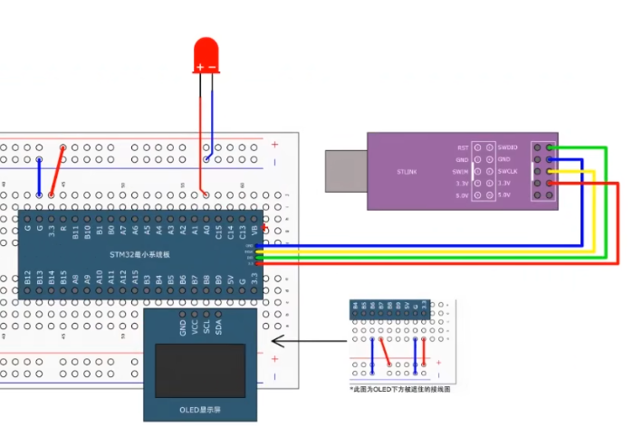
3-1LED闪烁
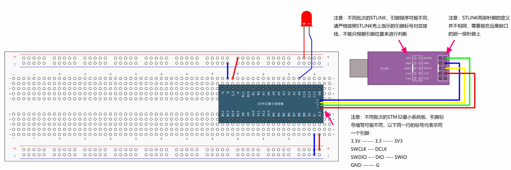
接线图(led长脚接正极)
代码
#include "stm32f10x.h"                  // Device header
#include "Delay.h"
int main(void)
{
	RCC_APB2PeriphClockCmd(RCC_APB2Periph_GPIOA,ENABLE);
	GPIO_InitTypeDef GPIO_InitStructure;
	GPIO_InitStructure.GPIO_Mode=GPIO_Mode_Out_PP; //推挽模式
	GPIO_InitStructure.GPIO_Pin=GPIO_Pin_0;
	GPIO_InitStructure.GPIO_Speed=GPIO_Speed_50MHz;
	GPIO_Init(GPIOA,&GPIO_InitStructure);


	GPIO_WriteBit(GPIOA,GPIO_Pin_0,Bit_RESET);//点亮
	while(1)
	{
		//LED闪烁
		//方法一
		//GPIO_ResetBits(GPIOA,GPIO_Pin_0);//输出低电平
		//Delay_ms(100);
		//GPIO_SetBits(GPIOA,GPIO_Pin_0);//输出高电平
		//Delay_ms(100);

		//方法二
		GPIO_WriteBit(GPIOA,GPIO_Pin_0,Bit_RESET);
		Delay_ms(500);
		GPIO_WriteBit(GPIOA,GPIO_Pin_0,Bit_SET);//熄灭
		Delay_ms(500);

		//方法三(BitAction)强制转换
		//(BitAction) 用于将数值转换为 BitAction 类型,确保参数类型匹配。0 转换为 BIT_RESET,1 转换为 BIT_SET。
		//GPIO_WriteBit(GPIOA,GPIO_Pin_0,(BitAction)0);
		//Delay_ms(500);
		//GPIO_WriteBit(GPIOA,GPIO_Pin_0,(BitAction)1);//熄灭
		//Delay_ms(500);
	}

}
3-2LED流水
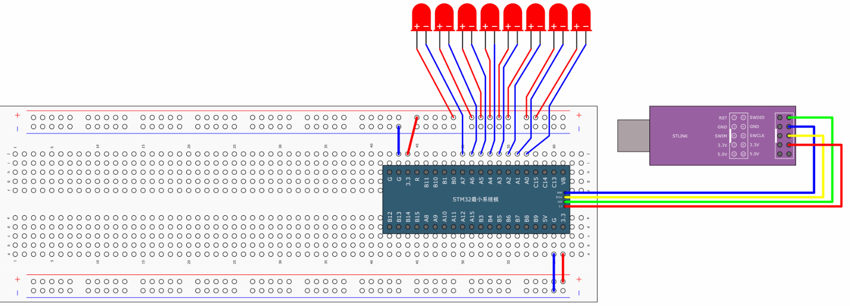
接线图
代码
#include "stm32f10x.h"                  // Device header
#include "Delay.h"
int main(void)
{
	RCC_APB2PeriphClockCmd(RCC_APB2Periph_GPIOA,ENABLE);
	GPIO_InitTypeDef GPIO_InitStructure;
	GPIO_InitStructure.GPIO_Mode=GPIO_Mode_Out_PP; //推挽模式
	GPIO_InitStructure.GPIO_Pin=GPIO_Pin_0;
	GPIO_InitStructure.GPIO_Speed=GPIO_Speed_50MHz;
	GPIO_Init(GPIOA,&GPIO_InitStructure);

	GPIO_WriteBit(GPIOA,GPIO_Pin_0,Bit_RESET);//点亮
	while(1)
	{
		//低电平亮,所以要加上~取反
		GPIO_Write(GPIOA,~0x0001);// 0000 0000 0000 0001
		Delay_ms(500);
		GPIO_Write(GPIOA,~0x0002);// 0000 0000 0000 0010
		Delay_ms(500);
		GPIO_Write(GPIOA,~0x0004);// 0000 0000 0000 0100
		Delay_ms(500);
		GPIO_Write(GPIOA,~0x0008);// 0000 0000 0000 1000
		Delay_ms(500);
		GPIO_Write(GPIOA,~0x0010);// 0000 0000 0001 0000
		Delay_ms(500);
		GPIO_Write(GPIOA,~0x0020);// 0000 0000 0010 0000
		Delay_ms(500);
		GPIO_Write(GPIOA,~0x0040);// 0000 0000 0100 0000
		Delay_ms(500);
		GPIO_Write(GPIOA,~0x0080);// 0000 0000 1000 0000
		Delay_ms(500);
	}

}
3-3蜂鸣器
接线图
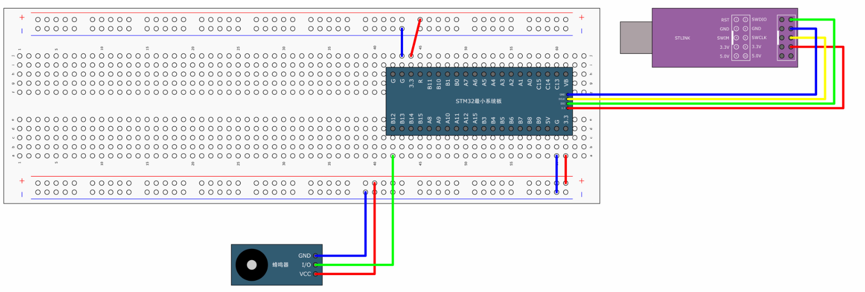
代码
#include "stm32f10x.h"                  // Device header
#include "Delay.h"
int main(void)
{
	RCC_APB2PeriphClockCmd(RCC_APB2Periph_GPIOB,ENABLE);
	GPIO_InitTypeDef GPIO_InitStructure;
	GPIO_InitStructure.GPIO_Mode=GPIO_Mode_Out_PP; //推挽模式
	GPIO_InitStructure.GPIO_Pin=GPIO_Pin_12;
	GPIO_InitStructure.GPIO_Speed=GPIO_Speed_50MHz;
	GPIO_Init(GPIOB,&GPIO_InitStructure);


	while(1)
	{
		//LED闪烁
		//方法一
		GPIO_ResetBits(GPIOB,GPIO_Pin_12);//输出低电平
		Delay_ms(100);
		GPIO_SetBits(GPIOB,GPIO_Pin_12);//输出高电平
		Delay_ms(100);
		GPIO_ResetBits(GPIOB,GPIO_Pin_12);//输出低电平
		Delay_ms(100);
		GPIO_SetBits(GPIOB,GPIO_Pin_12);//输出高电平
		Delay_ms(700);

	}

}
3-4按键控制
模块化设计
创建Hardware文件夹,放.c .h文件
例子LED.c
#include "stm32f10x.h"                  // Device header
/**
  * 函    数:LED初始化
  * 参    数:无
  * 返 回 值:无
  */
void LED_Init(void)
{
	/*开启时钟*/
	RCC_APB2PeriphClockCmd(RCC_APB2Periph_GPIOA, ENABLE);		//开启GPIOA的时钟

	/*GPIO初始化*/
	GPIO_InitTypeDef GPIO_InitStructure;
	GPIO_InitStructure.GPIO_Mode = GPIO_Mode_Out_PP;
	GPIO_InitStructure.GPIO_Pin = GPIO_Pin_1 | GPIO_Pin_2;
	GPIO_InitStructure.GPIO_Speed = GPIO_Speed_50MHz;
	GPIO_Init(GPIOA, &GPIO_InitStructure);						//将PA1和PA2引脚初始化为推挽输出

	/*设置GPIO初始化后的默认电平*/
	GPIO_SetBits(GPIOA, GPIO_Pin_1 | GPIO_Pin_2);				//设置PA1和PA2引脚为高电平
}

/**
  * 函    数:LED1开启
  * 参    数:无
  * 返 回 值:无
  */
void LED1_ON(void)
{
	GPIO_ResetBits(GPIOA, GPIO_Pin_1);		//设置PA1引脚为低电平
}

/**
  * 函    数:LED1关闭
  * 参    数:无
  * 返 回 值:无
  */
void LED1_OFF(void)
{
	GPIO_SetBits(GPIOA, GPIO_Pin_1);		//设置PA1引脚为高电平
}

/**
  * 函    数:LED1状态翻转
  * 参    数:无
  * 返 回 值:无
  */
void LED1_Turn(void)
{
	if (GPIO_ReadOutputDataBit(GPIOA, GPIO_Pin_1) == 0)		//获取输出寄存器的状态,如果当前引脚输出低电平
	{
		GPIO_SetBits(GPIOA, GPIO_Pin_1);					//则设置PA1引脚为高电平
	}
	else													//否则,即当前引脚输出高电平
	{
		GPIO_ResetBits(GPIOA, GPIO_Pin_1);					//则设置PA1引脚为低电平
	}
}

/**
  * 函    数:LED2开启
  * 参    数:无
  * 返 回 值:无
  */
void LED2_ON(void)
{
	GPIO_ResetBits(GPIOA, GPIO_Pin_2);		//设置PA2引脚为低电平
}

/**
  * 函    数:LED2关闭
  * 参    数:无
  * 返 回 值:无
  */
void LED2_OFF(void)
{
	GPIO_SetBits(GPIOA, GPIO_Pin_2);		//设置PA2引脚为高电平
}

/**
  * 函    数:LED2状态翻转
  * 参    数:无
  * 返 回 值:无
  */
void LED2_Turn(void)
{
	if (GPIO_ReadOutputDataBit(GPIOA, GPIO_Pin_2) == 0)		//获取输出寄存器的状态,如果当前引脚输出低电平
	{
		GPIO_SetBits(GPIOA, GPIO_Pin_2);               		//则设置PA2引脚为高电平
	}
	else                                               		//否则,即当前引脚输出高电平
	{
		GPIO_ResetBits(GPIOA, GPIO_Pin_2);             		//则设置PA2引脚为低电平
	}
}
LED.h
#ifndef __LED_H
#define __LED_H

void LED_Init(void);
void LED1_ON(void);
void LED1_OFF(void);
void LED1_Turn(void);
void LED2_ON(void);
void LED2_OFF(void);
void LED2_Turn(void);

#endif
KEY.c
#include "stm32f10x.h"                  // Device header
#include "Delay.h"

/**
  * 函    数:按键初始化
  * 参    数:无
  * 返 回 值:无
  */
void Key_Init(void)
{
	/*开启时钟*/
	RCC_APB2PeriphClockCmd(RCC_APB2Periph_GPIOB, ENABLE);		//开启GPIOB的时钟

	/*GPIO初始化*/
	GPIO_InitTypeDef GPIO_InitStructure;
	GPIO_InitStructure.GPIO_Mode = GPIO_Mode_IPU;
	GPIO_InitStructure.GPIO_Pin = GPIO_Pin_1 | GPIO_Pin_11;
	GPIO_InitStructure.GPIO_Speed = GPIO_Speed_50MHz;
	GPIO_Init(GPIOB, &GPIO_InitStructure);						//将PB1和PB11引脚初始化为上拉输入
}

/**
  * 函    数:按键获取键码
  * 参    数:无
  * 返 回 值:按下按键的键码值,范围:0~2,返回0代表没有按键按下
  * 注意事项:此函数是阻塞式操作,当按键按住不放时,函数会卡住,直到按键松手
  */
uint8_t Key_GetNum(void)
{
	uint8_t KeyNum = 0;		//定义变量,默认键码值为0

	if (GPIO_ReadInputDataBit(GPIOB, GPIO_Pin_1) == 0)			//读PB1输入寄存器的状态,如果为0,则代表按键1按下
	{
		Delay_ms(20);											//延时消抖
		while (GPIO_ReadInputDataBit(GPIOB, GPIO_Pin_1) == 0);	//等待按键松手
		Delay_ms(20);											//延时消抖
		KeyNum = 1;												//置键码为1
	}

	if (GPIO_ReadInputDataBit(GPIOB, GPIO_Pin_11) == 0)			//读PB11输入寄存器的状态,如果为0,则代表按键2按下
	{
		Delay_ms(20);											//延时消抖
		while (GPIO_ReadInputDataBit(GPIOB, GPIO_Pin_11) == 0);	//等待按键松手
		Delay_ms(20);											//延时消抖
		KeyNum = 2;												//置键码为2
	}

	return KeyNum;			//返回键码值,如果没有按键按下,所有if都不成立,则键码为默认值0
}
KEY.h
#ifndef __KEY_H
#define __KEY_H

void Key_Init(void);
uint8_t Key_GetNum(void);

#endif
按键控制代码
#include "stm32f10x.h"                  // Device header
#include "Delay.h"
#include "Key.h"
#include "LED.h"

uint8_t KeyNum;
int main(void)
{
	LED_Init();
	Key_Init();
	while(1)
	{
	 KeyNum = Key_GetNum();
		if(KeyNum ==1)
		{
		LED1_Turn();
		}
		if(KeyNum ==2)
		{
			LED2_Turn();
		}

	}

}
4-1OLED显示屏
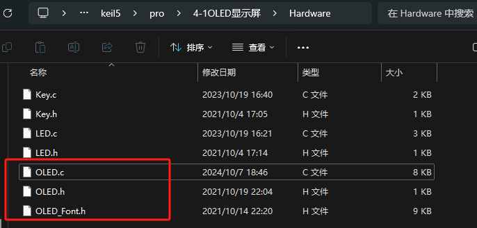
OLED.c
#include "stm32f10x.h"
#include "OLED_Font.h"

/*引脚配置*/
#define OLED_W_SCL(x)		GPIO_WriteBit(GPIOB, GPIO_Pin_8, (BitAction)(x))
#define OLED_W_SDA(x)		GPIO_WriteBit(GPIOB, GPIO_Pin_9, (BitAction)(x))

/*引脚初始化*/
void OLED_I2C_Init(void)
{
    RCC_APB2PeriphClockCmd(RCC_APB2Periph_GPIOB, ENABLE);

	GPIO_InitTypeDef GPIO_InitStructure;
 	GPIO_InitStructure.GPIO_Mode = GPIO_Mode_Out_OD;
	GPIO_InitStructure.GPIO_Speed = GPIO_Speed_50MHz;
	GPIO_InitStructure.GPIO_Pin = GPIO_Pin_8;
 	GPIO_Init(GPIOB, &GPIO_InitStructure);
	GPIO_InitStructure.GPIO_Pin = GPIO_Pin_9;
 	GPIO_Init(GPIOB, &GPIO_InitStructure);

	OLED_W_SCL(1);
	OLED_W_SDA(1);
}

/**
  * @brief  I2C开始
  * @param  无
  * @retval 无
  */
void OLED_I2C_Start(void)
{
	OLED_W_SDA(1);
	OLED_W_SCL(1);
	OLED_W_SDA(0);
	OLED_W_SCL(0);
}

/**
  * @brief  I2C停止
  * @param  无
  * @retval 无
  */
void OLED_I2C_Stop(void)
{
	OLED_W_SDA(0);
	OLED_W_SCL(1);
	OLED_W_SDA(1);
}

/**
  * @brief  I2C发送一个字节
  * @param  Byte 要发送的一个字节
  * @retval 无
  */
void OLED_I2C_SendByte(uint8_t Byte)
{
	uint8_t i;
	for (i = 0; i < 8; i++)
	{
		OLED_W_SDA(!!(Byte & (0x80 >> i)));
		OLED_W_SCL(1);
		OLED_W_SCL(0);
	}
	OLED_W_SCL(1);	//额外的一个时钟,不处理应答信号
	OLED_W_SCL(0);
}

/**
  * @brief  OLED写命令
  * @param  Command 要写入的命令
  * @retval 无
  */
void OLED_WriteCommand(uint8_t Command)
{
	OLED_I2C_Start();
	OLED_I2C_SendByte(0x78);		//从机地址
	OLED_I2C_SendByte(0x00);		//写命令
	OLED_I2C_SendByte(Command);
	OLED_I2C_Stop();
}

/**
  * @brief  OLED写数据
  * @param  Data 要写入的数据
  * @retval 无
  */
void OLED_WriteData(uint8_t Data)
{
	OLED_I2C_Start();
	OLED_I2C_SendByte(0x78);		//从机地址
	OLED_I2C_SendByte(0x40);		//写数据
	OLED_I2C_SendByte(Data);
	OLED_I2C_Stop();
}

/**
  * @brief  OLED设置光标位置
  * @param  Y 以左上角为原点,向下方向的坐标,范围:0~7
  * @param  X 以左上角为原点,向右方向的坐标,范围:0~127
  * @retval 无
  */
void OLED_SetCursor(uint8_t Y, uint8_t X)
{
	OLED_WriteCommand(0xB0 | Y);					//设置Y位置
	OLED_WriteCommand(0x10 | ((X & 0xF0) >> 4));	//设置X位置高4位
	OLED_WriteCommand(0x00 | (X & 0x0F));			//设置X位置低4位
}

/**
  * @brief  OLED清屏
  * @param  无
  * @retval 无
  */
void OLED_Clear(void)
{
	uint8_t i, j;
	for (j = 0; j < 8; j++)
	{
		OLED_SetCursor(j, 0);
		for(i = 0; i < 128; i++)
		{
			OLED_WriteData(0x00);
		}
	}
}

/**
  * @brief  OLED显示一个字符
  * @param  Line 行位置,范围:1~4
  * @param  Column 列位置,范围:1~16
  * @param  Char 要显示的一个字符,范围:ASCII可见字符
  * @retval 无
  */
void OLED_ShowChar(uint8_t Line, uint8_t Column, char Char)
{
	uint8_t i;
	OLED_SetCursor((Line - 1) * 2, (Column - 1) * 8);		//设置光标位置在上半部分
	for (i = 0; i < 8; i++)
	{
		OLED_WriteData(OLED_F8x16[Char - ' '][i]);			//显示上半部分内容
	}
	OLED_SetCursor((Line - 1) * 2 + 1, (Column - 1) * 8);	//设置光标位置在下半部分
	for (i = 0; i < 8; i++)
	{
		OLED_WriteData(OLED_F8x16[Char - ' '][i + 8]);		//显示下半部分内容
	}
}

/**
  * @brief  OLED显示字符串
  * @param  Line 起始行位置,范围:1~4
  * @param  Column 起始列位置,范围:1~16
  * @param  String 要显示的字符串,范围:ASCII可见字符
  * @retval 无
  */
void OLED_ShowString(uint8_t Line, uint8_t Column, char *String)
{
	uint8_t i;
	for (i = 0; String[i] != '\0'; i++)
	{
		OLED_ShowChar(Line, Column + i, String[i]);
	}
}

/**
  * @brief  OLED次方函数
  * @retval 返回值等于X的Y次方
  */
uint32_t OLED_Pow(uint32_t X, uint32_t Y)
{
	uint32_t Result = 1;
	while (Y--)
	{
		Result *= X;
	}
	return Result;
}

/**
  * @brief  OLED显示数字(十进制,正数)
  * @param  Line 起始行位置,范围:1~4
  * @param  Column 起始列位置,范围:1~16
  * @param  Number 要显示的数字,范围:0~4294967295
  * @param  Length 要显示数字的长度,范围:1~10
  * @retval 无
  */
void OLED_ShowNum(uint8_t Line, uint8_t Column, uint32_t Number, uint8_t Length)
{
	uint8_t i;
	for (i = 0; i < Length; i++)
	{
		OLED_ShowChar(Line, Column + i, Number / OLED_Pow(10, Length - i - 1) % 10 + '0');
	}
}

/**
  * @brief  OLED显示数字(十进制,带符号数)
  * @param  Line 起始行位置,范围:1~4
  * @param  Column 起始列位置,范围:1~16
  * @param  Number 要显示的数字,范围:-2147483648~2147483647
  * @param  Length 要显示数字的长度,范围:1~10
  * @retval 无
  */
void OLED_ShowSignedNum(uint8_t Line, uint8_t Column, int32_t Number, uint8_t Length)
{
	uint8_t i;
	uint32_t Number1;
	if (Number >= 0)
	{
		OLED_ShowChar(Line, Column, '+');
		Number1 = Number;
	}
	else
	{
		OLED_ShowChar(Line, Column, '-');
		Number1 = -Number;
	}
	for (i = 0; i < Length; i++)
	{
		OLED_ShowChar(Line, Column + i + 1, Number1 / OLED_Pow(10, Length - i - 1) % 10 + '0');
	}
}

/**
  * @brief  OLED显示数字(十六进制,正数)
  * @param  Line 起始行位置,范围:1~4
  * @param  Column 起始列位置,范围:1~16
  * @param  Number 要显示的数字,范围:0~0xFFFFFFFF
  * @param  Length 要显示数字的长度,范围:1~8
  * @retval 无
  */
void OLED_ShowHexNum(uint8_t Line, uint8_t Column, uint32_t Number, uint8_t Length)
{
	uint8_t i, SingleNumber;
	for (i = 0; i < Length; i++)
	{
		SingleNumber = Number / OLED_Pow(16, Length - i - 1) % 16;
		if (SingleNumber < 10)
		{
			OLED_ShowChar(Line, Column + i, SingleNumber + '0');
		}
		else
		{
			OLED_ShowChar(Line, Column + i, SingleNumber - 10 + 'A');
		}
	}
}

/**
  * @brief  OLED显示数字(二进制,正数)
  * @param  Line 起始行位置,范围:1~4
  * @param  Column 起始列位置,范围:1~16
  * @param  Number 要显示的数字,范围:0~1111 1111 1111 1111
  * @param  Length 要显示数字的长度,范围:1~16
  * @retval 无
  */
void OLED_ShowBinNum(uint8_t Line, uint8_t Column, uint32_t Number, uint8_t Length)
{
	uint8_t i;
	for (i = 0; i < Length; i++)
	{
		OLED_ShowChar(Line, Column + i, Number / OLED_Pow(2, Length - i - 1) % 2 + '0');
	}
}

/**
  * @brief  OLED初始化
  * @param  无
  * @retval 无
  */
void OLED_Init(void)
{
	uint32_t i, j;

	for (i = 0; i < 1000; i++)			//上电延时
	{
		for (j = 0; j < 1000; j++);
	}

	OLED_I2C_Init();			//端口初始化

	OLED_WriteCommand(0xAE);	//关闭显示

	OLED_WriteCommand(0xD5);	//设置显示时钟分频比/振荡器频率
	OLED_WriteCommand(0x80);

	OLED_WriteCommand(0xA8);	//设置多路复用率
	OLED_WriteCommand(0x3F);

	OLED_WriteCommand(0xD3);	//设置显示偏移
	OLED_WriteCommand(0x00);

	OLED_WriteCommand(0x40);	//设置显示开始行

	OLED_WriteCommand(0xA1);	//设置左右方向,0xA1正常 0xA0左右反置

	OLED_WriteCommand(0xC8);	//设置上下方向,0xC8正常 0xC0上下反置

	OLED_WriteCommand(0xDA);	//设置COM引脚硬件配置
	OLED_WriteCommand(0x12);

	OLED_WriteCommand(0x81);	//设置对比度控制
	OLED_WriteCommand(0xCF);

	OLED_WriteCommand(0xD9);	//设置预充电周期
	OLED_WriteCommand(0xF1);

	OLED_WriteCommand(0xDB);	//设置VCOMH取消选择级别
	OLED_WriteCommand(0x30);

	OLED_WriteCommand(0xA4);	//设置整个显示打开/关闭

	OLED_WriteCommand(0xA6);	//设置正常/倒转显示

	OLED_WriteCommand(0x8D);	//设置充电泵
	OLED_WriteCommand(0x14);

	OLED_WriteCommand(0xAF);	//开启显示

	OLED_Clear();				//OLED清屏
}
OLED.h
#ifndef __OLED_H
#define __OLED_H

void OLED_Init(void);
void OLED_Clear(void);
void OLED_ShowChar(uint8_t Line, uint8_t Column, char Char);
void OLED_ShowString(uint8_t Line, uint8_t Column, char *String);
void OLED_ShowNum(uint8_t Line, uint8_t Column, uint32_t Number, uint8_t Length);
void OLED_ShowSignedNum(uint8_t Line, uint8_t Column, int32_t Number, uint8_t Length);
void OLED_ShowHexNum(uint8_t Line, uint8_t Column, uint32_t Number, uint8_t Length);
void OLED_ShowBinNum(uint8_t Line, uint8_t Column, uint32_t Number, uint8_t Length);

#endif
OLED_Font.h
#ifndef __OLED_FONT_H
#define __OLED_FONT_H

/*OLED字模库,宽8像素,高16像素*/
const uint8_t OLED_F8x16[][16]=
{
	0x00,0x00,0x00,0x00,0x00,0x00,0x00,0x00,
	0x00,0x00,0x00,0x00,0x00,0x00,0x00,0x00,//  0

	0x00,0x00,0x00,0xF8,0x00,0x00,0x00,0x00,
	0x00,0x00,0x00,0x33,0x30,0x00,0x00,0x00,//! 1

	0x00,0x10,0x0C,0x06,0x10,0x0C,0x06,0x00,
	0x00,0x00,0x00,0x00,0x00,0x00,0x00,0x00,//" 2

	0x40,0xC0,0x78,0x40,0xC0,0x78,0x40,0x00,
	0x04,0x3F,0x04,0x04,0x3F,0x04,0x04,0x00,//# 3

	0x00,0x70,0x88,0xFC,0x08,0x30,0x00,0x00,
	0x00,0x18,0x20,0xFF,0x21,0x1E,0x00,0x00,//$ 4

	0xF0,0x08,0xF0,0x00,0xE0,0x18,0x00,0x00,
	0x00,0x21,0x1C,0x03,0x1E,0x21,0x1E,0x00,//% 5

	0x00,0xF0,0x08,0x88,0x70,0x00,0x00,0x00,
	0x1E,0x21,0x23,0x24,0x19,0x27,0x21,0x10,//& 6
			.
			.
			.
			.
	0x00,0x06,0x01,0x01,0x02,0x02,0x04,0x04,
	0x00,0x00,0x00,0x00,0x00,0x00,0x00,0x00,//~ 94
};

#endif
mian.c
#include "stm32f10x.h"                  // Device header
#include "Delay.h"
#include "OLED.h"

int main(void){

	OLED_Init();//初始化
	OLED_ShowChar(1,1,'A');//第一行第一列输出字符A
	OLED_ShowString(1,3,"CHENJIAWEI");//第一行第三列打印字符串
	OLED_ShowSignedNum(3,1,-66,2);//第三行弟1列打印一个有符号的整数-66
	OLED_ShowBinNum(2,1,0xAA55,16); //二进制显示1010101001010101
	OLED_ShowHexNum(3,1,0xAA55,4);//十六进制形式显示AA55

	while(1)
	{

	}
}
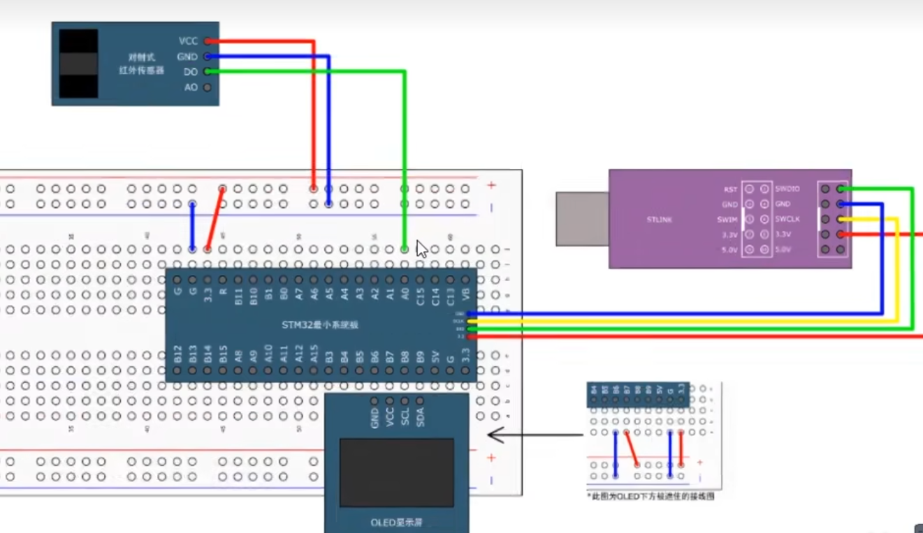
5-1对射式红外传感器计次
EXTI(外部中断)基本结构
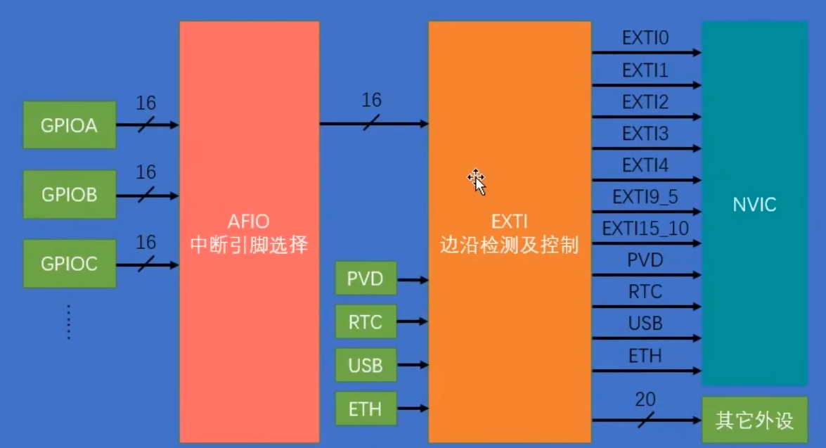
配置四个
第一步,配置RCC,把我们这里涉及的外设的时钟都打开
第二步,配置GPIO选择我们的端口为输入模式
第三步,配置AFIO。选择我们用的这一路GPI,连接到后面的EXTI
第四步,配置EXTI,选择边沿触发方式,比如上升沿、下降沿或者双边沿,还有选择触发响应方式,可以选择中断响应和事件响应,一般选择终端响应
第五步,配置NVIC,给我们这个中断选择一个合适的优洗级,最后,通过NVIC,外部中断信号就能进入CPU了
CountSensor.c
#include "stm32f10x.h"                  // Device header


uint16_t CountSensor_Count;

void CountSensor_Init(void){

	RCC_APB2PeriphClockCmd(RCC_APB2Periph_GPIOB,ENABLE);
	RCC_APB2PeriphClockCmd(RCC_APB2Periph_AFIO,ENABLE);

	//配置GPIO
	GPIO_InitTypeDef GPIO_InitStructure;
	GPIO_InitStructure.GPIO_Mode=GPIO_Mode_IPU;
	GPIO_InitStructure.GPIO_Pin=GPIO_Pin_14;
	GPIO_InitStructure.GPIO_Speed=GPIO_Speed_50MHz;
	GPIO_Init(GPIOB, &GPIO_InitStructure);

	//用于 配置外部中断(EXTI)的 GPIO 引脚映射
	GPIO_EXTILineConfig(GPIO_PortSourceGPIOB,GPIO_PinSource14);

	//第四步配置EXTI
	EXTI_InitTypeDef EXTI_InitStructure;
	EXTI_InitStructure.EXTI_Line=EXTI_Line14;
	EXTI_InitStructure.EXTI_LineCmd=ENABLE;
	EXTI_InitStructure.EXTI_Mode=EXTI_Mode_Interrupt;
	EXTI_InitStructure.EXTI_Trigger=EXTI_Trigger_Rising_Falling;//可以选择上升沿或者下降沿,或者上升下降
	//(EXTI_Trigger_Rising = 0x08,
    // EXTI_Trigger_Falling = 0x0C,
    //EXTI_Trigger_Rising_Falling = 0x10)

	EXTI_Init(&EXTI_InitStructure);

	//第五步配置NVIC
	NVIC_PriorityGroupConfig(NVIC_PriorityGroup_2);//选择两位抢占两位响应,比较平均

	NVIC_InitTypeDef NVIC_InitStructure;
	NVIC_InitStructure.NVIC_IRQChannel=EXTI15_10_IRQn;
	NVIC_InitStructure.NVIC_IRQChannelCmd=ENABLE;
	NVIC_InitStructure.NVIC_IRQChannelPreemptionPriority=1;//抢占优先级
	NVIC_InitStructure.NVIC_IRQChannelSubPriority=1;//响应优先级
	NVIC_Init(&NVIC_InitStructure);
}
uint16_t CountSensor_Get(void)
{
	return CountSensor_Count;
}

void EXTI15_10_IRQHandler(void) //中断函数起动文件
{
	if(EXTI_GetITStatus(EXTI_Line14)== SET)
	{
	CountSensor_Count++;
	EXTI_ClearITPendingBit(EXTI_Line14);
	}
}
CountSensor.h
#ifndef __COUNT_SENSOR_H
#define __COUNT_SENSOR_H

void CountSensor_Init(void);
uint16_t CountSensor_Get(void);
#endif
main.c
#include "stm32f10x.h"                  // Device header
#include "Delay.h"
#include "OLED.h"
#include "CountSensor.h"
int main(void){
	OLED_Init();
	CountSensor_Init();


	OLED_ShowString(1,1,"Count:");

	while(1)
	{
		OLED_ShowNum(1,7,CountSensor_Get(),5);
	}
}
6-1定时器定时中断
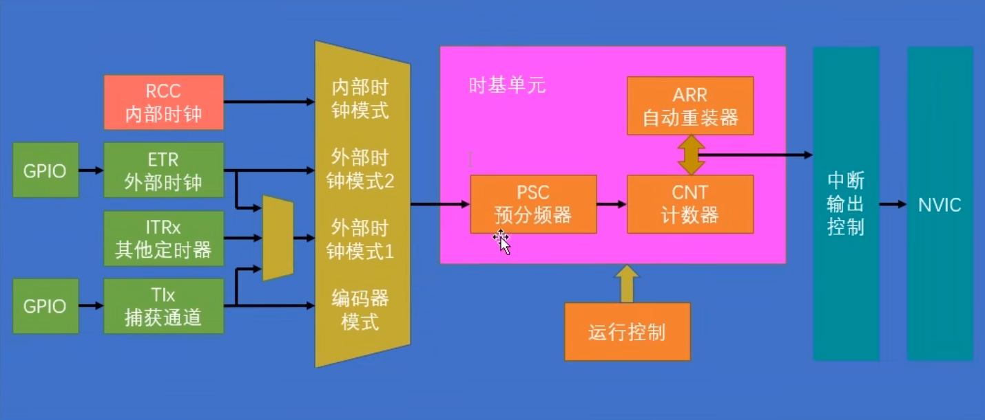
第一步,R©C开启时钟,这个基本上每个代码都是第一步
第三步,选择时基单元的时钟源,对手定时中断。我们就选择内部时钟源
第三步。配置时基弹元,包括这里的预分频器,自动重装器,计数模式等等(使用结构体)
第四步,配置输出中断控制,允许更新中断输出到NVIC
第五步,配置NVIC,在NVM©中打研定时器中断的通道,并分配一个优先级
第六步,就是运行控制了,整个模块配置完成后,我们还需要使能-下计数器
主要函数
void TIM_DeInit(TIM_TypeDef* TIMx);
void TIM_TimeBaseInit(TIM_TypeDef* TIMx, TIM_TimeBaseInitTypeDef* TIM_TimeBaseInitStruct);
计数器溢出频率:CK_CNT_OV=CK_CNT/(ARR+1)=CK_PSC/(PSC+1)/(ARR+1)
main.c
#include "stm32f10x.h"                  // Device header
#include "Delay.h"
#include "OLED.h"
#include "Timer.h"

uint16_t Num;
int main(void){

	OLED_Init();
	Timer_Init();

	OLED_ShowString(1,1,"Num:");
	while(1)
	{
	OLED_ShowNum(1,5,Num,5);
		OLED_ShowNum(2,5,TIM_GetCounter(TIM2),5);
	}
}

void TIM2_IRQHandler(void)
{

	if (TIM_GetITStatus(TIM2,TIM_IT_Update)==SET)
		{
				Num++;
				TIM_ClearITPendingBit(TIM2,TIM_IT_Update);
		}
}
Timer.c
#include "stm32f10x.h"                  // Device header

void Timer_Init(void)
{
	RCC_APB1PeriphClockCmd(RCC_APB1Periph_TIM2,ENABLE);

	TIM_InternalClockConfig(TIM2);

	TIM_TimeBaseInitTypeDef TIM_TimeBaseInitStructure;
	TIM_TimeBaseInitStructure.TIM_ClockDivision=TIM_CKD_DIV1;
	TIM_TimeBaseInitStructure.TIM_CounterMode=TIM_CounterMode_Up;
	TIM_TimeBaseInitStructure.TIM_Period=10000-1; //自动重装载值 规定10000就是一秒,如果1000就是0.1秒就加一
	TIM_TimeBaseInitStructure.TIM_Prescaler=7200-1; // 预分频值
	TIM_TimeBaseInitStructure.TIM_RepetitionCounter=0;
	TIM_TimeBaseInit(TIM2,&TIM_TimeBaseInitStructure);

	TIM_ClearFlag(TIM2,TIM_FLAG_Update);
	TIM_ITConfig(TIM2,TIM_IT_Update,ENABLE);

	//NVIC
	NVIC_PriorityGroupConfig(NVIC_PriorityGroup_2);

	NVIC_InitTypeDef NVIC_InitStructure;
	NVIC_InitStructure.NVIC_IRQChannel=TIM2_IRQn;
	NVIC_InitStructure.NVIC_IRQChannelCmd=ENABLE;
	NVIC_InitStructure.NVIC_IRQChannelPreemptionPriority=2;
	NVIC_InitStructure.NVIC_IRQChannelSubPriority=1;
	NVIC_Init(&NVIC_InitStructure);

	TIM_Cmd(TIM2,ENABLE);
}

//定时中断启动函数,作为模板复制到main函数中使用
//void TIM2_IRQHandler(void)
//{

//if (TIM_GetITStatus(TIM2,TIM_IT_Update)==SET)
//{
//	TIM_ClearITPendingBit(TIM2,TIM_IT_Update);
//}
//}
Timer.h
#ifndef __TIMER_H
#define __TIMER_H

void Timer_Init(void);
void TIM2_IRQHandler(void);
#endif
6-2定时器外部中断
通过 TIM2 的 ETR 模式 实现了外部脉冲计数,每 10 个上升沿 触发一次中断,Num 加 1。
关键配置:
TIM_ETRClockMode2Config:外部时钟模式。
TIM_Period = 9:10 个脉冲溢出一次。
TIM_ITConfig:使能更新中断。
Timer.c
#include "stm32f10x.h"                  // Device header

void Timer_Init(void)
{
	RCC_APB1PeriphClockCmd(RCC_APB1Periph_TIM2,ENABLE);

	RCC_APB2PeriphClockCmd(RCC_APB2Periph_GPIOA,ENABLE);
	GPIO_InitTypeDef GPIO_InitStructure;
	GPIO_InitStructure.GPIO_Mode=GPIO_Mode_IPU;
	GPIO_InitStructure.GPIO_Pin=GPIO_Pin_0;
	GPIO_InitStructure.GPIO_Speed=GPIO_Speed_50MHz;

	GPIO_Init(GPIOA,&GPIO_InitStructure);

	//定时器配置为外部时钟模式
	TIM_ETRClockMode2Config(TIM2,TIM_ExtTRGPSC_OFF,TIM_ExtTRGPolarity_NonInverted,0x00);
	//将 TIM2 的时钟源配置为 外部触发(ETR)模式,即 PA0 引脚(TIM2_ETR) 的上升沿作为计数时钟。
	//TIM_ExtTRGPSC_OFF:不使用预分频(每个上升沿直接计数)。
	//TIM_ExtTRGPolarity_NonInverted:上升沿触发。

	TIM_TimeBaseInitTypeDef TIM_TimeBaseInitStructure;
	TIM_TimeBaseInitStructure.TIM_ClockDivision=TIM_CKD_DIV1;
	TIM_TimeBaseInitStructure.TIM_CounterMode=TIM_CounterMode_Up;
	TIM_TimeBaseInitStructure.TIM_Period=10-1; //计数器从 0 开始,计数到 9 时溢出(共 10 个脉冲)
	TIM_TimeBaseInitStructure.TIM_Prescaler=1-1; // 预分频值
	TIM_TimeBaseInitStructure.TIM_RepetitionCounter=0;
	TIM_TimeBaseInit(TIM2,&TIM_TimeBaseInitStructure);

	TIM_ClearFlag(TIM2,TIM_FLAG_Update);
	TIM_ITConfig(TIM2,TIM_IT_Update,ENABLE);//使能 更新中断,当计数器溢出(从 9 回到 0)时触发中断,在 TIM2_IRQHandler 中执行 Num++。

	//NVIC
	NVIC_PriorityGroupConfig(NVIC_PriorityGroup_2);

	NVIC_InitTypeDef NVIC_InitStructure;
	NVIC_InitStructure.NVIC_IRQChannel=TIM2_IRQn;
	NVIC_InitStructure.NVIC_IRQChannelCmd=ENABLE;
	NVIC_InitStructure.NVIC_IRQChannelPreemptionPriority=2;
	NVIC_InitStructure.NVIC_IRQChannelSubPriority=1;
	NVIC_Init(&NVIC_InitStructure);

	TIM_Cmd(TIM2,ENABLE);
}

uint16_t Timer_GetCounter(void)
{
	return TIM_GetCounter(TIM2);

}
//定时中断启动函数,作为模板复制到main函数中使用
//void TIM2_IRQHandler(void)
//{

//if (TIM_GetITStatus(TIM2,TIM_IT_Update)==SET)
//{
//	TIM_ClearITPendingBit(TIM2,TIM_IT_Update);
//}
//}
main.c
#include "stm32f10x.h"                  // Device header
#include "Delay.h"
#include "OLED.h"
#include "Timer.h"

uint16_t Num;
int main(void){

	OLED_Init();
	Timer_Init();

	OLED_ShowString(1,1,"Num:");
	OLED_ShowString(2,1,"CNT:");
	while(1)
	{
	OLED_ShowNum(1,5,Num,5);
		OLED_ShowNum(2,5,Timer_GetCounter(),5);
		//OLED_ShowNum(2,5,TIM_GetCounter(TIM2),5);
	}
}

void TIM2_IRQHandler(void)
{

	if (TIM_GetITStatus(TIM2,TIM_IT_Update)==SET)
		{
				Num++;
				TIM_ClearITPendingBit(TIM2,TIM_IT_Update);
		}
}
6-3 PWM点亮LED呼吸灯
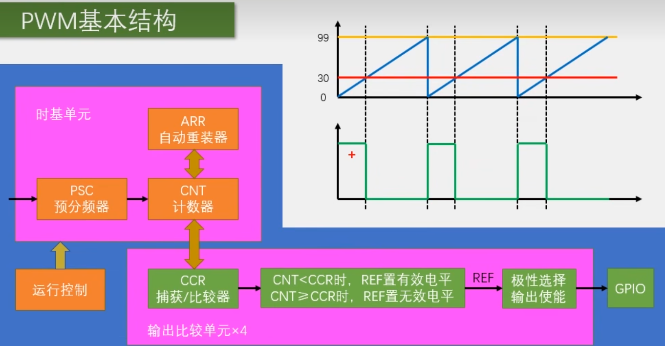
第一步,RCC开启时钟,把我们要用的TIM外设和GPIO外设的时钟打开
第三步,配置时基单元,包括这前面的时钟源选择
第三步,配置输出比较单晁
第四步,配置GPIO,把PWM对应的GPIO口,初始化为复用推挽输出的配置
重要函数:
| 函数 | 说明 |
|---|---|
| GPIO_Init() | 配置 PWM 引脚 |
| TIM_TimeBaseInit() | 设置 PWM 频率和分辨率 |
| TIM_OCxInit() | 启用 PWM 输出 |
| TIM_SetComparex() | 占空比调节,动态调整亮度 |
main.c
#include "stm32f10x.h"                  // Device header
#include "Delay.h"
#include "OLED.h"
#include "PWM.h"

uint8_t i;
int main(void){

	OLED_Init();
	PWM_Init();

	while(1)
	{
		for(i=0;i<=100;i++)
		{
			PWM_SetCompare1(i);
			Delay_ms(20);
			OLED_ShowNum(1,1,i,4);
		}
		for(i=0;i<=100;i++)
		{
			PWM_SetCompare1(100-i);
			OLED_ShowNum(1,1,100-i,4);
			Delay_ms(20);
		}
	}
}
PWM.h
#ifndef __PWM_H
#define __PWM_H
void PWM_Init(void);
void PWM_SetCompare1(uint16_t Compare);
#endif
PWM.c
#include "stm32f10x.h"                  // Device header

void PWM_Init(void)
{
	RCC_APB1PeriphClockCmd(RCC_APB1Periph_TIM2,ENABLE);
	RCC_APB2PeriphClockCmd(RCC_APB2Periph_GPIOA, ENABLE);		//开启GPIOA的时钟

	/*GPIO初始化*/
	GPIO_InitTypeDef GPIO_InitStructure;
	GPIO_InitStructure.GPIO_Mode = GPIO_Mode_AF_PP;
	GPIO_InitStructure.GPIO_Pin = GPIO_Pin_0;
	GPIO_InitStructure.GPIO_Speed = GPIO_Speed_50MHz;
	GPIO_Init(GPIOA, &GPIO_InitStructure);

	//配置 TIM2 定时器使用内部时钟源
	TIM_InternalClockConfig(TIM2);

	TIM_TimeBaseInitTypeDef TIM_TimeBaseInitStructure;
	TIM_TimeBaseInitStructure.TIM_ClockDivision=TIM_CKD_DIV1;
	TIM_TimeBaseInitStructure.TIM_CounterMode=TIM_CounterMode_Up;
	TIM_TimeBaseInitStructure.TIM_Period=100-1; //ARR
	TIM_TimeBaseInitStructure.TIM_Prescaler=720-1; //PSC
	TIM_TimeBaseInitStructure.TIM_RepetitionCounter=0;
	TIM_TimeBaseInit(TIM2,&TIM_TimeBaseInitStructure);

	TIM_OCInitTypeDef TIM_OCInitStructure;
	//PWM结构体初始化赋值,再修改其中部分参数
	TIM_OCStructInit(&TIM_OCInitStructure);
	TIM_OCInitStructure.TIM_OCMode=TIM_OCMode_PWM1;
	TIM_OCInitStructure.TIM_OCPolarity=TIM_OCPolarity_High;
	TIM_OCInitStructure.TIM_OutputState=TIM_OutputState_Enable;
	TIM_OCInitStructure.TIM_Pulse=50; //CCR
	TIM_OC1Init(TIM2,&TIM_OCInitStructure);

	// 启动 TIM2 定时器
	TIM_Cmd(TIM2,ENABLE);


}
//设置TIM2定时器通道1的PWM占空比
void PWM_SetCompare1(uint16_t Compare)
{
	TIM_SetCompare1(TIM2,Compare);
}
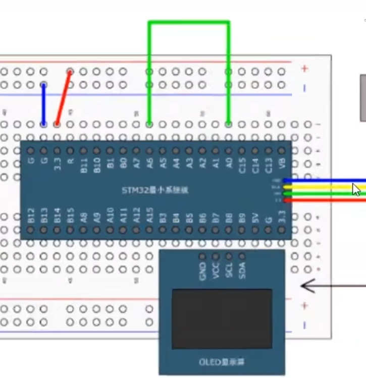
6-4 PWM驱动舵机
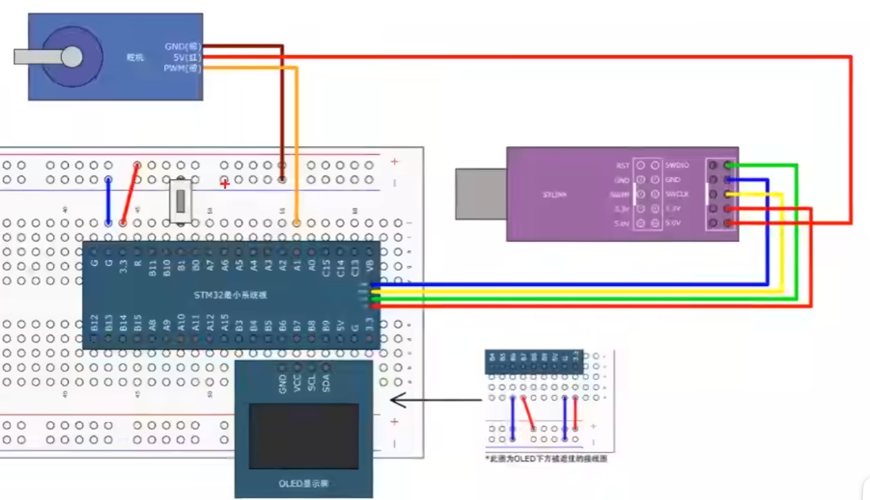
定时器通道 默认 GPIO 引脚(STM32F10x)
TIM2_CH1--->PA0
TIM2_CH2--->PA1
TIM2_CH3--->PA2
TIM2_CH4--->PA3
Servo.c
#include "stm32f10x.h"                  // Device header
#include "PWM.h"

void Servo_Init(void)
{
	PWM_Init();


}

// 0--> 500
// 180度-->2500
void Servo_SetAngle(float Angle)
{

	PWM_SetCompare2(Angle /180*2000+500);
}
Servo.h
#ifndef __SERVO_h
#define __SERVO_H

void Servo_Init(void);
void Servo_SetAngle(float Angle);

#endif
PWM.c
#include "stm32f10x.h"                  // Device header

void PWM_Init(void)
{
	RCC_APB1PeriphClockCmd(RCC_APB1Periph_TIM2,ENABLE);
	RCC_APB2PeriphClockCmd(RCC_APB2Periph_GPIOA, ENABLE);		//开启GPIOA的时钟

	/*GPIO初始化*/
	GPIO_InitTypeDef GPIO_InitStructure;
	GPIO_InitStructure.GPIO_Mode = GPIO_Mode_AF_PP;
	GPIO_InitStructure.GPIO_Pin = GPIO_Pin_1;//Pin1对应通道2
	GPIO_InitStructure.GPIO_Speed = GPIO_Speed_50MHz;
	GPIO_Init(GPIOA, &GPIO_InitStructure);

	//配置 TIM2 定时器使用内部时钟源
	TIM_InternalClockConfig(TIM2);

	TIM_TimeBaseInitTypeDef TIM_TimeBaseInitStructure;
	TIM_TimeBaseInitStructure.TIM_ClockDivision=TIM_CKD_DIV1;
	TIM_TimeBaseInitStructure.TIM_CounterMode=TIM_CounterMode_Up;
	TIM_TimeBaseInitStructure.TIM_Period=20000-1; //ARR
	TIM_TimeBaseInitStructure.TIM_Prescaler=72-1; //PSC
	TIM_TimeBaseInitStructure.TIM_RepetitionCounter=0;
	TIM_TimeBaseInit(TIM2,&TIM_TimeBaseInitStructure);

	TIM_OCInitTypeDef TIM_OCInitStructure;
	//PWM结构体初始化赋值,再修改其中部分参数
	TIM_OCStructInit(&TIM_OCInitStructure);
	TIM_OCInitStructure.TIM_OCMode=TIM_OCMode_PWM1;
	TIM_OCInitStructure.TIM_OCPolarity=TIM_OCPolarity_High;
	TIM_OCInitStructure.TIM_OutputState=TIM_OutputState_Enable;
	TIM_OCInitStructure.TIM_Pulse=0; //CCR
	//初始化通道2
	TIM_OC2Init(TIM2,&TIM_OCInitStructure);

	// 启动 TIM2 定时器
	TIM_Cmd(TIM2,ENABLE);


}
//设置TIM2定时器通道1的PWM占空比
void PWM_SetCompare2(uint16_t Compare)
{
	TIM_SetCompare2(TIM2,Compare);
}
PWM.h
#ifndef __PWM_H
#define __PWM_H
void PWM_Init(void);
void PWM_SetCompare2(uint16_t Compare);
#endif
main.c
#include "stm32f10x.h"                  // Device header
#include "Delay.h"
#include "OLED.h"
#include "Servo.h"
#include "Key.h"

uint8_t KeyNum;
float Angle;
int main(void){

	OLED_Init();
	Servo_Init();
	Key_Init();
	Servo_SetAngle(90);

	OLED_ShowString(1,1,"Angle:");
	while(1)
	{
		KeyNum = Key_GetNum();
		if(KeyNum ==1)
		{
			Angle+=30;//每按一次加30°
			if(Angle >180)
			{
				Angle = 0;
			}
		}
		Servo_SetAngle(Angle);
		OLED_ShowNum(1,7,Angle,3);
	}
}
6-5 PWM驱动直流电机
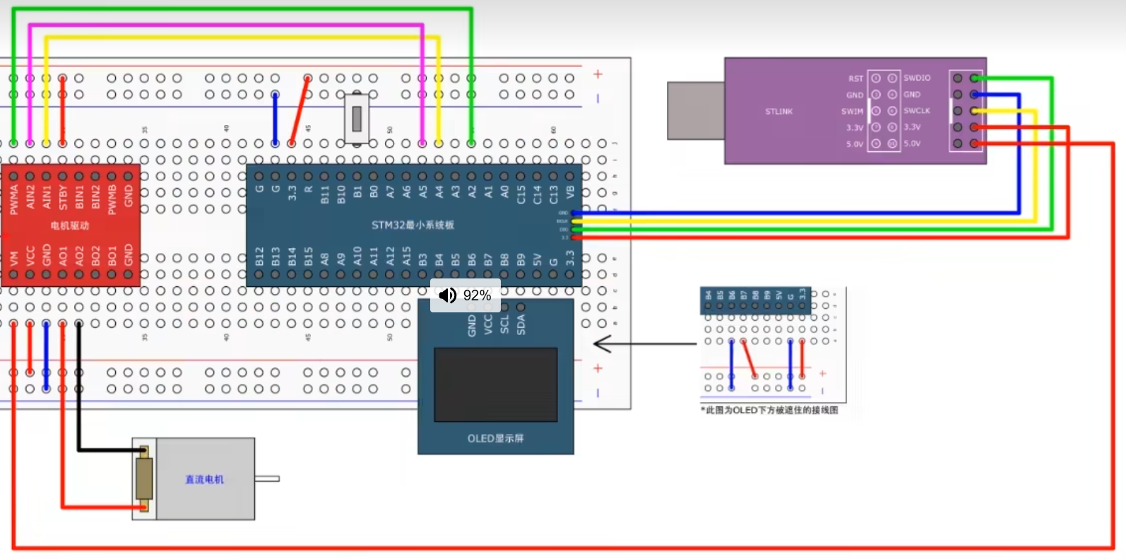
由于利用pwm驱动PA2端口,所以是通道3
Motor.c
#include "stm32f10x.h"                  // Device header
#include "PWM.h"                  // Device header

void Motor_Init(void)
{
	RCC_APB2PeriphClockCmd(RCC_APB2Periph_GPIOA,ENABLE);

	GPIO_InitTypeDef GPIO_InitStructure;
	GPIO_InitStructure.GPIO_Mode=GPIO_Mode_Out_PP;
	GPIO_InitStructure.GPIO_Pin=GPIO_Pin_4 | GPIO_Pin_5;
	GPIO_InitStructure.GPIO_Speed=GPIO_Speed_50MHz;
	GPIO_Init(GPIOA,&GPIO_InitStructure);

	PWM_Init();
}
void Motor_SetSpeed(int8_t Speed)
{
	if(Speed >=0)
	{
		GPIO_SetBits(GPIOA,GPIO_Pin_4);
		GPIO_ResetBits(GPIOA,GPIO_Pin_5);
		PWM_SetCompare3(Speed);
	}
	else{
		GPIO_ResetBits(GPIOA,GPIO_Pin_4);
		GPIO_SetBits(GPIOA,GPIO_Pin_5);
		PWM_SetCompare3(-Speed);
	}

}
Motor.h
#ifndef __MOTOR_H
#define __MOTOR_H

void Motor_Init(void);

void Motor_SetSpeed(int8_t Speed);

#endif
PWM.c
#include "stm32f10x.h" // Device header
void PWM_Init(void)
{
RCC_APB1PeriphClockCmd(RCC_APB1Periph_TIM2,ENABLE);
RCC_APB2PeriphClockCmd(RCC_APB2Periph_GPIOA, ENABLE); //开启GPIOA的时钟
/*GPIO初始化*/
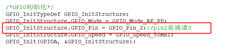
GPIO_InitTypeDef GPIO_InitStructure;
GPIO_InitStructure.GPIO_Mode = GPIO_Mode_AF_PP;
GPIO_InitStructure.GPIO_Pin = GPIO_Pin_2;//pin2是通道3
GPIO_InitStructure.GPIO_Speed = GPIO_Speed_50MHz;
GPIO_Init(GPIOA, &GPIO_InitStructure);
//配置 TIM2 定时器使用内部时钟源
TIM_InternalClockConfig(TIM2);
TIM_TimeBaseInitTypeDef TIM_TimeBaseInitStructure;
TIM_TimeBaseInitStructure.TIM_ClockDivision=TIM_CKD_DIV1;
TIM_TimeBaseInitStructure.TIM_CounterMode=TIM_CounterMode_Up;
TIM_TimeBaseInitStructure.TIM_Period=100-1; //ARR
TIM_TimeBaseInitStructure.TIM_Prescaler=72-1; //PSC
TIM_TimeBaseInitStructure.TIM_RepetitionCounter=0;
TIM_TimeBaseInit(TIM2,&TIM_TimeBaseInitStructure);
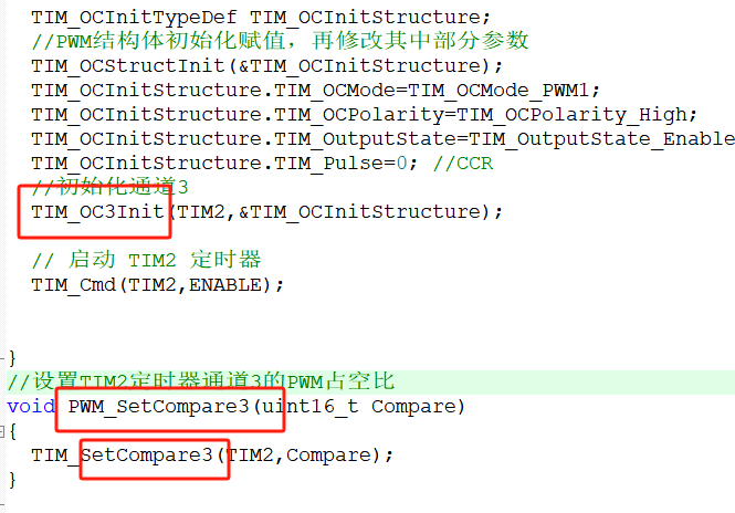
TIM_OCInitTypeDef TIM_OCInitStructure;
//PWM结构体初始化赋值,再修改其中部分参数
TIM_OCStructInit(&TIM_OCInitStructure);
TIM_OCInitStructure.TIM_OCMode=TIM_OCMode_PWM1;
TIM_OCInitStructure.TIM_OCPolarity=TIM_OCPolarity_High;
TIM_OCInitStructure.TIM_OutputState=TIM_OutputState_Enable;
TIM_OCInitStructure.TIM_Pulse=0; //CCR
//初始化通道3
TIM_OC3Init(TIM2,&TIM_OCInitStructure);
// 启动 TIM2 定时器
TIM_Cmd(TIM2,ENABLE);
}
//设置TIM2定时器通道3的PWM占空比
void PWM_SetCompare3(uint16_t Compare)
{
TIM_SetCompare3(TIM2,Compare);
}
PWM.h
#ifndef __PWM_H
#define __PWM_H
void PWM_Init(void);
void PWM_SetCompare3(uint16_t Compare);
#endif
main.c
#include "stm32f10x.h"                  // Device header
#include "Delay.h"
#include "OLED.h"
#include "Motor.h"
#include "Key.h"


uint8_t KeyNum;
int8_t Speed;
//uint8_t KeyNum uint8_t 无符号 8位整数(0 ~ 255)
//int8_t Speed	int8_t	有符号 8位整数(-128 ~ 127)

int main(void){

	OLED_Init();
	Motor_Init();
	Key_Init();
	Motor_SetSpeed(20);
	OLED_ShowString(1,1,"Speed:");
	OLED_ShowString(2,1,"leftButton:=0");//归零
	OLED_ShowString(3,1,"rightButton:+20");
	while(1)
	{
		KeyNum = Key_GetNum();//获取按键值,左边为2,右边为1
		if(KeyNum==1)
		{
			Speed += 20;
			if (Speed>100)
			{
				Speed = -100;
			}
		}
		else
		{
			if(KeyNum==2)
			{
					Speed = 0;
			}
		}
		Motor_SetSpeed(Speed);
		OLED_ShowSignedNum(1,7,Speed,3);
	}
}
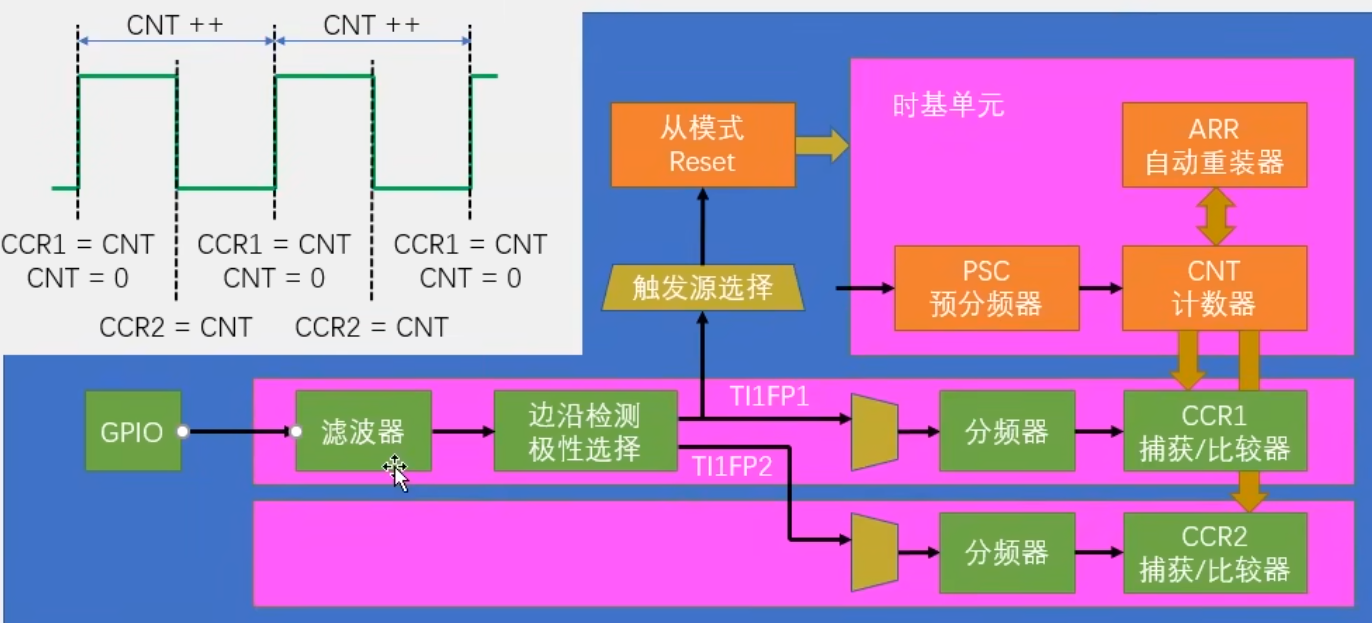
6-6输入捕获模式测频率
第一步,RCC开启时钟,把GPIO和TIM的时钟打开
第二步,GPIO初始化,把GPIO配置成输入模式
第三步,配置时基单元,让CNT计数器在内部时钟的驱动下自增运行
第四步,配置输入捕获单元,用结构体实现(包括滤波器、极性、直连通道还是交叉通道、分频器这些参数)
第五步,选择从模式的触发源,触发源选择为TI1FP1
第六步。选择触发之后执行的操作,执行reset操作
IC.c
#include "stm32f10x.h"                  // Device header

void IC_Init(void)
{
	//开启时钟
	RCC_APB1PeriphClockCmd(RCC_APB1Periph_TIM3,ENABLE);
	RCC_APB2PeriphClockCmd(RCC_APB2Periph_GPIOA, ENABLE);

	GPIO_InitTypeDef GPIO_InitStructure;
	GPIO_InitStructure.GPIO_Mode=GPIO_Mode_IPU;
	GPIO_InitStructure.GPIO_Pin=GPIO_Pin_1;
	GPIO_InitStructure.GPIO_Speed=GPIO_Speed_50MHz;
	GPIO_Init(GPIOA,&GPIO_InitStructure);


	TIM_InternalClockConfig(TIM3);
	//配置定时器基本参数
	TIM_TimeBaseInitTypeDef TIM_TimeBaseInitStructure;
	TIM_TimeBaseInitStructure.TIM_ClockDivision=TIM_CKD_DIV1;
	TIM_TimeBaseInitStructure.TIM_CounterMode=TIM_CounterMode_Up;
	TIM_TimeBaseInitStructure.TIM_Period=65535-1; //ARR
	TIM_TimeBaseInitStructure.TIM_Prescaler=72-1; //PSC
	TIM_TimeBaseInitStructure.TIM_RepetitionCounter=0;
	TIM_TimeBaseInit(TIM3,&TIM_TimeBaseInitStructure);

	//初始化输入捕获单元
	TIM_ICInitTypeDef TIM_ICInitSturcutre;
	TIM_ICInitSturcutre.TIM_Channel=TIM_Channel_1;
	TIM_ICInitSturcutre.TIM_ICFilter=0xF;
	TIM_ICInitSturcutre.TIM_ICPolarity=TIM_ICPolarity_Rising;
	TIM_ICInitSturcutre.TIM_ICPrescaler=TIM_ICPSC_DIV1;
	TIM_ICInitSturcutre.TIM_ICSelection=TIM_ICSelection_DirectTI;
	TIM_ICInit(TIM3,&TIM_ICInitSturcutre);

	//配置TRGI的触发源为TI1FP1
	TIM_SelectInputTrigger(TIM3,TIM_TS_TI1FP1);
	//选择从模式为Reset
	TIM_SelectSlaveMode(TIM3,TIM_SlaveMode_Reset);
	//启动定时器
	TIM_Cmd(TIM3,ENABLE);

}
//返回一个最新周期的频率值,单位Hz
uint32_t IC_GetFreq(void)
{
	// 1000000μs = 1秒
	return 1000000/ (TIM_GetCapture1(TIM3)+1);

}
main.c
#include "stm32f10x.h"                  // Device header
#include "Delay.h"
#include "OLED.h"
#include "PWM.h"
#include "IC.h"
uint8_t i;
int main(void){

	OLED_Init();
	PWM_Init();
	IC_Init();
	OLED_ShowString(1,1,"Freq:00000Hz");
	PWM_SetPrescaler(720-1); //Freq =72M/(PSC+1)/100
	PWM_SetCompare1(50); //Duty = CCR /100
	while(1)
	{
		OLED_ShowNum(1,6,IC_GetFreq(),5);
	}
}
6-7PWMI模式测频率占空比
PWMI = PWM Input Mode(PWM输入模式),是STM32定时器的一种高级输入捕获模式,可以同时测量PWM信号的频率和占空比。
PWMI基本结构
关键函数
void TIM_PWMIConfig(TIM_TypeDef* TIMx, TIM_ICInitTypeDef* TIM_ICInitStruct);
参数说明
TIMx:定时器编号(如TIM3)
TIM_ICInitStruct:输入捕获配置结构体
步骤:
1.配置两个输入捕获通道(如TI1和TI2)
2.设置一个通道为上升沿触发,另一个为下降沿触发
3.启用定时器的从模式复位
4.配置触发源和滤波器
IC.c
#include "stm32f10x.h"                  // Device header

void IC_Init(void)
{
	//开启时钟
	RCC_APB1PeriphClockCmd(RCC_APB1Periph_TIM3,ENABLE);
	RCC_APB2PeriphClockCmd(RCC_APB2Periph_GPIOA, ENABLE);

	GPIO_InitTypeDef GPIO_InitStructure;
	GPIO_InitStructure.GPIO_Mode=GPIO_Mode_IPU;
	GPIO_InitStructure.GPIO_Pin=GPIO_Pin_1;
	GPIO_InitStructure.GPIO_Speed=GPIO_Speed_50MHz;
	GPIO_Init(GPIOA,&GPIO_InitStructure);


	TIM_InternalClockConfig(TIM3);
	//配置定时器基本参数
	TIM_TimeBaseInitTypeDef TIM_TimeBaseInitStructure;
	TIM_TimeBaseInitStructure.TIM_ClockDivision=TIM_CKD_DIV1;
	TIM_TimeBaseInitStructure.TIM_CounterMode=TIM_CounterMode_Up;
	TIM_TimeBaseInitStructure.TIM_Period=65535-1; //ARR
	TIM_TimeBaseInitStructure.TIM_Prescaler=72-1; //PSC
	TIM_TimeBaseInitStructure.TIM_RepetitionCounter=0;
	TIM_TimeBaseInit(TIM3,&TIM_TimeBaseInitStructure);

	//初始化输入捕获单元
	TIM_ICInitTypeDef TIM_ICInitSturcutre;
	TIM_ICInitSturcutre.TIM_Channel=TIM_Channel_1;
	TIM_ICInitSturcutre.TIM_ICFilter=0xF;
	TIM_ICInitSturcutre.TIM_ICPolarity=TIM_ICPolarity_Rising;
	TIM_ICInitSturcutre.TIM_ICPrescaler=TIM_ICPSC_DIV1;
	TIM_ICInitSturcutre.TIM_ICSelection=TIM_ICSelection_DirectTI;
	TIM_ICInit(TIM3,&TIM_ICInitSturcutre);

	TIM_PWMIConfig(TIM3,&TIM_ICInitSturcutre);//你只需要传入一个通道的参数就行了,在这个函数里,会自动把剩下的一个通道初始化成相反的配置

	//配置TRGI的触发源为TI1FP1
	TIM_SelectInputTrigger(TIM3,TIM_TS_TI1FP1);
	//选择从模式为Reset
	TIM_SelectSlaveMode(TIM3,TIM_SlaveMode_Reset);
	//启动定时器
	TIM_Cmd(TIM3,ENABLE);

}
//返回一个最新周期的频率值,单位Hz
uint32_t IC_GetFreq(void)
{
	// 1000000μs = 1秒
	return 1000000/ (TIM_GetCapture1(TIM3)+1);

}

uint32_t IC_GetDuty(void)
{
	return TIM_GetCapture2(TIM3) * 100 / (TIM_GetCapture1(TIM3)+1);
}
main.c
#include "stm32f10x.h"                  // Device header
#include "Delay.h"
#include "OLED.h"
#include "PWM.h"
#include "IC.h"
uint8_t i;
int main(void){

	OLED_Init();
	PWM_Init();
	IC_Init();
	OLED_ShowString(1,1,"Freq:00000Hz");
	OLED_ShowString(2,1,"Duty:00%");

	PWM_SetPrescaler(720-1); //Freq =72M/(PSC+1)/100
	PWM_SetCompare1(80); //Duty = CCR /100


	while(1)
	{
		OLED_ShowNum(1,6,IC_GetFreq(),5);
		OLED_ShowNum(2,6,IC_GetDuty(),2);
	}
}
OLED显示中文
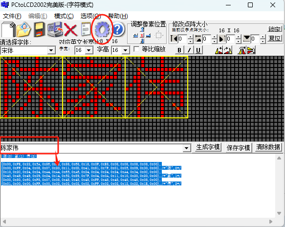
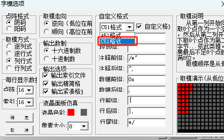
oled_font.h
const char Font_Chinese[][32]=
{
{0x00,0xFE,0x22,0x5A,0x86,0x08,0x88,0x68,0x18,0x0F,0xE8,0x08,0x08,0x08,0x08,0x00},
{0x00,0xFF,0x04,0x08,0x07,0x20,0x11,0x0D,0x41,0x81,0x7F,0x01,0x05,0x09,0x30,0x00},/*"陈",0*/
{0x10,0x2C,0x24,0x24,0xA4,0xA4,0x65,0xA6,0x24,0x24,0x24,0x24,0xA4,0x34,0x0C,0x00},
{0x40,0x49,0x49,0x29,0x24,0x14,0x52,0x89,0x7F,0x04,0x0A,0x11,0x10,0x20,0x20,0x00},/*"家",1*/
{0x00,0x80,0x60,0xF8,0x07,0x08,0x48,0x48,0x48,0xFF,0x48,0x48,0x48,0x48,0x08,0x00},
{0x01,0x00,0x00,0xFF,0x00,0x02,0x02,0x02,0x02,0xFF,0x02,0x02,0x12,0x22,0x1E,0x00},/*"伟",2*/
};
oled.c
#include "stm32f10x.h"
#include "OLED_Font.h"

/*引脚配置*/
#define OLED_W_SCL(x)		GPIO_WriteBit(GPIOB, GPIO_Pin_8, (BitAction)(x))
#define OLED_W_SDA(x)		GPIO_WriteBit(GPIOB, GPIO_Pin_9, (BitAction)(x))

/*引脚初始化*/
void OLED_I2C_Init(void)
{
    RCC_APB2PeriphClockCmd(RCC_APB2Periph_GPIOB, ENABLE);

	GPIO_InitTypeDef GPIO_InitStructure;
 	GPIO_InitStructure.GPIO_Mode = GPIO_Mode_Out_OD;
	GPIO_InitStructure.GPIO_Speed = GPIO_Speed_50MHz;
	GPIO_InitStructure.GPIO_Pin = GPIO_Pin_8;
 	GPIO_Init(GPIOB, &GPIO_InitStructure);
	GPIO_InitStructure.GPIO_Pin = GPIO_Pin_9;
 	GPIO_Init(GPIOB, &GPIO_InitStructure);

	OLED_W_SCL(1);
	OLED_W_SDA(1);
}

/**
  * @brief  I2C开始
  * @param  无
  * @retval 无
  */
void OLED_I2C_Start(void)
{
	OLED_W_SDA(1);
	OLED_W_SCL(1);
	OLED_W_SDA(0);
	OLED_W_SCL(0);
}

/**
  * @brief  I2C停止
  * @param  无
  * @retval 无
  */
void OLED_I2C_Stop(void)
{
	OLED_W_SDA(0);
	OLED_W_SCL(1);
	OLED_W_SDA(1);
}

/**
  * @brief  I2C发送一个字节
  * @param  Byte 要发送的一个字节
  * @retval 无
  */
void OLED_I2C_SendByte(uint8_t Byte)
{
	uint8_t i;
	for (i = 0; i < 8; i++)
	{
		OLED_W_SDA(!!(Byte & (0x80 >> i)));
		OLED_W_SCL(1);
		OLED_W_SCL(0);
	}
	OLED_W_SCL(1);	//额外的一个时钟,不处理应答信号
	OLED_W_SCL(0);
}

/**
  * @brief  OLED写命令
  * @param  Command 要写入的命令
  * @retval 无
  */
void OLED_WriteCommand(uint8_t Command)
{
	OLED_I2C_Start();
	OLED_I2C_SendByte(0x78);		//从机地址
	OLED_I2C_SendByte(0x00);		//写命令
	OLED_I2C_SendByte(Command);
	OLED_I2C_Stop();
}

/**
  * @brief  OLED写数据
  * @param  Data 要写入的数据
  * @retval 无
  */
void OLED_WriteData(uint8_t Data)
{
	OLED_I2C_Start();
	OLED_I2C_SendByte(0x78);		//从机地址
	OLED_I2C_SendByte(0x40);		//写数据
	OLED_I2C_SendByte(Data);
	OLED_I2C_Stop();
}

/**
  * @brief  OLED设置光标位置
  * @param  Y 以左上角为原点,向下方向的坐标,范围:0~7
  * @param  X 以左上角为原点,向右方向的坐标,范围:0~127
  * @retval 无
  */
void OLED_SetCursor(uint8_t Y, uint8_t X)
{
	OLED_WriteCommand(0xB0 | Y);					//设置Y位置
	OLED_WriteCommand(0x10 | ((X & 0xF0) >> 4));	//设置X位置高4位
	OLED_WriteCommand(0x00 | (X & 0x0F));			//设置X位置低4位
}

/**
  * @brief  OLED清屏
  * @param  无
  * @retval 无
  */
void OLED_Clear(void)
{
	uint8_t i, j;
	for (j = 0; j < 8; j++)
	{
		OLED_SetCursor(j, 0);
		for(i = 0; i < 128; i++)
		{
			OLED_WriteData(0x00);
		}
	}
}

/**
  * @brief  OLED显示一个字符
  * @param  Line 行位置,范围:1~4
  * @param  Column 列位置,范围:1~16
  * @param  Char 要显示的一个字符,范围:ASCII可见字符
  * @retval 无
  */
void OLED_ShowChar(uint8_t Line, uint8_t Column, char Char)
{
	uint8_t i;
	OLED_SetCursor((Line - 1) * 2, (Column - 1) * 8);		//设置光标位置在上半部分
	for (i = 0; i < 8; i++)
	{
		OLED_WriteData(OLED_F8x16[Char - ' '][i]);			//显示上半部分内容
	}
	OLED_SetCursor((Line - 1) * 2 + 1, (Column - 1) * 8);	//设置光标位置在下半部分
	for (i = 0; i < 8; i++)
	{
		OLED_WriteData(OLED_F8x16[Char - ' '][i + 8]);		//显示下半部分内容
	}
}

/**
  * @brief  OLED显示字符串
  * @param  Line 起始行位置,范围:1~4
  * @param  Column 起始列位置,范围:1~16
  * @param  String 要显示的字符串,范围:ASCII可见字符
  * @retval 无
  */
void OLED_ShowString(uint8_t Line, uint8_t Column, char *String)
{
	uint8_t i;
	for (i = 0; String[i] != '\0'; i++)
	{
		OLED_ShowChar(Line, Column + i, String[i]);
	}
}

/**
  * @brief  OLED次方函数
  * @retval 返回值等于X的Y次方
  */
uint32_t OLED_Pow(uint32_t X, uint32_t Y)
{
	uint32_t Result = 1;
	while (Y--)
	{
		Result *= X;
	}
	return Result;
}

/**
  * @brief  OLED显示数字(十进制,正数)
  * @param  Line 起始行位置,范围:1~4
  * @param  Column 起始列位置,范围:1~16
  * @param  Number 要显示的数字,范围:0~4294967295
  * @param  Length 要显示数字的长度,范围:1~10
  * @retval 无
  */
void OLED_ShowNum(uint8_t Line, uint8_t Column, uint32_t Number, uint8_t Length)
{
	uint8_t i;
	for (i = 0; i < Length; i++)
	{
		OLED_ShowChar(Line, Column + i, Number / OLED_Pow(10, Length - i - 1) % 10 + '0');
	}
}

/**
  * @brief  OLED显示数字(十进制,带符号数)
  * @param  Line 起始行位置,范围:1~4
  * @param  Column 起始列位置,范围:1~16
  * @param  Number 要显示的数字,范围:-2147483648~2147483647
  * @param  Length 要显示数字的长度,范围:1~10
  * @retval 无
  */
void OLED_ShowSignedNum(uint8_t Line, uint8_t Column, int32_t Number, uint8_t Length)
{
	uint8_t i;
	uint32_t Number1;
	if (Number >= 0)
	{
		OLED_ShowChar(Line, Column, '+');
		Number1 = Number;
	}
	else
	{
		OLED_ShowChar(Line, Column, '-');
		Number1 = -Number;
	}
	for (i = 0; i < Length; i++)
	{
		OLED_ShowChar(Line, Column + i + 1, Number1 / OLED_Pow(10, Length - i - 1) % 10 + '0');
	}
}

/**
  * @brief  OLED显示数字(十六进制,正数)
  * @param  Line 起始行位置,范围:1~4
  * @param  Column 起始列位置,范围:1~16
  * @param  Number 要显示的数字,范围:0~0xFFFFFFFF
  * @param  Length 要显示数字的长度,范围:1~8
  * @retval 无
  */
void OLED_ShowHexNum(uint8_t Line, uint8_t Column, uint32_t Number, uint8_t Length)
{
	uint8_t i, SingleNumber;
	for (i = 0; i < Length; i++)
	{
		SingleNumber = Number / OLED_Pow(16, Length - i - 1) % 16;
		if (SingleNumber < 10)
		{
			OLED_ShowChar(Line, Column + i, SingleNumber + '0');
		}
		else
		{
			OLED_ShowChar(Line, Column + i, SingleNumber - 10 + 'A');
		}
	}
}

/**
  * @brief  OLED显示数字(二进制,正数)
  * @param  Line 起始行位置,范围:1~4
  * @param  Column 起始列位置,范围:1~16
  * @param  Number 要显示的数字,范围:0~1111 1111 1111 1111
  * @param  Length 要显示数字的长度,范围:1~16
  * @retval 无
  */
void OLED_ShowBinNum(uint8_t Line, uint8_t Column, uint32_t Number, uint8_t Length)
{
	uint8_t i;
	for (i = 0; i < Length; i++)
	{
		OLED_ShowChar(Line, Column + i, Number / OLED_Pow(2, Length - i - 1) % 2 + '0');
	}
}

void OLED_ShowChinese(uint8_t Line,uint8_t Column,uint8_t num)
{
	uint8_t i;
	OLED_SetCursor((Line-1)*2,(Column-1)*16);
	for(i=0;i<16;i++)
	{
		OLED_WriteData(Font_Chinese[2*num][i]);
	}
	OLED_SetCursor((Line-1)*2+1,(Column-1)*16);
	for(i=0;i<16;i++)
	{
		OLED_WriteData(Font_Chinese[2*num+1][i]);
	}
}

/**
  * @brief  OLED初始化
  * @param  无
  * @retval 无
  */
void OLED_Init(void)
{
	uint32_t i, j;

	for (i = 0; i < 1000; i++)			//上电延时
	{
		for (j = 0; j < 1000; j++);
	}

	OLED_I2C_Init();			//端口初始化

	OLED_WriteCommand(0xAE);	//关闭显示

	OLED_WriteCommand(0xD5);	//设置显示时钟分频比/振荡器频率
	OLED_WriteCommand(0x80);

	OLED_WriteCommand(0xA8);	//设置多路复用率
	OLED_WriteCommand(0x3F);

	OLED_WriteCommand(0xD3);	//设置显示偏移
	OLED_WriteCommand(0x00);

	OLED_WriteCommand(0x40);	//设置显示开始行

	OLED_WriteCommand(0xA1);	//设置左右方向,0xA1正常 0xA0左右反置

	OLED_WriteCommand(0xC8);	//设置上下方向,0xC8正常 0xC0上下反置

	OLED_WriteCommand(0xDA);	//设置COM引脚硬件配置
	OLED_WriteCommand(0x12);

	OLED_WriteCommand(0x81);	//设置对比度控制
	OLED_WriteCommand(0xCF);

	OLED_WriteCommand(0xD9);	//设置预充电周期
	OLED_WriteCommand(0xF1);

	OLED_WriteCommand(0xDB);	//设置VCOMH取消选择级别
	OLED_WriteCommand(0x30);

	OLED_WriteCommand(0xA4);	//设置整个显示打开/关闭

	OLED_WriteCommand(0xA6);	//设置正常/倒转显示

	OLED_WriteCommand(0x8D);	//设置充电泵
	OLED_WriteCommand(0x14);

	OLED_WriteCommand(0xAF);	//开启显示

	OLED_Clear();				//OLED清屏
}
oled.h
#ifndef __OLED_H
#define __OLED_H

void OLED_Init(void);
void OLED_Clear(void);
void OLED_ShowChar(uint8_t Line, uint8_t Column, char Char);
void OLED_ShowString(uint8_t Line, uint8_t Column, char *String);
void OLED_ShowNum(uint8_t Line, uint8_t Column, uint32_t Number, uint8_t Length);
void OLED_ShowSignedNum(uint8_t Line, uint8_t Column, int32_t Number, uint8_t Length);
void OLED_ShowHexNum(uint8_t Line, uint8_t Column, uint32_t Number, uint8_t Length);
void OLED_ShowBinNum(uint8_t Line, uint8_t Column, uint32_t Number, uint8_t Length);
void OLED_ShowChinese(uint8_t Line,uint8_t Column,uint8_t num);
#endif
main.c
#include "stm32f10x.h"                  // Device header
#include "Delay.h"
#include "OLED.h"

int main(void){

	OLED_Init();//初始化
//	OLED_ShowChar(1,1,'A');//第一行第一列输出字符A
//	OLED_ShowString(1,3,"CHENJIAWEI");//第一行第三列打印字符串
//	OLED_ShowSignedNum(3,1,-66,2);//第三行弟1列打印一个有符号的整数-66
//	OLED_ShowBinNum(2,1,0xAA55,16); //二进制显示1010101001010101
//	OLED_ShowHexNum(3,1,0xAA55,4);//十六进制形式显示AA55
	OLED_ShowChinese(1,1,0);
	OLED_ShowChinese(1,2,1);
	OLED_ShowChinese(1,3,2);
	while(1)
	{

	}
}
项目一 倒计时器
main.c
#include "stm32f10x.h"
#include "OLED.h"
#include "Key.h"
#include "timer.h"
#include "Delay.h"

uint8_t countdown_time = 0; // 单位:秒
uint8_t countdown_active = 0;

int main(void)
{
    SystemInit();

    OLED_Init();       // OLED初始化
    KEY_Init();        // 按键初始化
    Timer_Init();      // 定时器初始化

    OLED_Clear();
    OLED_ShowString(0, 0, "Set Time: 0s");

    static uint8_t last_time = 255;  // 记录上一次显示的秒数

    while (1)
    {
        // 设置时间,每次按下+60秒
        if (KEY1_Pressed())
        {
            if (!countdown_active && countdown_time < 300)
            {
                countdown_time += 20;
                OLED_Clear();
                OLED_ShowString(0, 0, "Set Time:");
                OLED_ShowNum(72, 0, countdown_time, 3, 16);
                OLED_ShowString(100, 0, "s");
            }
        }

        // 启动倒计时
        if (KEY2_Pressed())
        {
            if (countdown_time > 0 && !countdown_active)
            {
                countdown_active = 1;
                Timer_Start();
                last_time = 255;  // 触发强制刷新
            }
        }

        // 倒计时过程,每秒刷新一次屏幕
        if (countdown_active)
        {
            if (last_time != countdown_time)
            {
                last_time = countdown_time;

                OLED_Clear();
                OLED_ShowString(0, 2, "Counting:");
                OLED_ShowNum(72, 2, countdown_time, 3, 16);
                OLED_ShowString(100, 2, "s");

                if (countdown_time == 0)
                {
                    countdown_active = 0;
                    Timer_Stop();

                    OLED_Clear();
                    OLED_ShowString(16, 2, "*** DONE ***");
                    OLED_ShowString(32, 4, "Time's Up!");


                    Delay_ms(3000);

                    OLED_Clear();
                    OLED_ShowString(0, 0, "Set Time: 0s");
                }
            }
        }
    }
}
oled.c
#include "stm32f10x.h"                  // Device header
#include "OLED.h"
#include "i2c.h"
#include "OLED_Font.h"
#include "Delay.h"
#include <math.h>
void OLED_WR_Byte(uint8_t dat, uint8_t cmd)
{
    I2C_Start();
    I2C_SendByte(0x78); // OLED地址
    I2C_WaitAck();
    I2C_SendByte(cmd ? 0x40 : 0x00);
    I2C_WaitAck();
    I2C_SendByte(dat);
    I2C_WaitAck();
    I2C_Stop();
}

void OLED_Set_Pos(uint8_t x, uint8_t y)
{
    OLED_WR_Byte(0xb0 + y, 0);
    OLED_WR_Byte(((x & 0xf0) >> 4) | 0x10, 0);
    OLED_WR_Byte((x & 0x0f), 0);
}

void OLED_Clear(void)
{
    for (uint8_t i = 0; i < 8; i++)
    {
        OLED_WR_Byte(0xb0 + i, 0);
        OLED_WR_Byte(0x00, 0);
        OLED_WR_Byte(0x10, 0);
        for (uint8_t n = 0; n < 128; n++)
            OLED_WR_Byte(0x00, 1);
    }
}

void OLED_ShowChar(uint8_t x, uint8_t y, char chr)
{
    uint8_t c = chr - ' ';
    OLED_Set_Pos(x, y);
    for (uint8_t i = 0; i < 8; i++)
        OLED_WR_Byte(F8X16[c * 16 + i], 1);
    OLED_Set_Pos(x, y + 1);
    for (uint8_t i = 0; i < 8; i++)
        OLED_WR_Byte(F8X16[c * 16 + i + 8], 1);
}

void OLED_ShowString(uint8_t x, uint8_t y, char *str)
{
    while (*str)
    {
        OLED_ShowChar(x, y, *str);
        x += 8;
        if (x > 120) { x = 0; y += 2; }
        str++;
    }
}

void OLED_ShowNum(uint8_t x, uint8_t y, uint16_t num, uint8_t len, uint8_t size)
{
    for (uint8_t t = 0; t < len; t++)
    {
        uint8_t temp = (num / (uint16_t)pow(10, len - t - 1)) % 10;
        OLED_ShowChar(x + (size / 2) * t, y, temp + '0');
    }
}

void OLED_Init(void)
{
    Delay_ms(100);
    OLED_WR_Byte(0xAE, 0); // 关闭显示
    OLED_WR_Byte(0xA8, 0); OLED_WR_Byte(0x3F, 0); // 设置多重比率
    OLED_WR_Byte(0xD3, 0); OLED_WR_Byte(0x00, 0);
    OLED_WR_Byte(0x40, 0); OLED_WR_Byte(0xA1, 0);
    OLED_WR_Byte(0xC8, 0); OLED_WR_Byte(0xDA, 0); OLED_WR_Byte(0x12, 0);
    OLED_WR_Byte(0x81, 0); OLED_WR_Byte(0x7F, 0); OLED_WR_Byte(0xA4, 0);
    OLED_WR_Byte(0xA6, 0); OLED_WR_Byte(0xD5, 0); OLED_WR_Byte(0x80, 0);
    OLED_WR_Byte(0x8D, 0); OLED_WR_Byte(0x14, 0); OLED_WR_Byte(0xAF, 0); // 开启显示
    OLED_Clear();
}
oled.h
#ifndef __OLED_H
#define __OLED_H

#include "stm32f10x.h"

void OLED_Init(void);
void OLED_Clear(void);
void OLED_ShowString(uint8_t x, uint8_t y, char *str);
void OLED_ShowChar(uint8_t x, uint8_t y, char chr);
void OLED_ShowNum(uint8_t x, uint8_t y, uint16_t num, uint8_t len, uint8_t size);

#endif
key.c
#include "Key.h"
#include "Delay.h"

void KEY_Init(void)
{
    RCC_APB2PeriphClockCmd(RCC_APB2Periph_GPIOB, ENABLE);
    GPIO_InitTypeDef GPIO_InitStructure;
    GPIO_InitStructure.GPIO_Mode = GPIO_Mode_IPU;
    GPIO_InitStructure.GPIO_Pin = GPIO_Pin_1 | GPIO_Pin_11;
    GPIO_InitStructure.GPIO_Speed = GPIO_Speed_50MHz;
    GPIO_Init(GPIOB, &GPIO_InitStructure);
}

uint8_t KEY1_Pressed(void)
{
    if (!GPIO_ReadInputDataBit(GPIOB, GPIO_Pin_1))
    {
        Delay_ms(20);
        if (!GPIO_ReadInputDataBit(GPIOB, GPIO_Pin_1))
        {
            while (!GPIO_ReadInputDataBit(GPIOB, GPIO_Pin_1));
            return 1;
        }
    }
    return 0;
}

uint8_t KEY2_Pressed(void)
{
    if (!GPIO_ReadInputDataBit(GPIOB, GPIO_Pin_11))
    {
        Delay_ms(20);
        if (!GPIO_ReadInputDataBit(GPIOB, GPIO_Pin_11))
        {
            while (!GPIO_ReadInputDataBit(GPIOB, GPIO_Pin_11));
            return 1;
        }
    }
    return 0;
}
key.h
#ifndef __KEY_H
#define __KEY_H

#include "stm32f10x.h"

void KEY_Init(void);
uint8_t KEY1_Pressed(void);
uint8_t KEY2_Pressed(void);

#endif
timer.c
#include "timer.h"

extern uint8_t countdown_time;

void Timer_Init(void)
{
    RCC_APB1PeriphClockCmd(RCC_APB1Periph_TIM2, ENABLE);

    TIM_TimeBaseInitTypeDef TIM_TimeBaseStructure;
    NVIC_InitTypeDef NVIC_InitStructure;

    TIM_TimeBaseStructure.TIM_Period = 10000-1;
    TIM_TimeBaseStructure.TIM_Prescaler =  7200-1;
    TIM_TimeBaseStructure.TIM_ClockDivision = TIM_CKD_DIV1;
    TIM_TimeBaseStructure.TIM_CounterMode = TIM_CounterMode_Up;

    TIM_TimeBaseInit(TIM2, &TIM_TimeBaseStructure);

    NVIC_InitStructure.NVIC_IRQChannel = TIM2_IRQn;
    NVIC_InitStructure.NVIC_IRQChannelPreemptionPriority = 1;
    NVIC_InitStructure.NVIC_IRQChannelSubPriority = 1;
    NVIC_InitStructure.NVIC_IRQChannelCmd = ENABLE;
    NVIC_Init(&NVIC_InitStructure);

    TIM_ITConfig(TIM2, TIM_IT_Update, ENABLE);
}

void Timer_Start(void)
{
    TIM_Cmd(TIM2, ENABLE);
}

void Timer_Stop(void)
{
    TIM_Cmd(TIM2, DISABLE);
}

void TIM2_IRQHandler(void)
{
    if (TIM_GetITStatus(TIM2, TIM_IT_Update) != RESET)
    {
        TIM_ClearITPendingBit(TIM2, TIM_IT_Update);
        if (countdown_time > 0)
            countdown_time--;
    }
}
timer.h
#ifndef __TIMER_H
#define __TIMER_H

#include "stm32f10x.h"
extern uint8_t countdown_time;
void Timer_Init(void);
void Timer_Start(void);
void Timer_Stop(void);

#endif
i2c.c
#include "i2c.h"
#include "Delay.h"

#define I2C_SCL_PIN  GPIO_Pin_8
#define I2C_SDA_PIN  GPIO_Pin_9
#define I2C_PORT     GPIOB

void I2C_GPIO_Config(void)
{
    RCC_APB2PeriphClockCmd(RCC_APB2Periph_GPIOB, ENABLE);

    GPIO_InitTypeDef GPIO_InitStructure;
    GPIO_InitStructure.GPIO_Pin = I2C_SCL_PIN | I2C_SDA_PIN;
    GPIO_InitStructure.GPIO_Mode = GPIO_Mode_Out_OD;
    GPIO_InitStructure.GPIO_Speed = GPIO_Speed_50MHz;
    GPIO_Init(I2C_PORT, &GPIO_InitStructure);
}

static void SDA_OUT(void)
{
    GPIO_InitTypeDef GPIO_InitStructure;
    GPIO_InitStructure.GPIO_Pin = I2C_SDA_PIN;
    GPIO_InitStructure.GPIO_Mode = GPIO_Mode_Out_OD;
    GPIO_InitStructure.GPIO_Speed = GPIO_Speed_50MHz;
    GPIO_Init(I2C_PORT, &GPIO_InitStructure);
}

static void SDA_IN(void)
{
    GPIO_InitTypeDef GPIO_InitStructure;
    GPIO_InitStructure.GPIO_Pin = I2C_SDA_PIN;
    GPIO_InitStructure.GPIO_Mode = GPIO_Mode_IPU;
    GPIO_Init(I2C_PORT, &GPIO_InitStructure);
}

void I2C_Start(void)
{
    I2C_GPIO_Config();
    SDA_OUT();
    GPIO_SetBits(I2C_PORT, I2C_SCL_PIN | I2C_SDA_PIN);
    Delay_us(4);
    GPIO_ResetBits(I2C_PORT, I2C_SDA_PIN);
    Delay_us(4);
    GPIO_ResetBits(I2C_PORT, I2C_SCL_PIN);
}

void I2C_Stop(void)
{
    SDA_OUT();
    GPIO_ResetBits(I2C_PORT, I2C_SCL_PIN);
    GPIO_ResetBits(I2C_PORT, I2C_SDA_PIN);
    Delay_us(4);
    GPIO_SetBits(I2C_PORT, I2C_SCL_PIN);
    GPIO_SetBits(I2C_PORT, I2C_SDA_PIN);
    Delay_us(4);
}

uint8_t I2C_WaitAck(void)
{
    uint8_t ucErrTime = 0;
    SDA_IN();
    GPIO_SetBits(I2C_PORT, I2C_SDA_PIN);
    Delay_us(1);
    GPIO_SetBits(I2C_PORT, I2C_SCL_PIN);
    Delay_us(1);

    while (GPIO_ReadInputDataBit(I2C_PORT, I2C_SDA_PIN))
    {
        ucErrTime++;
        if (ucErrTime > 250)
        {
            I2C_Stop();
            return 1;
        }
    }

    GPIO_ResetBits(I2C_PORT, I2C_SCL_PIN);
    return 0;
}

void I2C_Ack(void)
{
    GPIO_ResetBits(I2C_PORT, I2C_SCL_PIN);
    SDA_OUT();
    GPIO_ResetBits(I2C_PORT, I2C_SDA_PIN);
    Delay_us(2);
    GPIO_SetBits(I2C_PORT, I2C_SCL_PIN);
    Delay_us(2);
    GPIO_ResetBits(I2C_PORT, I2C_SCL_PIN);
}

void I2C_NAck(void)
{
    GPIO_ResetBits(I2C_PORT, I2C_SCL_PIN);
    SDA_OUT();
    GPIO_SetBits(I2C_PORT, I2C_SDA_PIN);
    Delay_us(2);
    GPIO_SetBits(I2C_PORT, I2C_SCL_PIN);
    Delay_us(2);
    GPIO_ResetBits(I2C_PORT, I2C_SCL_PIN);
}

void I2C_SendByte(uint8_t byte)
{
    SDA_OUT();
    GPIO_ResetBits(I2C_PORT, I2C_SCL_PIN);
    for (uint8_t i = 0; i < 8; i++)
    {
        if (byte & 0x80)
            GPIO_SetBits(I2C_PORT, I2C_SDA_PIN);
        else
            GPIO_ResetBits(I2C_PORT, I2C_SDA_PIN);
        byte <<= 1;
       Delay_us(2);
        GPIO_SetBits(I2C_PORT, I2C_SCL_PIN);
       Delay_us(2);
        GPIO_ResetBits(I2C_PORT, I2C_SCL_PIN);
     Delay_us(2);
    }
}

uint8_t I2C_ReadByte(uint8_t ack)
{
    uint8_t receive = 0;
    SDA_IN();
    for (uint8_t i = 0; i < 8; i++)
    {
        GPIO_ResetBits(I2C_PORT, I2C_SCL_PIN);
        Delay_us(2);
        GPIO_SetBits(I2C_PORT, I2C_SCL_PIN);
        receive <<= 1;
        if (GPIO_ReadInputDataBit(I2C_PORT, I2C_SDA_PIN)) receive++;
        Delay_us(1);
    }

    if (!ack)
        I2C_NAck();
    else
        I2C_Ack();

    return receive;
}
i2c.h
#ifndef __I2C_H
#define __I2C_H

#include "stm32f10x.h"

void I2C_Start(void);
void I2C_Stop(void);
void I2C_SendByte(uint8_t byte);
uint8_t I2C_ReadByte(uint8_t ack);
uint8_t I2C_WaitAck(void);
void I2C_Ack(void);
void I2C_NAck(void);
void I2C_GPIO_Config(void);

#endif
串口
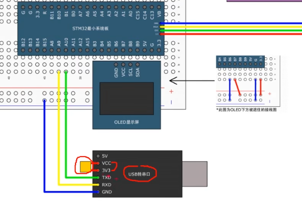

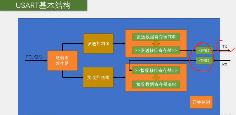
初始化
Ctrl+Alt+空格
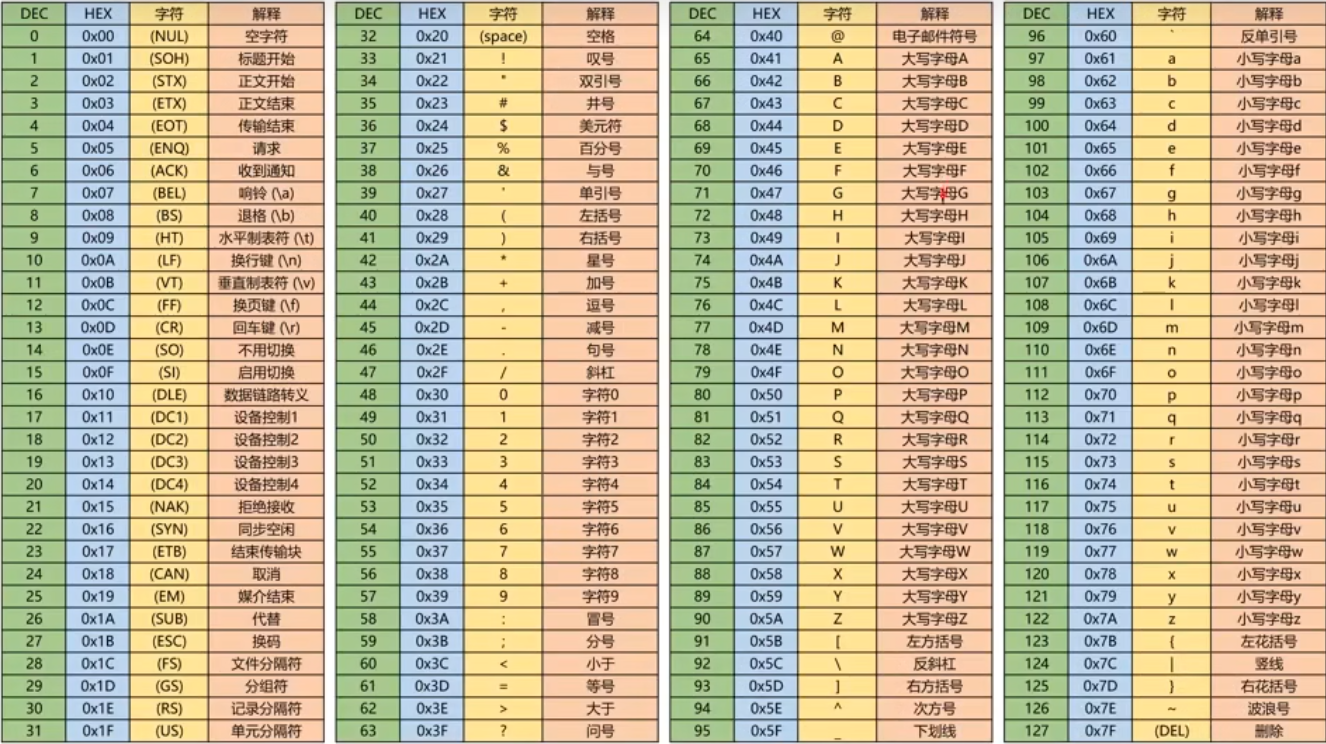
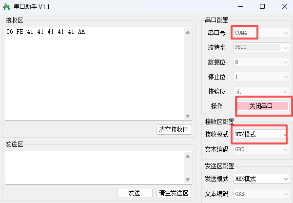
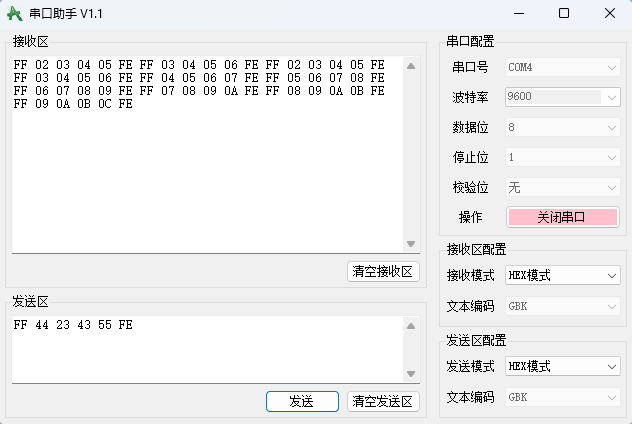
9-1 串口发送HEX数据包
main.c
#include "stm32f10x.h"                  // Device header
#include "Delay.h"
#include "OLED.h"
#include "Serial.h"
#include "Key.h"

uint8_t KeyNum;

	int main(void)
	{

		OLED_Init();
		Key_Init();
		Serial_Init();

		OLED_ShowString(1,1,"TxPacket");
		OLED_ShowString(3,1,"RxPacket");

		Serial_TxPacket[0]=0x01;
		Serial_TxPacket[1]=0x02;
		Serial_TxPacket[2]=0x03;
		Serial_TxPacket[3]=0x04;


		while (1)
		{
			KeyNum = Key_GetNum();
			if(KeyNum ==1)
			{
				Serial_TxPacket[0] ++;
				Serial_TxPacket[1] ++;
				Serial_TxPacket[2] ++;
				Serial_TxPacket[3] ++;

				Serial_SendPacket();

				OLED_ShowHexNum(2,1,Serial_TxPacket[0],2);
				OLED_ShowHexNum(2,4,Serial_TxPacket[1],2);
				OLED_ShowHexNum(2,7,Serial_TxPacket[2],2);
				OLED_ShowHexNum(2,10,Serial_TxPacket[3],2);
			}
			if(Serial_GetRxFlag()==1)
			{
				OLED_ShowHexNum(4,1,Serial_RxPacket[0],2);
				OLED_ShowHexNum(4,4,Serial_RxPacket[1],2);
				OLED_ShowHexNum(4,7,Serial_RxPacket[2],2);
				OLED_ShowHexNum(4,10,Serial_RxPacket[3],2);
			}
		}
	}
serial.c
#include "stm32f10x.h" // Device header
#include <stdio.h>
#include <stdarg.h>
uint8_t Serial_TxPacket[4];
uint8_t Serial_RxPacket[4];
uint8_t Serial_RxFlag; //收到一个数据包就值1
/**
串口初始化
*/
void Serial_Init(void)
{
RCC_APB2PeriphClockCmd(RCC_APB2Periph_USART1,ENABLE);
RCC_APB2PeriphClockCmd(RCC_APB2Periph_GPIOA,ENABLE);
GPIO_InitTypeDef GPIO_InitStructure;
GPIO_InitStructure.GPIO_Mode = GPIO_Mode_AF_PP;
GPIO_InitStructure.GPIO_Pin = GPIO_Pin_9;
GPIO_InitStructure.GPIO_Speed = GPIO_Speed_50MHz;
GPIO_Init(GPIOA, &GPIO_InitStructure); //将PA1和PA2引脚初始化为推挽输出
GPIO_InitStructure.GPIO_Mode = GPIO_Mode_IPU;
GPIO_InitStructure.GPIO_Pin = GPIO_Pin_10;
GPIO_InitStructure.GPIO_Speed = GPIO_Speed_50MHz;
GPIO_Init(GPIOA, &GPIO_InitStructure);
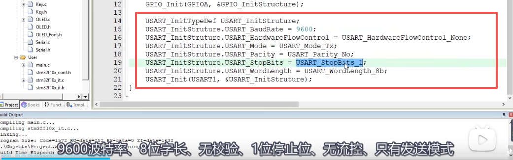
USART_InitTypeDef USART_InitStruture;
USART_InitStruture.USART_BaudRate= 9600;
USART_InitStruture.USART_HardwareFlowControl=USART_HardwareFlowControl_None;
USART_InitStruture.USART_Mode=USART_Mode_Tx | USART_Mode_Rx; // 同时使能发送和接收
USART_InitStruture.USART_Parity=USART_Parity_No;
USART_InitStruture.USART_StopBits=USART_StopBits_1;
USART_InitStruture.USART_WordLength=USART_WordLength_8b;
USART_Init(USART1,&USART_InitStruture);
// 使能接收非空中断
USART_ITConfig(USART1,USART_IT_RXNE,ENABLE);
NVIC_PriorityGroupConfig(NVIC_PriorityGroup_2); // 配置NVIC中断分组
// 配置USART1中断
NVIC_InitTypeDef NVIC_InitStructure;
NVIC_InitStructure.NVIC_IRQChannel=USART1_IRQn;
NVIC_InitStructure.NVIC_IRQChannelCmd=ENABLE;
NVIC_InitStructure.NVIC_IRQChannelPreemptionPriority=1;// 抢占优先级
NVIC_InitStructure.NVIC_IRQChannelSubPriority=1;// 子优先级
NVIC_Init(&NVIC_InitStructure);
USART_Cmd(USART1,ENABLE); // 使能USART1
}
/**
串口发送一个字节
*/
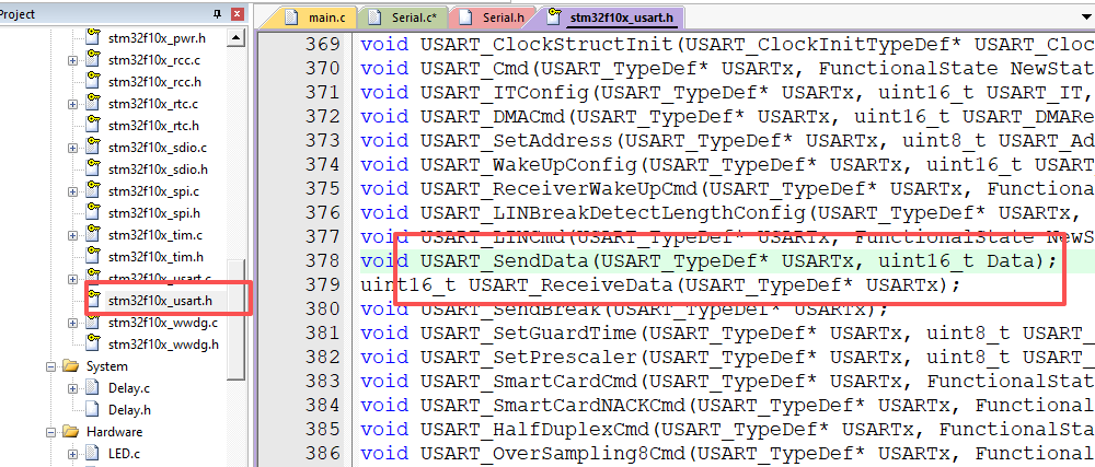
void Serial_SendByte(uint8_t Byte)
{
USART_SendData(USART1,Byte);
while(USART_GetFlagStatus(USART1,USART_FLAG_TXE)== RESET);
}
/**
发送一个数组
*/
void Serial_SendArray(uint8_t *Array, uint16_t Length)
{
uint16_t i;
for (i=0;i< Length;i++)
{
Serial_SendByte(Array[i]);
}
}
/**
发送一个字符串
*/
void Serial_SendString(char *String)
{
uint8_t i;
for(i=0;String[i]!='\0';i++)
{
Serial_SendByte(String[i]);
}
}
/**
次方函数,返回值等于x的y次方
*/
uint32_t Serial_Pow(uint32_t X,uint32_t Y)
{
uint32_t Result =1;
while(Y --)
{
Result *=X;
}
return Result;
}
/**
串口发送数字
*/
void Serial_SendNumber(uint32_t Number,uint8_t length)
{
uint8_t i;
for(i=0; i<length;i++)
{
Serial_SendByte(Number/Serial_Pow(10,length-i-1)%10+'0');
}
}
/**
使用printf需要重定向的底层函数
*/
int fputc(int ch, FILE *f)
{
Serial_SendByte(ch);
return ch;
}
/**
自己封装的printf函数
*/
void Serial_Printf(char *format, ...)
{
char String[100];
va_list arg;
va_start(arg,format);
vsprintf(String,format,arg);
va_end(arg);
Serial_SendString(String);
}
void Serial_SendPacket(void)
{
Serial_SendByte(0xFF);
Serial_SendArray(Serial_TxPacket,4);
Serial_SendByte(0xFE);
}
/**
获取串口接收标注位,串口接收标志位,范围:0~1,接收到数据后,标志位置1,读取后标志位自动清零
*/
uint8_t Serial_GetRxFlag(void)
{
if(Serial_RxFlag ==1)
{
Serial_RxFlag =0;
return 1;
}
return 0;
}
/**
函 数:USART1中断函数
*/
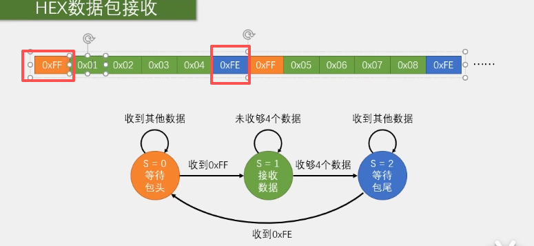
void USART1_IRQHandler(void)
{
static uint8_t RxState=0;
static uint8_t pRxPacket=0;
if (USART_GetFlagStatus(USART1,USART_IT_RXNE)== SET)
{
uint8_t RxData = USART_ReceiveData(USART1);
if(RxState==0)
{
if(RxData==0xFF)// 检测到帧头0xFF
{
RxState=1; // 进入数据接收状态
pRxPacket = 0; // 重置数据包指针
}
}
else if (RxState==1)
{
Serial_RxPacket[pRxPacket] = RxData; // 存储数据
pRxPacket++;
if(pRxPacket>=4) // 收满4个字节数据
{
RxState = 2; // 进入帧尾检查状态
}
}
else if (RxState==2)
{
if (RxData == 0xFE)
{
RxState = 0;// 回到初始状态
Serial_RxFlag =1; // 设置接收完成标志
}
}
USART_ClearITPendingBit(USART1,USART_IT_RXNE);
}
}
serial.h
#ifndef __SERIAL_H
#define __SERIAL_H


#include <stdio.h>

extern uint8_t Serial_TxPacket[];
extern uint8_t Serial_RxPacket[];
void Serial_SendByte(uint8_t Byte);
void Serial_Init(void);
void Serial_SendArray(uint8_t *Array, uint16_t Length);
void Serial_SendString(char *String);
void Serial_Printf(char *format,...);
void Serial_SendPacket(void);
uint8_t Serial_GetRxFlag(void);
void USART1_IRQHandler(void);

#endif

 浙公网安备 33010602011771号