TinyOS功率编程指南
参考文档:CC2420 datasheet: http://www.ti.com/lit/gpn/cc2420
第一章:
RF Frequency Range: 2400 2483.5 MHz, Programmable in 1 MHz steps, 5 MHz steps
Nominal output power: -3dBm 最小 0dBm 常规, Delivered to a single ended 50 load through a balun. [1] requires minimum –3 dBm
Programmable output power range: 24 dB标准, The output power is programmable in 8 steps from approximately –24 to 0 dBm.
Receiver Sensitivity: -90最小, -95 dBm标准, PER = 1%, as specified by [1] Measured in a 50 single-ended load through a balun. [1] requires –85 dBm
Carrier sense level − 77 dBm Programmable in RSSI.CCA_THR
RSSI dynamic range 100 dB The range is approximately from –100 dBm to 0 dBm
RSSI accuracy 6 dB See page 48 for details
RSSI linearity 3 dB
RSSI average time 128 s 8 symbol periods, as specified by
23章 RSSI/能量检测
CC2420有一个内置的RSSI(接收信号强度指示器),提供一个数字值,可以从8位读取,有符号位的RSSI两个补码寄存器中读取。
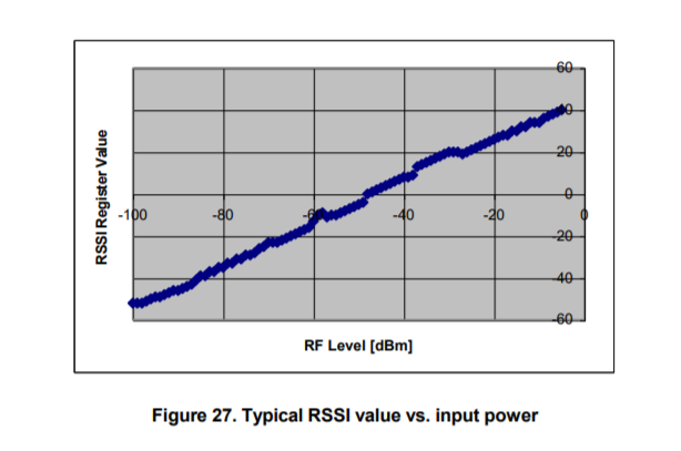
其中RSSI偏移是在系统开发期间从前端增益的经验上发现的。RSSI偏移量约为-45。例如,如果从RssI寄存器读取一个值-20,射频输入功率大约是- 65dbm。RSSI值总是在8个符号周期(128 us)上取平均值,根据[11.]RSSI有效状态位(表5)指示RSSI值何时有效,这意味着接收器已经启用至少8个符号周期作为输入功率函数的RSSI VAL读数的典型图如图所示27. 从图中可以看出,从C2420读取的RSSI是非常线性的,其动态范围约为100dbRSSI登记簿价值RSSI。RSSI瓦尔可以表示为RP引脚处的功率P,公式如下:RSSI登记簿价值RSSI。RSSI瓦尔在RSSI生效后,对每个符号进行计算并不断更新。P = RSSI_VAL [Rssioffset [dbm]
RSSI值总是在8个符号周期(128 us)上取平均值,根据[11.]RSSI有效状态位(表5)指示RSSI值何时有效,这意味着接收器已经启用至少8个符号周期。
RSSI寄存器值RSSI。RSSI值可以用下式表示,P为射频点阵上的功率: P = Rssi Val + Rssi Offset[dbm]
其中RSSI偏移是在系统开发期间从前端增益的经验上发现的。RSSI偏移量约为-45。例如,如果从RsSI寄存器读取-20的值,射频输入能量大约是- 65dbm,
典型的RsSI VAL读取作为输入功率的函数的图如图27所示。从图中可以看出,从C02420读取的RSSI是线性的,其动态范围约为100db。
RSSI寄存器值RSSI,在RSSI生效后,计算并不断更新每个符号的RSSI值
24链路质量指示
链路质量指示(LQI)测量是对接收数据包的强度和/或质量的一种表征,由[1]定义。MAC软件可以使用上一节描述的RSSI值来产生LQI值。[1]要求LQI值限制在0到255的范围内,并且至少有8个惟一值。软件负责为给定的应用程序生成适当的LQl值直接使用RSSI值来计算LQl值有一个缺点,即信道带宽内的窄带干扰会增加LQI值,但实际上会降低链路的真实质量。因此,B2420也提供了每个传入数据包的平均相关值,基于SFD后面的第8个符号。这个无符号的7位值可以被看作是“芯片错误率”的测量,尽管BG2420不做芯片决策。
正如第38页的帧检查序列部分所描述的,MDMCTRLO时,第一个8个符号的平均相关值被附加到每一接收帧,连同RSSI和CRC OK/not OK。设置AUTOCRC。~110的相关值表示最大质量帧,而~50的值通常是CR2420检测到的最低质量帧软件必须将相关值转换为[1]定义的0-255范围,例如:LQI = (CORR-a) .b限制在0-255范围内,其中a和b是根据每个测量值作为相关值的函数经验地找到的。也可以使用RSSI和相关值的组合来生成LQl值。
25 Clear Channel Assessment
The clear channel assessment signal is based on the measured RSSI value and a programmable threshold. The clear channel assessment function is used to implement the CSMA-CA functionality specified in [1]. CCA is valid when the receiver has been enabled for at least 8 symbol periods.
Carrier sense threshold level is programmed by RSSI.CCA_THR. The threshold value can be programmed in steps of 1 dB. A CCA hysteresis can also be programmed in the MDMCTRL0.CCA_HYST control bits
All 3 CCA modes specified by [1] are implemented in CC2420. They are set in MDMCTRL0.CCA_MODE, as can be seen in the register description. The different modes are:
0 Reserved 1 Clear channel when received energy is below threshold. 2 Clear channel when not receiving valid IEEE 802.15.4 data. 3 Clear channel when energy is below threshold and not receiving valid IEEE 802.15.4 data
Clear channel assessment is available on the CCA output pin. CCA is active high, but the polarity may be changed by setting the IOCFG0.CCA_POLARITY control bit.
Implementing CSMA-CA may easiest be done by using the STXONCCA command strobe, as described in the Radio control state machine section on page 43. Transmission will then only start if the channel is clear. The TX_ACTIVE status bit (see Table 5) may be used to detect the result of the CCA.

25 Clear Channel Assessment

 浙公网安备 33010602011771号