

High accuracy voltage regulator
High accuracy voltage regulator
Good morning everybody,
I want to make a accurate voltage regulator based on the Basic Stamp.
Total range 0-10 V and a resolution of eg 5 mV. So this means 2000 steps.
Maximum current around 250 mA.
I tried to do something with the AD5220 or PWM command but only 255 steps are available.
Someone who has a good idea ?
BR, Dries
You will need to use a high accuracy digital to analog converter like www.maxim-ic.com/quick_view2.cfm/qv_pk/2113.
There are plenty of others on the market. Anything that uses the SPI protocol for control and is 12 bit (0-4.095V) should work.
You will need some kind of power op-amp to take this voltage and amplify it precisely to 10V at 250mA. I can't help you with that,
perhaps someone else may have some ideas, but I'm sure some web searching will also give you ideas on that.
Here's one example of the sort of op-amp needed: focus.ti.com/lit/ds/symlink/opa547.pdf
If you only need to source current and not sink it as well,
you could get by with a garden-variety op amp and a pass transistor. Here's the basic topology:
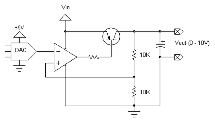
Aside from the two voltage divider resistors being equal,
I have no idea what component values to recommend.
You would have to experiment to get the best stability.
I guess I should qualify what I mean by "garden-variety op amp",
since there are some minimum requirements:
1) The input common mode range has to include ground, and
2) the output high voltage should be capable of reaching Vin.
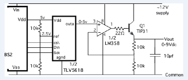
Here is another circuit, similar to Phil's,
except it uses an NPN transistor with the output taken from the emitter
instead of a PNP with output taken from the collector.
This circuit uses one of the two DAC outputs of the TLV5618 12 bit DAC.
The power supply has to at least 3 or 4 Volts above the desired output,
because of overhead of the LM358 op-amp plus the overhead of the transistor.
There are better choices for the output transistor and op-amp if you have constraints on the input power supply.
In terms of circuit configurations, in Phil's circuit with the PNP, the transistor common emitter gain is inside the feedback loop,
which makes it harder to stabilize and it will require a relatively large output capacitor.
The NPN follower gain is x1, which makes it easier to stabilize with a small capacitor.,
and base current contributes to the output current.
But the PNP circuit is the best if you need to operate very close to the power supply rail.
Another option, if you really don't need to get down to zero volts,
is to use a standard voltage regulator controlled by a digital potentiometer.
Those usually have a minimum voltage of something like 1.25 volts.
The circuit itself can regulate down to low voltages.
For precision, you will need to put in an adjustment trimmer, either at the reference side or at the feedback side.
-- 12-turn adjustment trimmer of 1 kOhm between the two 10 kOhm fixed resistors.
Adjust the output to 0.0025 volts per bit. That is 4 bit steps for each 10 millivolts at the output. 4000 steps to 10.0 volts.
-- The 5 volt supply may not be a good enough reference for a precision application.
Change the reference to a 2.5 volt precision reference (e.g. LM385-2.5) in place of the lower 10 kOhms on the ADC ref input.
The adjustment trimmer is still needed on the feedback node, between the two 10k resistors.
-- To get up to 10.00 volts, it will probably take a 13 or 14 volt supply to the LM358 and TIP31.
The Stamp could operate off a different supply. Or you could buy a rail-to-rail op amp and a higher gain transistor.

 浙公网安备 33010602011771号