
V-rep学习笔记:视觉传感器2
视觉传感器的属性设置栏中还有如下几个选项:
- Ignore RGB info (faster): if selected, the RGB information of the sensor (i.e. the color) will be ignored so that it can operate faster. Use this option if you only rely on the depth information of the sensor. 当只需要获取深度图像时就可以勾选这一选项,以提高运行速度。
- Ignore depth info (faster): if selected, the depth information of the sensor will be ignored so that it can operate faster. Use this option if you do not intend to use the depth information of the sensor. 只需要彩色图像时勾选这一选项。
- Packet1 is blank (faster): if selected, then V-REP won't automatically extract specific information from acquired images, so that it can operate faster. Use this option if you do not intend to use the first packet of auxiliary values returned by API functions simReadVisionSensor or simHandleVisionSensor. 当不需要使用API获取图像中的特定信息时(这些信息保存在Packet1中),可以勾选这一选项。
15 auxiliary values (default): the values are calculated over all the image pixels and represent the minimum of intensity, red, green, blue, depth value, the maximum of intensity, red, green, blue, depth value, and the average of intensity, red, green, blue, depth value. On a higher resolution image, computation might slow down vision sensors, and if those values are not used, their calculation can be turned off in the vision sensor properties (Packet1 is blank (faster)). Packet1中会保存图像上的特定信息(灰度、RGB、深度的最小/最大/平均值),这些信息通过遍历图中所有的像素点获得,因此对于分辨率很大的图像计算会变慢。$$Packet1 = \{I_{min},R_{min},G_{min},B_{min},D_{min},\quad I_{max},R_{max},G_{max},B_{max},D_{max},\quad I_{avg},R_{avg},G_{avg},B_{avg},D_{avg}\}$$
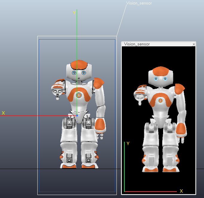
视觉传感器的Z轴沿着视线方向,Y轴代表Up方向,X轴垂直于Y/Z轴指向传感器向左边。如下图所示,将传感器放在机器人正前方,可以看出获得的图像跟人眼观察到的一样,没有镜像。图像的X轴与视觉传感器的X轴方向相反,Y轴方向相同:
- 深度图(depth map)
为了简单的显示深度信息,将filter设置为如下: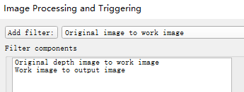
在场景中建立如下模型:4个大小相同的立方体(设置为Renderable属性),边长为0.5m,离地面高度分别为0m,0.25,0.5m,1m。将摄像机置于地面下方1mm处,near clipping plane设为最小值(1.00e-04m),far clipping plane设为1m;视场Orthographic size设为1m,X/Y分辨率均设为2

点击开始仿真按钮,在Floating view中将会显示深度图。亮度越小(越黑/深度值越小)代表离摄像机越近,亮度越大(越白/深度值越大)代表离摄像机越远。如果要获得具体的深度数值可以调用simGetVisionSensorDepthBuffer函数:
table depthBuffer = simGetVisionSensorDepthBuffer(number sensorHandle, number posX=0,number posY=0, number sizeX=0,number sizeY=0)
其中depthBuffer一维表保存了图像上指定大小的深度数据。注意表中的数值不是真正的距离,而是归一化的数值,离传感器最近的值为0,最远的值为1,因此如果已知剪切平面的位置就可以计算出真实的深度。Returned values are in the range of 0~1 (0=closest to sensor (i.e. close clipping plane), 1=farthest from sensor (i.e. far clipping plane)) 。由于图像的水平/垂直分辨率均设置为2,因此depthBuffer包含了4个像素点的深度信息:
-- pixel(1,1) distance is at depthBuffer[1]
-- pixel(1,2) distance is at depthBuffer[2]
-- pixel(2,1) distance is at depthBuffer[3]
-- pixel(2,2) distance is at depthBuffer[4]
下面代码获取了4个像素点的深度信息,并输出到状态栏中,结果为:0.50, 0.25, 1.00, 0.00
if (sim_call_type==sim_childscriptcall_initialization) then

    -- Put some initialization code here
    sensor = simGetObjectHandle("Vision_sensor")

end


if (sim_call_type==sim_childscriptcall_sensing) then

    -- Put your main SENSING code here
    depthMap = simGetVisionSensorDepthBuffer(sensor)
    info = string.format("%.2f,%.2f,%.2f,%.2f",depthMap[1],depthMap[2],depthMap[3],depthMap[4])
    simAddStatusbarMessage(info)

end
另外,上面提到的Packet1中特定的数据可以通过函数simReadVisionSensor来读取(If additional filter components return values, then they will be appended as packets to the first packet)
number result,table auxiliaryValuePacket1,table auxiliaryValuePacket2,... = simReadVisionSensor(number visionSensorHandle)
测试可得图像上深度最小(Packet1[5])、最大(Packet1[10])、平均值(Packet1[15] )分别为:0、1、0.44
- 彩色图像(color image)
修改一下上面的模型,将立方体分别赋予红、绿、蓝、黑4种颜色,filter设置为默认的”Original image to work image→Work image to output image“

为了得到像素的RGB值,可以使用simGetVisionSensorImage函数:
table/string imageBuffer = simGetVisionSensorImage(number sensorHandle, number posX=0,number posY=0,number sizeX=0,number sizeY=0,number returnType=0)
对于simGetVisionSensorImage函数,返回一维表imageBuffer的长度为sizeX*sizeY*3,RGB值在0~1的范围内(0代表强度最小,1代表强度最大)。如果是灰度图( sensorHandle: handle of the vision sensor. Can be combined with sim_handleflag_greyscale (simply add sim_handleflag_greyscale to sensorHandle), if you wish to retrieve the grey scale equivalent)则image bufferf将只包含灰度信息。imageBuffer[1]、imageBuffer[2]、imageBuffer[3]分别代表像素点(1,1)处的RGB值,依此类推imageBuffer[4]、imageBuffer[5]、imageBuffer[6]代表像素点(1,2)处的RGB值……
调用simGetVisionSensorImage输出4个像素点的RGB值如下:
0.00, 0.40, 0.00 → 绿
0.70, 0.00, 0.00 → 红
0.00, 0.00, 0.00 → 黑
0.00, 0.00, 1.00 → 蓝
函数返回的RGB分量大小与物体颜色的设置有关(漫反射分量(Diffuse component)、高光分量(Specular component)、自发光分量(Emissive component)等参数的设置),这里蓝色立方体的自发光参数设为最大1,绿色和红色的都比较小,因此得到的颜色强度各不相同。
获取灰度图的代码如下:
imageBuffer = simGetVisionSensorImage(sensor + sim_handleflag_greyscale)

info = string.format("%.2f,%.2f,%.2f,%.2f",imageBuffer[1],imageBuffer[2],imageBuffer[3],imageBuffer[4])
simAddStatusbarMessage(info)
上面提到过有些filter还可以返回一些图像信息,这些信息会保存到Packet2、Packet3...之中(If additional filter components return values, then they will be appended as packets to the first packet)。比如Blob Detection filter就能返回图像上连通区域的信息。Blob检测是对图像中相同像素的连通域进行检测,在计算机视觉中的Blob是指图像中的具有相似颜色、纹理等特征所组成的一块连通区域。Blob分析就是将图像进行二值化,分割得到前景和背景,然后进行连通区域检测,从而得到Blob块的过程。
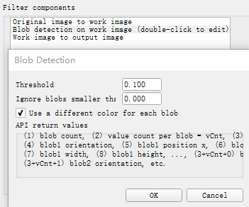
调用simReadVisionSensor来获取连通域信息,Packet2中将包含如下数据:
Packet2 = {blob count, dataSizePerBlob, blob1 size, blob1 orientation, blob1 position x, blob1 position y, blob1 width, blob1 height, blob2 size,blob2 orientation, blob2 position x, blob2 position y, blob2 width, blob2 height,...}
在Tool→User settings中将"Hide console window"前面的勾去掉,打开控制台窗口(因为要使用print函数在控制台输出信息),在Child script中加入如下代码:


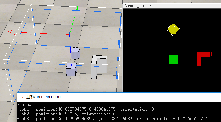
if (sim_call_type==sim_childscriptcall_initialization) then

    -- Put some initialization code here

    sensor = simGetObjectHandle("Vision_sensor")

end


if (sim_call_type==sim_childscriptcall_actuation) then

end


if (sim_call_type==sim_childscriptcall_sensing) then

    -- Put your main SENSING code here
    result, t0, t1 = simReadVisionSensor(sensor)
    if (t1) then -- in t1 we should have the blob information if the camera was set-up correctly
        blobCount=t1[1]
        dataSizePerBlob=t1[2]
        print(tostring(blobCount).."bolobs")

        -- Now we go through all blobs:
        for i=1,blobCount,1 do
            blobSize=t1[2+(i-1)*dataSizePerBlob+1]
            blobOrientation=t1[2+(i-1)*dataSizePerBlob+2] --This value is given in radians and represents the relative orientation of the blob's bounding box
            blobPos={t1[2+(i-1)*dataSizePerBlob+3],t1[2+(i-1)*dataSizePerBlob+4]} --{position x, position y}
            blobBoxDimensions={t1[2+(i-1)*dataSizePerBlob+5],t1[2+(i-1)*dataSizePerBlob+6]} --{width, height}

            print("blob"..tostring(i)..":  position:{"..tostring(blobPos[1])..","..tostring(blobPos[2]).."} orientation:"..tostring(blobOrientation*180/math.pi))
        end
    end

end


if (sim_call_type==sim_childscriptcall_cleanup) then

end
参考:
