

1. 使用OpenCV进行标定
相机已经有很长一段历史了。但是,伴随着20世纪后期的廉价针孔照相机的问世,它们已经变成我们日常生活的一种常见的存在。不幸的是,这种廉价是由代价的:显著的变形。幸运的是,这些是常数而且使用标定和一些重绘我们可以矫正这个。而且,使用标定你还可以确定照相机的像素和真实世界的坐标单位毫米之间关系。
原理:
对于变形(镜头畸变),OpenCV考虑径向畸变和切向畸变。
对于径向畸变参数使用以下公式:

所以对于一个输入图像的旧像素点(x,y),它在输出图像的新像素点坐标将会是(xcorrected, ycorrected)。径向畸变的出现表示了“桶”或者“鱼眼”效果。
切向畸变出现是因为镜头不能和成像平面完美平行。它可以通过以下公式纠正:

所以我们可以有5个畸变参数。在OpenCV中是以一个1行5列的矩阵表示的:

现在对于单位转换我们使用以下公式:

这里w是使用的单映射坐标系统表示(而且w=Z)。未知的参数是fx和fy(相机焦距)和(cx, cy)是光学中心以像素坐标表示。如果对于两个轴一个通用的焦距是通过一个给定的a比率使用(通常为1),那么fy=fx*a,在上面的公式中我们将会有一个单个的焦距f。即fx=fy=f。这个包含4个参数的矩阵是指的相机矩阵。由于畸变协参是相同的无论相机分辨率是多少,所以这些畸变协参应该按照当前分辨率缩放,而非校正后的分辨率。
确定这两个矩阵的过程称为标定。这些参数的计算是通过基本的几何等式完成的。使用的等式形式取决于选择的标定物体。当前OpenCV支持三种类型的物体来进行标定:
- 传统的黑白棋盘板
- 对称的圆圈图案
- 不对称的圆圈图案
基本上,你需要使用你的相机拍摄这些图案,然后让OpenCV找到它们。每个找到的图案会产生一个新的等式。为了解决这些等式你需要至少一个预先设定数量的图案照片来形成一个良好适定等式系统(什么叫适定问题)。这个数量对于黑白棋盘板要较高,而对于圆圈图案则较少。举例,理论上棋盘图案需要至少两个照片。然而,实际上我们的输入图像有相当数量的噪声,所以为了得到好的结果你可能需要至少从不同角度的10个好的输入图案照片。
目标:
样本应用将:
- 决定畸变矩阵
- 决定相机矩阵
- 从相机,视频和图片文件列中获取输入文件
- 文件中读取配置
- 保存结果到XML/YAML文件
- 计算重投影误差
源码:
You may also find the source code in the samples/cpp/tutorial_code/calib3d/camera_calibration/ folder of the OpenCV source library or download itfrom here.
你可以在OpenCV的源码库的samples/cpp/tutorial_code/calib3d/camera_calibration/文件夹中找到源码或者可以从这里下载。

The program has a single argument: the name of its configuration file. If none is given then it will try to open the one named “default.xml”. Here's a sample configuration file in XML format.
这个程序有一个单个参数:配置文件名称。如果没有给定那么它就会试着打开一个命名为“default.xml”的文件。这里是一个XML格式的样本配置文件。
In the configuration file you may choose to use camera as an input, a video file or an image list. If you opt for the last one, you will need to create a configuration file where you enumerate the images to use. Here’s an example of this. The important part to remember is that the images need to be specified using the absolute path or the relative one from your application’s working directory. You may find all this in the samples directory mentioned above.
在配置文件中你可以选择使用相机作为输入,或者是一个视频文件或者一个图片列表。如果你选择最后一个,你将需要创建一个配置文件,里面你列举要使用的图片。这里是一个样本文件。需要记住的重要部分是需要使用绝对路径指定或你的应用的工作路径的相对路径指定的图片。你可能在上面提到的样例路径中找到这些。
The application starts up with reading the settings from the configuration file. Although, this is an important part of it, it has nothing to do with the subject of this tutorial: camera calibration. Therefore, I’ve chosen not to post the code for that part here. Technical background on how to do this you can find in the File Input and Output using XML and YAML files tutorial.
这个应用以读取配置文件的设置启动。虽然读取配置文件是一个重要部分,但是它和本教程的主题无关:相机标定。所以,我选择不在这里贴这部分的源代码了。如果读取配置文件的技术背景资料你可以在“使用XML和YAML文件的文件读取和输出”教程中找到。
解释:
1. 读取设置
2.    Settings s;
3.    const string inputSettingsFile = argc > 1 ? argv[1] : "default.xml";
4.    FileStorage fs(inputSettingsFile, FileStorage::READ); // Read the settings
5.    if (!fs.isOpened())
6.    {
7.          cout << "Could not open the configuration file: \"" << inputSettingsFile << "\"" << endl;
8.          return -1;
9.    }
10.    fs["Settings"] >> s;
11.    fs.release();                                         // close Settings file
12.
13.    if (!s.goodInput)
14.    {
15.          cout << "Invalid input detected. Application stopping. " << endl;
16.          return -1;
17.    }
Settings为设置类。
For this I’ve used simple OpenCV class input operation. After reading the file I’ve an additional post-processing function that checks validity of the input. Only if all inputs are good then goodInput variable will be true.
对此,我使用简单的OpenCV类输入操作。在读取文件之后我有一个多余的处理之后的函数检查输入的有效性。只有在所有的输入都有效goodInput变量才为真。
Get next input, if it fails or we have enough of them - calibrate. After this we have a big loop where we do the following operations: get the next image from the image list, camera or video file. If this fails or we have enough images then we run the calibration process. In case of image we step out of the loop and otherwise the remaining frames will be undistorted (if the option is set) via changing from DETECTION mode to the CALIBRATED one.
获取下一个输入,如果失败了或者我们有足够的它们——标定。在这之后我们有一个大的循环,其中我们做以下的操作:从图片列表、相机或者视频文件中获取下一个图片。如果这个失败了或者我们有足够的图片那么我们进行标定的进程。在图片的情况下,通过从DETECTION模式转变到CALIBRATED模式我们跳出循环,否则剩余的帧将非失真的(如果这个选项设置了)。
19.    for(int i = 0;;++i)
20.    {
21.      Mat view;
22.      bool blinkOutput = false;
23.
24.      view = s.nextImage();
25.
26.      //-----  If no more image, or got enough, then stop calibration and show result -------------
27.      if( mode == CAPTURING && imagePoints.size() >= (unsigned)s.nrFrames )
28.      {
29.            if( runCalibrationAndSave(s, imageSize,  cameraMatrix, distCoeffs, imagePoints))
30.                  mode = CALIBRATED;
31.            else
32.                  mode = DETECTION;
33.      }
34.      if(view.empty())          // If no more images then run calibration, save and stop loop.
35.      {
36.                if( imagePoints.size() > 0 )
37.                      runCalibrationAndSave(s, imageSize,  cameraMatrix, distCoeffs, imagePoints);
38.                break;
39.      imageSize = view.size();  // Format input image.
40.      if( s.flipVertical )    flip( view, view, 0 );
41.      }
For some cameras we may need to flip the input image. Here we do this too.
对于一些相机我们可能需要跳过输入图片。这里我们也这么做。
Find the pattern in the current input. The formation of the equations I mentioned above aims to finding major patterns in the input: in case of the chessboard this are corners of the squares and for the circles, well, the circles themselves. The position of these will form the result which will be written into the pointBuf vector.
在当前输入中寻找图案。上面我提到的等式形式主要是为了查找输入中的主要图案:在棋盘模式下是方形的角,而对于圆形,好吧,是圆自己。这些的位置将形成结果保存到pintBuf矢量对象中。
43.    vector<Point2f> pointBuf;
44.
45.    bool found;
46.    switch( s.calibrationPattern ) // Find feature points on the input format
47.    {
48.    case Settings::CHESSBOARD:
49.      found = findChessboardCorners( view, s.boardSize, pointBuf,
50.      CV_CALIB_CB_ADAPTIVE_THRESH | CV_CALIB_CB_FAST_CHECK | CV_CALIB_CB_NORMALIZE_IMAGE);
51.      break;
52.    case Settings::CIRCLES_GRID:
53.      found = findCirclesGrid( view, s.boardSize, pointBuf );
54.      break;
55.    case Settings::ASYMMETRIC_CIRCLES_GRID:
56.      found = findCirclesGrid( view, s.boardSize, pointBuf, CALIB_CB_ASYMMETRIC_GRID );
57.      break;
58.    }
Depending on the type of the input pattern you use either the findChessboardCorners or the findCirclesGrid function. For both of them you pass the current image and the size of the board and you’ll get the positions of the patterns. Furthermore, they return a boolean variable which states if the pattern was found in the input (we only need to take into account those images where this is true!).
根据输入图案的类型你可以使用findChessboardCorners函数或者findCirclesGrid函数。对于两者你传入当前图像和板子的尺寸然后你将会得到图案的位置。而且,它们将会返回一个布尔类型表示是否图案已经在输入图像中找到了(我们只需要考虑为true的图片)。
Then again in case of cameras we only take camera images when an input delay time is passed. This is done in order to allow user moving the chessboard around and getting different images. Similar images result in similar equations, and similar equations at the calibration step will form an ill-posed problem, so the calibration will fail. For square images the positions of the corners are only approximate. We may improve this by calling the cornerSubPix function. It will produce better calibration result. After this we add a valid inputs result to the imagePoints vector to collect all of the equations into a single container. Finally, for visualization feedback purposes we will draw the found points on the input image using findChessboardCorners function.
然后再一次在相机模式下我们只需要每隔一个时间获取相机图像。这么做是为了允许用户移动棋盘然后得到不同角度的图像。相似的图像将导致相似的等式,而相似的等式在标定步骤时将产生一个病态不适定问题,然后标定将会失败。对于矩形图像拐角的位置是唯一有效的。我们可以通过调用cornerSubPix函数来提高这个效果。这将会产生更好的标定效果。在这之后我们添加一个有效的输入结果到imagePoints矢量中从而收集所有的等式到一个单个容器中。最后,对于视觉反馈目的我们将使用findChessboardCorners函数在输入图像中绘制找到的点。
 1 if ( found)                // If done with success,
 2   {
 3       // improve the found corners' coordinate accuracy for chessboard
 4         if( s.calibrationPattern == Settings::CHESSBOARD)
 5         {
 6             Mat viewGray;
 7             cvtColor(view, viewGray, CV_BGR2GRAY);
 8             cornerSubPix( viewGray, pointBuf, Size(11,11),
 9               Size(-1,-1), TermCriteria( CV_TERMCRIT_EPS+CV_TERMCRIT_ITER, 30, 0.1 ));
10         }
11
12         if( mode == CAPTURING &&  // For camera only take new samples after delay time
13             (!s.inputCapture.isOpened() || clock() - prevTimestamp > s.delay*1e-3*CLOCKS_PER_SEC) )
14         {
15             imagePoints.push_back(pointBuf);
16             prevTimestamp = clock();
17             blinkOutput = s.inputCapture.isOpened();
18         }
19
20         // Draw the corners.
21         drawChessboardCorners( view, s.boardSize, Mat(pointBuf), found );
22   }
Show state and result to the user, plus command line control of the application. This part shows text output on the image.
显示状态和结果给用户,以及应用的命令行控制。这部分将展示图像上的文本输出。
60.    //----------------------------- Output Text ------------------------------------------------
61.    string msg = (mode == CAPTURING) ? "100/100" :
62.              mode == CALIBRATED ? "Calibrated" : "Press 'g' to start";
63.    int baseLine = 0;
64.    Size textSize = getTextSize(msg, 1, 1, 1, &baseLine);
65.    Point textOrigin(view.cols - 2*textSize.width - 10, view.rows - 2*baseLine - 10);
66.
67.    if( mode == CAPTURING )
68.    {
69.      if(s.showUndistorsed)
70.        msg = format( "%d/%d Undist", (int)imagePoints.size(), s.nrFrames );
71.      else
72.        msg = format( "%d/%d", (int)imagePoints.size(), s.nrFrames );
73.    }
74.
75.    putText( view, msg, textOrigin, 1, 1, mode == CALIBRATED ?  GREEN : RED);
76.
77.    if( blinkOutput )
78.       bitwise_not(view, view);
If we ran calibration and got camera’s matrix with the distortion coefficients we may want to correct the image using undistort function:
如果我们运行标定然后得到带有畸变协参的相机的矩阵,我们可能希望使用undistort函数纠正图像。
1 //------------------------- Video capture  output  undistorted ------------------------------
2 if( mode == CALIBRATED && s.showUndistorsed )
3 {
4   Mat temp = view.clone();
5   undistort(temp, view, cameraMatrix, distCoeffs);
6 }
7 //------------------------------ Show image and check for input commands -------------------
8 imshow("Image View", view);
Then we wait for an input key and if this is u we toggle the distortion removal, if it is g we start again the detection process, and finally for the ESC key we quit the application:
然后我们等待一个输入键,如果是u的话我们切换失真移除,如果是g的话我们重新启动检测步骤,最后等待ESC键退出程序:
 1 char key =  waitKey(s.inputCapture.isOpened() ? 50 : s.delay);
 2 if( key  == ESC_KEY )
 3       break;
 4
 5 if( key == 'u' && mode == CALIBRATED )
 6    s.showUndistorsed = !s.showUndistorsed;
 7
 8 if( s.inputCapture.isOpened() && key == 'g' )
 9 {
10   mode = CAPTURING;
11   imagePoints.clear();
12 }
Show the distortion removal for the images too. When you work with an image list it is not possible to remove the distortion inside the loop. Therefore, you must do this after the loop. Taking advantage of this now I’ll expand the undistort function, which is in fact first calls initUndistortRectifyMap to find transformation matrices and then performs transformation using remap function. Because, after successful calibration map calculation needs to be done only once, by using this expanded form you may speed up your application:
显示图像的失真移除。当你采用一个图片列进行工作的时候,不可能在循环内部移除失真。因此,你必须在循环之后做这个。考虑到这个现在我将拓展undistort函数,它实际上首先调用initUndistortRectifyMap来查找转换矩阵,然后使用remap函数执行转换。因为,在成功标定之后,地图计算需要一次执行完,通过使用这种延展的方式你可能会加快你的程序:
80.    if( s.inputType == Settings::IMAGE_LIST && s.showUndistorsed )
81.    {
82.      Mat view, rview, map1, map2;
83.      initUndistortRectifyMap(cameraMatrix, distCoeffs, Mat(),
84.          getOptimalNewCameraMatrix(cameraMatrix, distCoeffs, imageSize, 1, imageSize, 0),
85.          imageSize, CV_16SC2, map1, map2);
86.
87.      for(int i = 0; i < (int)s.imageList.size(); i++ )
88.      {
89.          view = imread(s.imageList[i], 1);
90.          if(view.empty())
91.              continue;
92.          remap(view, rview, map1, map2, INTER_LINEAR);
93.          imshow("Image View", rview);
94.          char c = waitKey();
95.          if( c  == ESC_KEY || c == 'q' || c == 'Q' )
96.              break;
97.      }
98.    }
标定与保存:
Because the calibration needs to be done only once per camera, it makes sense to save it after a successful calibration. This way later on you can just load these values into your program. Due to this we first make the calibration, and if it succeeds we save the result into an OpenCV style XML or YAML file, depending on the extension you give in the configuration file.
因为标定需要每个相机只做一次就够了。所以有必要在成功标定后将参数保存下来。这样以后你就能直接加载这些参数到你的项目中了。由于这个原因我们首先进行标定,然后如果成功了我们将保存结果到一个OpenCV格式的XML或YAML文件中,这取决于你给的配置文件的拓展名。
Therefore in the first function we just split up these two processes. Because we want to save many of the calibration variables we’ll create these variables here and pass on both of them to the calibration and saving function. Again, I’ll not show the saving part as that has little in common with the calibration. Explore the source file in order to find out how and what:
因此在第一个函数中我们只需要分开两个步骤。因为我们想保存这些标定参数我们将在这里创建这些参数,然后同时将它们传递给标定和保存函数中。再次,我将不会展示保存的部分,因为那跟标定关系不大。自己探索源代码文件查看如何以及怎样保存的:
 1 bool runCalibrationAndSave(Settings& s, Size imageSize, Mat&  cameraMatrix, Mat& distCoeffs,vector<vector<Point2f> > imagePoints )
 2 {
 3  vector<Mat> rvecs, tvecs;
 4  vector<float> reprojErrs;
 5  double totalAvgErr = 0;
 6
 7  bool ok = runCalibration(s,imageSize, cameraMatrix, distCoeffs, imagePoints, rvecs, tvecs,
 8                           reprojErrs, totalAvgErr);
 9  cout << (ok ? "Calibration succeeded" : "Calibration failed")
10      << ". avg re projection error = "  << totalAvgErr ;
11
12  if( ok )   // save only if the calibration was done with success
13      saveCameraParams( s, imageSize, cameraMatrix, distCoeffs, rvecs ,tvecs, reprojErrs,
14                          imagePoints, totalAvgErr);
15  return ok;
16 }
We do the calibration with the help of the calibrateCamera function. It has the following parameters:
我们将在calibrateCamera的函数帮助下做标定。它有如下参数:
- The object points. This is a vector of Point3f vector that for each input image describes how should the pattern look. If we have a planar pattern (like a chessboard) then we can simply set all Z coordinates to zero. This is a collection of the points where these important points are present. Because, we use a single pattern for all the input images we can calculate this just once and multiply it for all the other input views. We calculate the corner points with the calcBoardCornerPositions function as:
对象点。这是一个为每个输入图片所创建的Point3f矢量的对象,它描述了图案的长相。如果我们有一个平面的图像(比如一个棋盘)那么我们能够简单地设置所有的Z坐标为0。这是一个显示重要点的点的集合。因为,我们为所有的输入图像使用一个单个的图案,我们可以计算一次然后将它乘以其他的输入图像矩阵。我们使用calcBoardCornerPositions函数计算这些拐角点:
void calcBoardCornerPositions(Size boardSize, float squareSize, vector<Point3f>& corners, Settings::Pattern patternType /*= Settings::CHESSBOARD*/) { corners.clear(); switch(patternType) { case Settings::CHESSBOARD: case Settings::CIRCLES_GRID: for( int i = 0; i < boardSize.height; ++i ) for( int j = 0; j < boardSize.width; ++j ) corners.push_back(Point3f(float( j*squareSize ), float( i*squareSize ), 0)); break; case Settings::ASYMMETRIC_CIRCLES_GRID: for( int i = 0; i < boardSize.height; i++ ) for( int j = 0; j < boardSize.width; j++ ) corners.push_back(Point3f(float((2*j + i % 2)*squareSize), float(i*squareSize), 0)); break; } }
And then multiply it as:
然后如下将它相乘:
vector<vector<Point3f> > objectPoints(1);
calcBoardCornerPositions(s.boardSize, s.squareSize, objectPoints[0], s.calibrationPattern);
objectPoints.resize(imagePoints.size(),objectPoints[0]);
- The image points. This is a vector of Point2f vector which for each input image contains coordinates of the important points (corners for chessboard and centers of the circles for the circle pattern). We have already collected this from findChessboardCorners or findCirclesGrid function. We just need to pass it on.
图像点。这是一个Point2f矢量的矢量对象,它对每个输入图像来说都包含重要的点坐标(棋盘板的拐角,以及圆图案的圆心)。我们已经通过findChessboardCorners函数或者findCirclesGrid函数收集了这个。我们只需要传递过来。
- The size of the image acquired from the camera, video file or the images.
从相机、视频文件或者图片中获取的图像的尺寸。
- The camera matrix. If we used the fixed aspect ratio option we need to set the fx to zero:
相机矩阵。如果我们使用修正后的长宽比率选项我们需要将fx设置为0:
cameraMatrix = Mat::eye(3, 3, CV_64F); if( s.flag & CV_CALIB_FIX_ASPECT_RATIO ) cameraMatrix.at<double>(0,0) = 1.0;
The distortion coefficient matrix. Initialize with zero.畸变协矩阵。初始化为0。
distCoeffs = Mat::zeros(8, 1, CV_64F);
For all the views the function will calculate rotation and translation vectors which transform the object points (given in the model coordinate space) to the image points (given in the world coordinate space). The 7-th and 8-th parameters are the output vector of matrices containing in the i-th position the rotation and translation vector for the i-th object point to the i-th image point.
对于所有的图像矩阵该函数将计算旋转和平移矢量,它们将对象点(在模型坐标系中给出)转换到图像点(在世界坐标系中)上。 第7和第8参数是包含在第i位置的从第i对象到第i图像点的旋转和平移向量矩阵的输出向量。
- The final argument is the flag. You need to specify here options like fix the aspect ratio for the focal length, assume zero tangential distortion or to fix the principal point.
最后的参数是标志。你需要指定选项像修正焦距的长宽比率,假定零正切失真或者修正法线点。
double rms = calibrateCamera(objectPoints, imagePoints, imageSize, cameraMatrix,
                            distCoeffs, rvecs, tvecs, s.flag|CV_CALIB_FIX_K4|CV_CALIB_FIX_K5);
- The function returns the average re-projection error. This number gives a good estimation of precision of the found parameters. This should be as close to zero as possible. Given the intrinsic, distortion, rotation and translation matrices we may calculate the error for one view by using the projectPoints to first transform the object point to image point. Then we calculate the absolute norm between what we got with our transformation and the corner/circle finding algorithm. To find the average error we calculate the arithmetical mean of the errors calculated for all the calibration images.
该函数返回平均重映射误差。 这个数给出一个找到的参数的精度的好的预测。这个应该尽可能接近于0。考虑到内在的,失真,旋转和平移矩阵我们可以通过使用projectPoints将对象点转换到图像点来计算每个图片的误差。然后我们计算我们转换得到的与使用查找算法得到拐角/圆圈之间的绝对的二范数。为了得到平均误差我们为所有的标定图像计算算术平均误差。
double computeReprojectionErrors( const vector<vector<Point3f> >& objectPoints, const vector<vector<Point2f> >& imagePoints, const vector<Mat>& rvecs, const vector<Mat>& tvecs, const Mat& cameraMatrix , const Mat& distCoeffs, vector<float>& perViewErrors) { vector<Point2f> imagePoints2; int i, totalPoints = 0; double totalErr = 0, err; perViewErrors.resize(objectPoints.size()); for( i = 0; i < (int)objectPoints.size(); ++i ) { projectPoints( Mat(objectPoints[i]), rvecs[i], tvecs[i], cameraMatrix, // project distCoeffs, imagePoints2); err = norm(Mat(imagePoints[i]), Mat(imagePoints2), CV_L2); // difference int n = (int)objectPoints[i].size(); perViewErrors[i] = (float) std::sqrt(err*err/n); // save for this view totalErr += err*err; // sum it up totalPoints += n; } return std::sqrt(totalErr/totalPoints); // calculate the arithmetical mean }
图像:
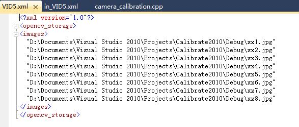
Let there be this input chessboard pattern which has a size of 9 X 6. I’ve used an AXIS IP camera to create a couple of snapshots of the board and saved it into VID5 directory. I’ve put this inside the images/CameraCalibration folder of my working directory and created the following VID5.XML file that describes which images to use:
让尺寸为9x6的棋盘图案做输入。 我使用了一个AXIS IP相机来拍摄了几个照片然后保存到VID5路径。我已经将这个放到我工作目录的images/CameraCalibration文件夹,然后创建了接下来的的VID5.XML文件,描述了使用的哪些图片:
<?xml version="1.0"?>
<opencv_storage>
<images>
images/CameraCalibration/VID5/xx1.jpg
images/CameraCalibration/VID5/xx2.jpg
images/CameraCalibration/VID5/xx3.jpg
images/CameraCalibration/VID5/xx4.jpg
images/CameraCalibration/VID5/xx5.jpg
images/CameraCalibration/VID5/xx6.jpg
images/CameraCalibration/VID5/xx7.jpg
images/CameraCalibration/VID5/xx8.jpg
</images>
</opencv_storage>
Then passed images/CameraCalibration/VID5/VID5.XML as an input in the configuration file. Here’s a chessboard pattern found during the runtime of the application:
然后传递images/CameraCalibration/VID5/VID5.XML作为一个配置文件的输入值。这里是一个在程序运行时查找到的棋盘板图案。

After applying the distortion removal we get:执行完失真移除之后我们得到:

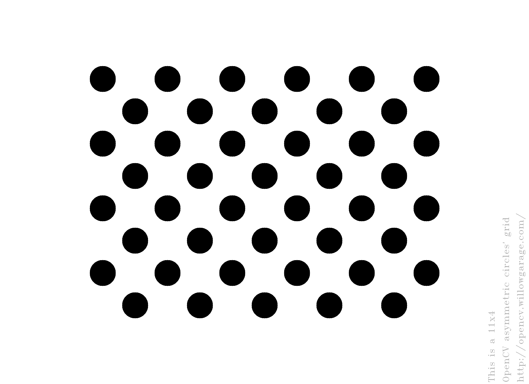
The same works for this asymmetrical circle pattern by setting the input width to 4 and height to 11. This time I’ve used a live camera feed by specifying its ID (“1”) for the input. Here’s, how a detected pattern should look:
同样可以使用这种非对称的圆图案设置输入宽度为4、输入高度为11。这一次我使用了一个现场直播摄像头反馈,通过指定ID(“1”)作为输入。这里,检测到的图案应该是看起来这样:

In both cases in the specified output XML/YAML file you’ll find the camera and distortion coefficients matrices:
在这两种情况下在指定的输出XML/YAML文件中你将会找到摄像头和失真协参矩阵:
<Camera_Matrix type_id="opencv-matrix">
<rows>3</rows>
<cols>3</cols>
<dt>d</dt>
<data>
 6.5746697944293521e+002 0. 3.1950000000000000e+002 0.
 6.5746697944293521e+002 2.3950000000000000e+002 0. 0. 1.</data></Camera_Matrix>
<Distortion_Coefficients type_id="opencv-matrix">
<rows>5</rows>
<cols>1</cols>
<dt>d</dt>
<data>
 -4.1802327176423804e-001 5.0715244063187526e-001 0. 0.
 -5.7843597214487474e-001</data></Distortion_Coefficients>
Add these values as constants to your program, call the initUndistortRectifyMap and the remap function to remove distortion and enjoy distortion free inputs for cheap and low quality cameras.
将这些值作为常数添加到你的程序中,调用initUndistortRectifyMap和remap函数来移除失真,然后享受来自廉价和低清晰摄像头的没有畸变的输入吧。
>>OpenCV做相机标定原文链接
http://docs.opencv.org/2.4/doc/tutorials/calib3d/camera_calibration/camera_calibration.html
终于成功了,注意事项:
如果VS2008不行,就试一试VS2010,因为需要跟你的编译库相对应。如果Debug不行,就试试Release。总之,多试几次。
详细指导教程:

文件放在Debug文件夹下:

其中in_VID5.xml是输入参数:
 BoardSize_Width为内角点的宽方向的个数,BoardSize_Height为内角点的高方向的个数。Square_Size为用户定义的坐标系下的一个四方格的尺寸(一般设为真实尺寸的多少mm)。
VID5.xml为图片索引
最后的输出结果:

共6帧图像,宽7个角点,高7个角点,正方形尺寸40,修正宽高比率1,相机矩阵,畸变协阵,平均重投影误差。
可以看到fx=4.85*10^2, cx=3.195*10^2, fy=4.85*10^2, cy=1.795*10^2,
K1=-1.964*10^(-2), K2=-1.45*10^(-1), K3=4.856*10^(-1)
以上是采用3.1自带的程序实验的。也可以参考OpenCV2.46版:opencv标定程序(修改),但在OpenCV3.1上实验会有内存错误。
》》扩展阅读
1. 软件《多基线近景摄影测量软件》 相机检校 X:出现“无效相片”
2. 软件《Photomodeler Scanner》 camera calibrate
3. C++ 摄影测量 依赖于OpenCV
依赖库:
opengl32.lib
glu32.lib
glaux.lib
cximagecrtd.lib
cv.lib
highgui.lib
cxcore.lib
BLASd.lib
clapackd.lib
libf2cd.lib
tmglibd.lib
libumfpack.lib
libamd.lib
界面设计:(MFC界面库)

1.新建工程,选择添加文件
 取名为“H”,将在D盘新建一个名为H的文件夹工程,

 选择默认的图像组[0],点确定,将加载图像组

可见图像组是由0-7八个标定图和0-25二十六个拍摄图总共34个组成。
 点击标记圆检测
即完成标记圆检测,标记圆是自己制作的标定物
标定成功后,可以看到每个图像的标定圆以红色十字架标记,第二列数字表示每张图像中的标记圆个数,可见有的标记圆没有被正确标记出

然后点击摄像机标定,求取摄像机的内外方位元素

然后点击“多视图重构”按钮,出现了错误
4. Halcon
张正友的《相机标定法》
5. Matlab
问题1:初始值需不需要设置
相机迭代参数初始值不需要设置
附加依赖项:
opencv_calib3d310d.lib
opencv_core310d.lib
opencv_features2d310d.lib
opencv_flann310d.lib
opencv_highgui310d.lib
opencv_imgcodecs310d.lib
opencv_imgproc310d.lib
opencv_ml310d.lib
opencv_objdetect310d.lib
opencv_photo310d.lib
opencv_shape310d.lib
opencv_stitching310d.lib
opencv_superres310d.lib
opencv_ts310d.lib
opencv_video310d.lib
opencv_videoio310d.lib
opencv_videostab310d.lib
完整引用
opencv_calib3d310d.lib
opencv_core310d.lib
opencv_features2d310d.lib
opencv_flann310d.lib
opencv_highgui310d.lib
opencv_imgcodecs310d.lib
opencv_imgproc310d.lib
opencv_ml310d.lib
opencv_objdetect310d.lib
opencv_photo310d.lib
opencv_shape310d.lib
opencv_stitching310d.lib
opencv_superres310d.lib
opencv_ts310d.lib
opencv_video310d.lib
opencv_videoio310d.lib
opencv_videostab310d.lib
pcl_kdtree_debug.lib
pcl_io_debug.lib
pcl_search_debug.lib
pcl_segmentation_debug.lib
pcl_apps_debug.lib
pcl_features_debug.lib
pcl_filters_debug.lib
pcl_visualization_debug.lib
pcl_common_debug.lib
pcl_kdtree_release.lib
pcl_io_release.lib
pcl_search_release.lib
pcl_segmentation_release.lib
pcl_apps_release.lib
pcl_features_release.lib
pcl_filters_release.lib
pcl_visualization_release.lib
pcl_common_release.lib
flann_cpp_s-gd.lib
boost_date_time-vc100-mt-1_49.lib
boost_date_time-vc100-mt-gd-1_49.lib
boost_filesystem-vc100-mt-1_49.lib
boost_filesystem-vc100-mt-gd-1_49.lib
boost_iostreams-vc100-mt-1_49.lib
boost_iostreams-vc100-mt-gd-1_49.lib
boost_serialization-vc100-mt-1_49.lib
boost_serialization-vc100-mt-gd-1_49.lib
boost_system-vc100-mt-1_49.lib
boost_system-vc100-mt-gd-1_49.lib
boost_thread-vc100-mt-1_49.lib
boost_thread-vc100-mt-gd-1_49.lib
boost_wserialization-vc100-mt-1_49.lib
boost_wserialization-vc100-mt-gd-1_49.lib
libboost_date_time-vc100-mt-1_49.lib
libboost_date_time-vc100-mt-gd-1_49.lib
libboost_filesystem-vc100-mt-1_49.lib
libboost_filesystem-vc100-mt-gd-1_49.lib
libboost_iostreams-vc100-mt-1_49.lib
libboost_iostreams-vc100-mt-gd-1_49.lib
libboost_serialization-vc100-mt-1_49.lib
libboost_serialization-vc100-mt-gd-1_49.lib
libboost_system-vc100-mt-1_49.lib
libboost_system-vc100-mt-gd-1_49.lib
libboost_thread-vc100-mt-1_49.lib
libboost_thread-vc100-mt-gd-1_49.lib
libboost_wserialization-vc100-mt-1_49.lib
libboost_wserialization-vc100-mt-gd-1_49.lib
openNI.lib
OpenNI.jni.lib
NiSampleModule.lib
NiSampleExtensionModule.lib
vtkalglib-gd.lib
vtkCharts-gd.lib
vtkCommon-gd.lib
vtkDICOMParser-gd.lib
vtkexoIIc-gd.lib
vtkexpat-gd.lib
vtkFiltering-gd.lib
vtkfreetype-gd.lib
vtkftgl-gd.lib
vtkGenericFiltering-gd.lib
vtkGeovis-gd.lib
vtkGraphics-gd.lib
vtkhdf5-gd.lib
vtkHybrid-gd.lib
vtkImaging-gd.lib
vtkInfovis-gd.lib
vtkIO-gd.lib
vtkjpeg-gd.lib
vtklibxml2-gd.lib
vtkmetaio-gd.lib
vtkNetCDF-gd.lib
vtkNetCDF_cxx-gd.lib
vtkpng-gd.lib
vtkproj4-gd.lib
vtkRendering-gd.lib
vtksqlite-gd.lib
vtksys-gd.lib
vtktiff-gd.lib
vtkverdict-gd.lib
vtkViews-gd.lib
vtkVolumeRendering-gd.lib
vtkWidgets-gd.lib
vtkzlib-gd.lib
Executable Directories:
E:\QQDownload\PCL1_6\PCL 1.6.0\bin;E:\opencv_c\install\x86\vc10\bin;E:\QQDownload\PCL1_6\PCL 1.6.0\3rdParty\VTK\bin;E:\QQDownload\PCL1_6\PCL 1.6.0\3rdParty\Qhull\bin;E:\QQDownload\OpenNI\Bin;E:\QQDownload\PCL1_6\PCL 1.6.0\3rdParty\FLANN\bin;E:\QQDownload\PCL1_6\PCL 1.6.0\3rdParty\Eigen\bin;$(ExecutablePath)
Include Directories:
E:\QQDownload\PCL1_6\PCL 1.6.0\3rdParty\VTK\include\vtk-5.8;E:\QQDownload\PCL1_6\PCL 1.6.0\3rdParty\Qhull\include;E:\QQDownload\OpenNI\Include;E:\QQDownload\PCL1_6\PCL 1.6.0\3rdParty\FLANN\include;E:\QQDownload\PCL1_6\PCL 1.6.0\3rdParty\Eigen\include;E:\QQDownload\PCL1_6\PCL 1.6.0\3rdParty\Boost\include;E:\QQDownload\PCL1_6\PCL 1.6.0\include\pcl-1.6;E:\opencv_c\install\include;$(IncludePath)
Library Directories:
E:\QQDownload\OpenNI\Lib;E:\QQDownload\PCL1_6\PCL 1.6.0\3rdParty\VTK\lib\vtk-5.8;E:\QQDownload\PCL1_6\PCL 1.6.0\3rdParty\Qhull\lib;E:\QQDownload\PCL1_6\PCL 1.6.0\3rdParty\FLANN\lib;E:\QQDownload\PCL1_6\PCL 1.6.0\3rdParty\Boost\lib;E:\QQDownload\PCL1_6\PCL 1.6.0\lib;E:\opencv_c\install\x86\vc10\staticlib;E:\opencv_c\install\x86\vc10\lib;$(LibraryPath)
VS2010,Release模式,添加了OpenNI,OpenCV,VTK,Boost,PCL...均为2010编译器编译的,32位。选的Release执行成功。
g2o
g2o_cli.lib
g2o_core.lib
g2o_csparse_extension.lib
g2o_ext_csparse.lib
g2o_ext_freeglut_minimal.lib
g2o_interface.lib
g2o_opengl_helper.lib
g2o_parser.lib
g2o_simulator.lib
g2o_solver_csparse.lib
g2o_solver_dense.lib
g2o_solver_pcg.lib
g2o_solver_slam2d_linear.lib
g2o_solver_structure_only.lib
g2o_stuff.lib
g2o_types_data.lib
g2o_types_icp.lib
g2o_types_sba.lib
g2o_types_sclam2d.lib
g2o_types_sim3.lib
g2o_types_slam2d.lib
g2o_types_slam2d_addons.lib
g2o_types_slam3d.lib
g2o_types_slam3d_addons.lib
g2o_viewer.lib

 浙公网安备 33010602011771号