
[蓝牙] 5、Battery Service module
Detailed Description
This module implements the Battery Service with the Battery Level characteristic. During initialization it adds the Battery Service and Battery Level characteristic to the BLE stack database. Optionally随意地 it can also add a Report Reference descriptor to the Battery Level characteristic (used when including the Battery Service in the HID service).
If specified, the module will support notification of the Battery Level characteristic through the ble_bas_battery_level_update() function. If an event handler is supplied by the application, the Battery Service will generate Battery Service events to the application.
- Note
- The application must propagate BLE stack events to the Battery Service module by calling ble_bas_on_ble_evt() from the from the ble_stack_handler callback.
- Attention! To maintain compliance with Nordic Semiconductor ASA Bluetooth profile qualification listings, this section of source code must not be modified.
注:
这个电量服务和心率有点类似,通过定时器产生一个周期性的timeout回调函数battery_level_meas_timeout_handler,在其中调用battery_start()实现making the ADC start a battery level conversion。
概述:
In addition, the use of the ADC to measure the battery level is also demonstrated论证.
When the application starts, two timers are started which control when the heart rate value and battery level should be sent
Battery level measurement:
When the peer has enabled notification for Battery Level, the application begins sending the battery level as notifications.
Note that the measurement is made every 2 seconds. But as per the Battery Service Specification, the notification of battery level will be sent only if the it has changed.
The ADC is used to measure the battery level. Every time a new battery measurement has to be sent, a fresh measurement is made.
- Note
- The application will stop advertising after 180 seconds and go to system-off mode. Push the button 0 or button 1 to restart advertising.
timers_init产生电量测量定时器
1     // Create timers
2     err_code = app_timer_create(&m_battery_timer_id,
3                                 APP_TIMER_MODE_REPEATED,
4                                 battery_level_meas_timeout_handler);
5     APP_ERROR_CHECK(err_code);
上面代码生成电量超时检测定时器,每隔一定时期触发battery_level_meas_timeout_handler:
 1 /**@brief Function for handling the Battery measurement timer timeout.
 2  *
 3  * @details This function will be called each time the battery level measurement timer expires.
 4  *          This function will start the ADC.
 5  *
 6  * @param[in]   p_context   Pointer used for passing some arbitrary information (context) from the
 7  *                          app_start_timer() call to the timeout handler.
 8  */
 9 static void battery_level_meas_timeout_handler(void * p_context)
10 {
11     UNUSED_PARAMETER(p_context);
12     battery_start();
13 }
其中第11行是一个类似于uc-os里面的东西~宏定义如下:
battery_start()电量测量的AD配置及使能ADC_IRQn外部中断
 1 /**@brief Function for making the ADC start a battery level conversion.
 2  */
 3 void battery_start(void)
 4 {
 5     uint32_t err_code;
 6
 7     // Configure ADC
 8     NRF_ADC->INTENSET   = ADC_INTENSET_END_Msk;
 9     NRF_ADC->CONFIG     = (ADC_CONFIG_RES_8bit                        << ADC_CONFIG_RES_Pos)     |//后一个是位置,前一个是设置,在下面讲解中在一起的
10                           (ADC_CONFIG_INPSEL_SupplyOneThirdPrescaling << ADC_CONFIG_INPSEL_Pos)  |
11                           (ADC_CONFIG_REFSEL_VBG                      << ADC_CONFIG_REFSEL_Pos)  |
12                           (ADC_CONFIG_PSEL_Disabled                   << ADC_CONFIG_PSEL_Pos)    |
13                           (ADC_CONFIG_EXTREFSEL_None                  << ADC_CONFIG_EXTREFSEL_Pos);
14     NRF_ADC->EVENTS_END = 0;
15     NRF_ADC->ENABLE     = ADC_ENABLE_ENABLE_Enabled;
16
17     // Enable ADC interrupt
18     err_code = sd_nvic_ClearPendingIRQ(ADC_IRQn);
19     APP_ERROR_CHECK(err_code);
20
21     err_code = sd_nvic_SetPriority(ADC_IRQn, NRF_APP_PRIORITY_LOW);
22     APP_ERROR_CHECK(err_code);
23
24     err_code = sd_nvic_EnableIRQ(ADC_IRQn);
25     APP_ERROR_CHECK(err_code);
26
27     NRF_ADC->EVENTS_END  = 0;    // Stop any running conversions.
28     NRF_ADC->TASKS_START = 1;
29 }
NRF_ADC的结构体为:
 1 typedef struct {                                    /*!< ADC Structure                                                         */
 2   __O  uint32_t  TASKS_START;                       /*!< Start an ADC conversion.                                              */
 3   __O  uint32_t  TASKS_STOP;                        /*!< Stop ADC.                                                             */
 4   __I  uint32_t  RESERVED0[62];
 5   __IO uint32_t  EVENTS_END;                        /*!< ADC conversion complete.                                              */
 6   __I  uint32_t  RESERVED1[128];
 7   __IO uint32_t  INTENSET;                          /*!< Interrupt enable set register.                                        */
 8   __IO uint32_t  INTENCLR;                          /*!< Interrupt enable clear register.                                      */
 9   __I  uint32_t  RESERVED2[61];
10   __I  uint32_t  BUSY;                              /*!< ADC busy register.                                                    */
11   __I  uint32_t  RESERVED3[63];
12   __IO uint32_t  ENABLE;                            /*!< ADC enable.                                                           */
13   __IO uint32_t  CONFIG;                            /*!< ADC configuration register.                                           */
14   __I  uint32_t  RESULT;                            /*!< Result of ADC conversion.                                             */
15   __I  uint32_t  RESERVED4[700];
16   __IO uint32_t  POWER;                             /*!< Peripheral power control.                                             */
17 } NRF_ADC_Type;
黄色部分AD中断使能的意义:
1 /* Register: ADC_INTENSET */
2 /* Description: Interrupt enable set register. */
3
4 /* Bit 0 : Enable interrupt on END event. */
5 #define ADC_INTENSET_END_Pos (0UL) /*!< Position of END field. */
6 #define ADC_INTENSET_END_Msk (0x1UL << ADC_INTENSET_END_Pos) /*!< Bit mask of END field. */
7 #define ADC_INTENSET_END_Disabled (0UL) /*!< Interrupt disabled. */
8 #define ADC_INTENSET_END_Enabled (1UL) /*!< Interrupt enabled. */
9 #define ADC_INTENSET_END_Set (1UL) /*!< Enable interrupt on write. */
绿色部分AD初始化的意义:
 1 /* Register: ADC_CONFIG */
 2 /* Description: ADC configuration register. */
 3
 4 /* Bits 17..16 : ADC external reference pin selection. */
 5 #define ADC_CONFIG_EXTREFSEL_Pos (16UL) /*!< Position of EXTREFSEL field. */
 6 #define ADC_CONFIG_EXTREFSEL_Msk (0x3UL << ADC_CONFIG_EXTREFSEL_Pos) /*!< Bit mask of EXTREFSEL field. */
 7 #define ADC_CONFIG_EXTREFSEL_None (0UL) /*!< Analog external reference inputs disabled. */
 8 #define ADC_CONFIG_EXTREFSEL_AnalogReference0 (1UL) /*!< Use analog reference 0 as reference. */
 9 #define ADC_CONFIG_EXTREFSEL_AnalogReference1 (2UL) /*!< Use analog reference 1 as reference. */
10
11 /* Bits 15..8 : ADC analog pin selection. */
12 #define ADC_CONFIG_PSEL_Pos (8UL) /*!< Position of PSEL field. */
13 #define ADC_CONFIG_PSEL_Msk (0xFFUL << ADC_CONFIG_PSEL_Pos) /*!< Bit mask of PSEL field. */
14 #define ADC_CONFIG_PSEL_Disabled (0UL) /*!< Analog input pins disabled. */
15 #define ADC_CONFIG_PSEL_AnalogInput0 (1UL) /*!< Use analog input 0 as analog input. */
16 #define ADC_CONFIG_PSEL_AnalogInput1 (2UL) /*!< Use analog input 1 as analog input. */
17 #define ADC_CONFIG_PSEL_AnalogInput2 (4UL) /*!< Use analog input 2 as analog input. */
18 #define ADC_CONFIG_PSEL_AnalogInput3 (8UL) /*!< Use analog input 3 as analog input. */
19 #define ADC_CONFIG_PSEL_AnalogInput4 (16UL) /*!< Use analog input 4 as analog input. */
20 #define ADC_CONFIG_PSEL_AnalogInput5 (32UL) /*!< Use analog input 5 as analog input. */
21 #define ADC_CONFIG_PSEL_AnalogInput6 (64UL) /*!< Use analog input 6 as analog input. */
22 #define ADC_CONFIG_PSEL_AnalogInput7 (128UL) /*!< Use analog input 7 as analog input. */
23
24 /* Bits 6..5 : ADC reference参照 selection. */
25 #define ADC_CONFIG_REFSEL_Pos (5UL) /*!< Position of REFSEL field. */
26 #define ADC_CONFIG_REFSEL_Msk (0x3UL << ADC_CONFIG_REFSEL_Pos) /*!< Bit mask of REFSEL field. */
27 #define ADC_CONFIG_REFSEL_VBG (0x00UL) /*!< Use internal 1.2V bandgap频带间隙 voltage as reference for conversion. */
28 #define ADC_CONFIG_REFSEL_External (0x01UL) /*!< Use external source configured by EXTREFSEL as reference for conversion. */
29 #define ADC_CONFIG_REFSEL_SupplyOneHalfPrescaling (0x02UL) /*!< Use supply voltage with 1/2 prescaling as reference for conversion. Only usable when supply voltage is between 1.7V and 2.6V. */
30 #define ADC_CONFIG_REFSEL_SupplyOneThirdPrescaling (0x03UL) /*!< Use supply voltage with 1/3 prescaling as reference for conversion. Only usable when supply voltage is between 2.5V and 3.6V. */
31
32 /* Bits 4..2 : ADC input selection. */
33 #define ADC_CONFIG_INPSEL_Pos (2UL) /*!< Position of INPSEL field. */
34 #define ADC_CONFIG_INPSEL_Msk (0x7UL << ADC_CONFIG_INPSEL_Pos) /*!< Bit mask of INPSEL field. */
35 #define ADC_CONFIG_INPSEL_AnalogInputNoPrescaling (0x00UL) /*!< Analog input specified by PSEL with no prescaling used as input for the conversion. */
36 #define ADC_CONFIG_INPSEL_AnalogInputTwoThirdsPrescaling (0x01UL) /*!< Analog input specified by PSEL with 2/3 prescaling used as input for the conversion. */
37 #define ADC_CONFIG_INPSEL_AnalogInputOneThirdPrescaling (0x02UL) /*!< Analog input specified by PSEL with 1/3 prescaling used as input for the conversion. */
38 #define ADC_CONFIG_INPSEL_SupplyTwoThirdsPrescaling (0x05UL) /*!< Supply voltage with 2/3 prescaling used as input for the conversion. */
39 #define ADC_CONFIG_INPSEL_SupplyOneThirdPrescaling (0x06UL) /*!< Supply voltage with 1/3 prescaling 预分频 used as input for the conversion. */
40
41 /* Bits 1..0 : ADC resolution. */
42 #define ADC_CONFIG_RES_Pos (0UL) /*!< Position of RES field. */
43 #define ADC_CONFIG_RES_Msk (0x3UL << ADC_CONFIG_RES_Pos) /*!< Bit mask of RES field. */
44 #define ADC_CONFIG_RES_8bit (0x00UL) /*!< 8bit ADC resolution分辨率. */
45 #define ADC_CONFIG_RES_9bit (0x01UL) /*!< 9bit ADC resolution. */
46 #define ADC_CONFIG_RES_10bit (0x02UL) /*!< 10bit ADC resolution. */
综上:AD的配置为——
44>8bit分辨率+39>1/3预分频用于转换输入电源电压+27>用内联1.2V频带间隙电压作为参照电压+14>总共有8个模拟输入通道,测量电量不用选择任何一个+7>ADC额外输入参考失能
18     err_code = sd_nvic_ClearPendingIRQ(ADC_IRQn);
19     APP_ERROR_CHECK(err_code);
X清除正在进行的中断

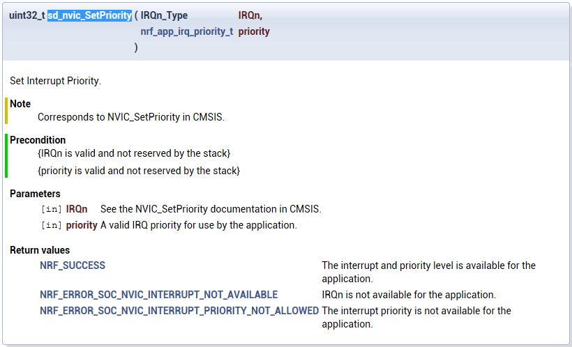
21     err_code = sd_nvic_SetPriority(ADC_IRQn, NRF_APP_PRIORITY_LOW);
22     APP_ERROR_CHECK(err_code);
X设置中断优先级
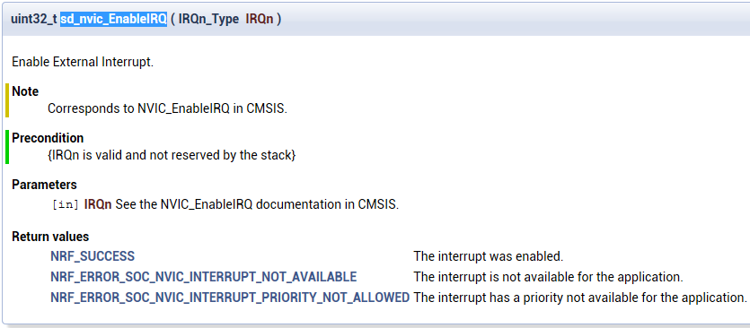
24     err_code = sd_nvic_EnableIRQ(ADC_IRQn);
25     APP_ERROR_CHECK(err_code);
X使能外部中断ADC
那么,综上定时器触发timeout周期性执行battery_start()。在该函数中对AD进行配置然后使能~
接下来深入分析这个AD中断时怎么执行的!
AD中断执行,深入m0内核
顺着ADC_IRQn并不是一个中断回调函数,而是:
 1 typedef enum {
 2 /* -------------------  Cortex-M0 Processor Exceptions Numbers  ------------------- */
 3   Reset_IRQn                    = -15,              /*!<   1  Reset Vector, invoked on Power up and warm reset                 */
 4   NonMaskableInt_IRQn           = -14,              /*!<   2  Non maskable Interrupt, cannot be stopped or preempted           */
 5   HardFault_IRQn                = -13,              /*!<   3  Hard Fault, all classes of Fault                                 */
 6   SVCall_IRQn                   =  -5,              /*!<  11  System Service Call via SVC instruction                          */
 7   DebugMonitor_IRQn             =  -4,              /*!<  12  Debug Monitor                                                    */
 8   PendSV_IRQn                   =  -2,              /*!<  14  Pendable request for system service                              */
 9   SysTick_IRQn                  =  -1,              /*!<  15  System Tick Timer                                                */
10 /* ----------------------  nRF51 Specific Interrupt Numbers  ---------------------- */
11   POWER_CLOCK_IRQn              =   0,              /*!<   0  POWER_CLOCK                                                      */
12   RADIO_IRQn                    =   1,              /*!<   1  RADIO                                                            */
13   UART0_IRQn                    =   2,              /*!<   2  UART0                                                            */
14   SPI0_TWI0_IRQn                =   3,              /*!<   3  SPI0_TWI0                                                        */
15   SPI1_TWI1_IRQn                =   4,              /*!<   4  SPI1_TWI1                                                        */
16   GPIOTE_IRQn                   =   6,              /*!<   6  GPIOTE                                                           */
17   ADC_IRQn                      =   7,              /*!<   7  ADC                                                              */
18   TIMER0_IRQn                   =   8,              /*!<   8  TIMER0                                                           */
19   TIMER1_IRQn                   =   9,              /*!<   9  TIMER1                                                           */
20   TIMER2_IRQn                   =  10,              /*!<  10  TIMER2                                                           */
21   RTC0_IRQn                     =  11,              /*!<  11  RTC0                                                             */
22   TEMP_IRQn                     =  12,              /*!<  12  TEMP                                                             */
23   RNG_IRQn                      =  13,              /*!<  13  RNG                                                              */
24   ECB_IRQn                      =  14,              /*!<  14  ECB                                                              */
25   CCM_AAR_IRQn                  =  15,              /*!<  15  CCM_AAR                                                          */
26   WDT_IRQn                      =  16,              /*!<  16  WDT                                                              */
27   RTC1_IRQn                     =  17,              /*!<  17  RTC1                                                             */
28   QDEC_IRQn                     =  18,              /*!<  18  QDEC                                                             */
29   LPCOMP_COMP_IRQn              =  19,              /*!<  19  LPCOMP_COMP                                                      */
30   SWI0_IRQn                     =  20,              /*!<  20  SWI0                                                             */
31   SWI1_IRQn                     =  21,              /*!<  21  SWI1                                                             */
32   SWI2_IRQn                     =  22,              /*!<  22  SWI2                                                             */
33   SWI3_IRQn                     =  23,              /*!<  23  SWI3                                                             */
34   SWI4_IRQn                     =  24,              /*!<  24  SWI4                                                             */
35   SWI5_IRQn                     =  25               /*!<  25  SWI5                                                             */
36 } IRQn_Type;
哪里会用IRQn_Type呢?
是内核的中断向量部分——
  1 /* ##########################   NVIC functions  #################################### */
  2 /** \ingroup  CMSIS_Core_FunctionInterface
  3     \defgroup CMSIS_Core_NVICFunctions NVIC Functions
  4     \brief      Functions that manage interrupts and exceptions via the NVIC.
  5     @{
  6  */
  7
  8 /* Interrupt Priorities are WORD accessible only under ARMv6M                   */
  9 /* The following MACROS handle generation of the register offset and byte masks */
 10 #define _BIT_SHIFT(IRQn)         (  (((uint32_t)(IRQn)       )    &  0x03) * 8 )
 11 #define _SHP_IDX(IRQn)           ( ((((uint32_t)(IRQn) & 0x0F)-8) >>    2)     )
 12 #define _IP_IDX(IRQn)            (   ((uint32_t)(IRQn)            >>    2)     )
 13
 14
 15 /** \brief  Enable External Interrupt
 16
 17     The function enables a device-specific特殊 interrupt in the NVIC interrupt controller中断向量控制器.
 18
 19     \param [in]      IRQn  External interrupt number. Value cannot be negative.
 20  */
 21 __STATIC_INLINE void NVIC_EnableIRQ(IRQn_Type IRQn)//被动函数
 22 {
 23   NVIC->ISER[0] = (1 << ((uint32_t)(IRQn) & 0x1F));
 24 }
 25
 26
 27 /** \brief  Disable External Interrupt
 28
 29     The function disables a device-specific interrupt in the NVIC interrupt controller.
 30
 31     \param [in]      IRQn  External interrupt number. Value cannot be negative.
 32  */
 33 __STATIC_INLINE void NVIC_DisableIRQ(IRQn_Type IRQn)//被动函数
 34 {
 35   NVIC->ICER[0] = (1 << ((uint32_t)(IRQn) & 0x1F));
 36 }
 37
 38
 39 /** \brief  Get Pending Interrupt
 40
 41     The function reads the pending register in the NVIC and returns the pending bit
 42     for the specified interrupt.
 43
 44     \param [in]      IRQn  Interrupt number.
 45
 46     \return             0  Interrupt status is not pending.
 47     \return             1  Interrupt status is pending.
 48  */
 49 __STATIC_INLINE uint32_t NVIC_GetPendingIRQ(IRQn_Type IRQn)//判断中断是否正在进行
 50 {
 51   return((uint32_t) ((NVIC->ISPR[0] & (1 << ((uint32_t)(IRQn) & 0x1F)))?1:0));
 52 }
 53
 54
 55 /** \brief  Set Pending Interrupt
 56
 57     The function sets the pending bit of an external interrupt.
 58
 59     \param [in]      IRQn  Interrupt number. Value cannot be negative.
 60  */
 61 __STATIC_INLINE void NVIC_SetPendingIRQ(IRQn_Type IRQn)//设置正在进行中断为IRQn
 62 {
 63   NVIC->ISPR[0] = (1 << ((uint32_t)(IRQn) & 0x1F));
 64 }
 65
 66
 67 /** \brief  Clear Pending Interrupt
 68
 69     The function clears the pending bit of an external interrupt.
 70
 71     \param [in]      IRQn  External interrupt number. Value cannot be negative.
 72  */
 73 __STATIC_INLINE void NVIC_ClearPendingIRQ(IRQn_Type IRQn)//清除正在进行中断
 74 {
 75   NVIC->ICPR[0] = (1 << ((uint32_t)(IRQn) & 0x1F)); /* Clear pending interrupt */
 76 }
 77
 78
 79 /** \brief  Set Interrupt Priority
 80
 81     The function sets the priority of an interrupt.
 82
 83     \note The priority cannot be set for every core interrupt.
 84
 85     \param [in]      IRQn  Interrupt number.
 86     \param [in]  priority  Priority to set.
 87  */
 88 __STATIC_INLINE void NVIC_SetPriority(IRQn_Type IRQn, uint32_t priority)//设置中断优先级
 89 {
 90   if(IRQn < 0) {
 91     SCB->SHP[_SHP_IDX(IRQn)] = (SCB->SHP[_SHP_IDX(IRQn)] & ~(0xFF << _BIT_SHIFT(IRQn))) |
 92         (((priority << (8 - __NVIC_PRIO_BITS)) & 0xFF) << _BIT_SHIFT(IRQn)); }
 93   else {
 94     NVIC->IP[_IP_IDX(IRQn)] = (NVIC->IP[_IP_IDX(IRQn)] & ~(0xFF << _BIT_SHIFT(IRQn))) |
 95         (((priority << (8 - __NVIC_PRIO_BITS)) & 0xFF) << _BIT_SHIFT(IRQn)); }
 96 }
 97
 98
 99 /** \brief  Get Interrupt Priority
100
101     The function reads the priority of an interrupt. The interrupt
102     number can be positive to specify an external (device specific)
103     interrupt, or negative to specify an internal (core) interrupt.
104
105
106     \param [in]   IRQn  Interrupt number.
107     \return             Interrupt Priority. Value is aligned automatically to the implemented
108                         priority bits of the microcontroller.
109  */
110 __STATIC_INLINE uint32_t NVIC_GetPriority(IRQn_Type IRQn)//读取一个中断的优先级,如果为正表示是外部中断,为负表示为内部中断
111 {
112
113   if(IRQn < 0) {
114     return((uint32_t)(((SCB->SHP[_SHP_IDX(IRQn)] >> _BIT_SHIFT(IRQn) ) & 0xFF) >> (8 - __NVIC_PRIO_BITS)));  } /* get priority for Cortex-M0 system interrupts */
115   else {
116     return((uint32_t)(((NVIC->IP[ _IP_IDX(IRQn)] >> _BIT_SHIFT(IRQn) ) & 0xFF) >> (8 - __NVIC_PRIO_BITS)));  } /* get priority for device specific interrupts  */
117 }
118
119
120 /** \brief  System Reset
121
122     The function initiates发起 a system reset request to reset the MCU.
123  */
124 __STATIC_INLINE void NVIC_SystemReset(void)
125 {
126   __DSB();                                                     /* Ensure all outstanding memory accesses included
127                                                                   buffered write are completed before reset */
128   SCB->AIRCR  = ((0x5FA << SCB_AIRCR_VECTKEY_Pos)      |
129                  SCB_AIRCR_SYSRESETREQ_Msk);
130   __DSB();                                                     /* Ensure completion of memory access */
131   while(1);                                                    /* wait until reset */
132 }
133
134 /*@} end of CMSIS_Core_NVICFunctions */
绕了一圈最后反推找到ADC中断回调函数在start上面!(瞎了~)
 1 /**@brief Function for handling the ADC interrupt.
 2  * @details  This function will fetch the conversion result from the ADC, convert the value into
 3  *           percentage and send it to peer.
 4  */
 5 void ADC_IRQHandler(void)
 6 {
 7     if (NRF_ADC->EVENTS_END != 0)
 8     {
 9         uint8_t     adc_result;
10         uint16_t    batt_lvl_in_milli_volts;
11         uint8_t     percentage_batt_lvl;
12         uint32_t    err_code;
13
14         NRF_ADC->EVENTS_END     = 0;
15         adc_result              = NRF_ADC->RESULT;
16         NRF_ADC->TASKS_STOP     = 1;
17
18         batt_lvl_in_milli_volts = ADC_RESULT_IN_MILLI_VOLTS(adc_result) +
19                                   DIODE_FWD_VOLT_DROP_MILLIVOLTS;
20         percentage_batt_lvl     = battery_level_in_percent(batt_lvl_in_milli_volts);
21
22         err_code = ble_bas_battery_level_update(&bas, percentage_batt_lvl);
23         if (
24             (err_code != NRF_SUCCESS)
25             &&
26             (err_code != NRF_ERROR_INVALID_STATE)
27             &&
28             (err_code != BLE_ERROR_NO_TX_BUFFERS)
29             &&
30             (err_code != BLE_ERROR_GATTS_SYS_ATTR_MISSING)
31         )
32         {
33             APP_ERROR_HANDLER(err_code);
34         }
35     }
36 }
上面函数先从AD中获得读取值,然后调用updata函数。
其中重点也就是这个ble_bas_battery_level_update函数~
该函数是最上面简介中谈到的一个——
If specified, the module will support notification of the Battery Level characteristic through the ble_bas_battery_level_update() function. If an event handler is supplied by the application, the Battery Service will generate Battery Service events to the application.
该函数首先判断老的电量值和新的是否一样,不一样则更新老的
 1 uint32_t ble_bas_battery_level_update(ble_bas_t * p_bas, uint8_t battery_level)
 2 {
 3     uint32_t err_code = NRF_SUCCESS;
 4
 5     if (battery_level != p_bas->battery_level_last)
 6     {
 7         uint16_t len = sizeof(uint8_t);
 8
 9         // Save new battery value
10         p_bas->battery_level_last = battery_level;
11
12         // Update database
13         err_code = sd_ble_gatts_value_set(p_bas->battery_level_handles.value_handle,
14                                           0,
15                                           &len,
16                                           &battery_level);
17         if (err_code != NRF_SUCCESS)
18         {
19             return err_code;
20         }
21
22         // Send value if connected and notifying
23         if ((p_bas->conn_handle != BLE_CONN_HANDLE_INVALID) && p_bas->is_notification_supported)
24         {
25             ble_gatts_hvx_params_t hvx_params;
26
27             memset(&hvx_params, 0, sizeof(hvx_params));
28             len = sizeof(uint8_t);
29
30             hvx_params.handle   = p_bas->battery_level_handles.value_handle;
31             hvx_params.type     = BLE_GATT_HVX_NOTIFICATION;
32             hvx_params.offset   = 0;
33             hvx_params.p_len    = &len;
34             hvx_params.p_data   = &battery_level;
35
36             err_code = sd_ble_gatts_hvx(p_bas->conn_handle, &hvx_params);
37         }
38         else
39         {
40             err_code = NRF_ERROR_INVALID_STATE;
41         }
42     }
43
44     return err_code;
45 }
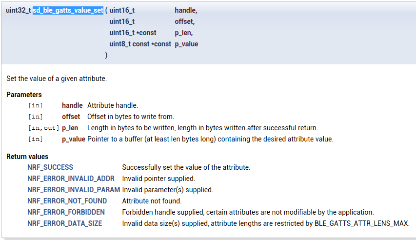
然后调用gatts_value_set更新database
其中——
12         // Update database
13         err_code = sd_ble_gatts_value_set(p_bas->battery_level_handles.value_handle,
14                                           0,
15                                           &len,
16                                           &battery_level);
36 err_code = sd_ble_gatts_hvx(p_bas->conn_handle, &hvx_params);
该函数在上一篇中的timer部分的最后已经详细讲过——
This function checks for the relevant相关的 Client Characteristic Configuration descriptor描述符 value to verify判定 that the relevant operation (notification or indication) has been enabled by the client.
It is also able to update the attribute 属性 value before issuing发出 the PDU(protocol data unit:https://en.wikipedia.org/wiki/Protocol_data_unit && BLE 包结构及传输速率), so that the application can atomically原子级地 perform a value update and a server initiated开始 transaction事务 with a single API call. (仅仅调用一个API就能够将attribute的value有效地发出)If the application chooses to indicate an attribute value, a BLE_GATTS_EVT_HVC will be sent up as soon as the confirmation arrives from the peer.

这样,终于搞通了AD的测量电量和利用BLE发送的全过程!
具体为——
1、首先在timer初始化中产生一个电量测量timer,
2、在timeout的回调函数battery_level_meas_timeout_handler中对AD进行配置并启动AD转换中断
3、在AD中断回调函数ADC_IRQHandler中获取转换的AD值,
4、并调用ble_bas_battery_level_update与老的电量值对比更新database,
5、最后调用sd_ble_gatts_hvx系统API在原子级操作将attribute的value有效地发出。
此外~再来补一下少说的services_init部分
services_init
 1     // Initialize Battery Service
 2     memset(&bas_init, 0, sizeof(bas_init));
 3
 4     // Here the sec level for the Battery Service can be changed/increased.
 5     BLE_GAP_CONN_SEC_MODE_SET_OPEN(&bas_init.battery_level_char_attr_md.cccd_write_perm);
 6     BLE_GAP_CONN_SEC_MODE_SET_OPEN(&bas_init.battery_level_char_attr_md.read_perm);
 7     BLE_GAP_CONN_SEC_MODE_SET_NO_ACCESS(&bas_init.battery_level_char_attr_md.write_perm);
 8
 9     BLE_GAP_CONN_SEC_MODE_SET_OPEN(&bas_init.battery_level_report_read_perm);
10
11     bas_init.evt_handler          = NULL;
12     bas_init.support_notification = true;
13     bas_init.p_report_ref         = NULL;
14     bas_init.initial_batt_level   = 100;
15
16     err_code = ble_bas_init(&bas, &bas_init);
17     APP_ERROR_CHECK(err_code);
同上一篇一样——
最后一个黄线部分阐明了事件如何关联——
The application must propagate BLE stack events to the Battery Service module by calling ble_bas_on_ble_evt() from the from the ble_stack_handler callback.
应用需要把BLE stack events传送给BAS,黄线部分说可以通过在ble_stack_handler的回调函数中调用ble_bas_on_ble_evt来实现~
下面就是初始化并设置ble_stack_handler的回调函数的:ble_evt_dispatch
 1 /**@brief Function for initializing the BLE stack.
 2  *
 3  * @details Initializes the SoftDevice and the BLE event interrupt.
 4  */
 5 static void ble_stack_init(void)
 6 {
 7     uint32_t err_code;
 8
 9     // Initialize the SoftDevice handler module.
10     SOFTDEVICE_HANDLER_INIT(NRF_CLOCK_LFCLKSRC_XTAL_20_PPM, false);
11
12     // Register with the SoftDevice handler module for BLE events.
13     err_code = softdevice_ble_evt_handler_set(ble_evt_dispatch);
14     APP_ERROR_CHECK(err_code);
15
16     // Register with the SoftDevice handler module for BLE events.
17     err_code = softdevice_sys_evt_handler_set(sys_evt_dispatch);
18     APP_ERROR_CHECK(err_code);
19 }
下面这个函数负责将BLE stack事件分派给所有模块
该函数是由ble_stack_handler的回调函数调用的,发生在:This function is called from the BLE Stack event interrupt handler after a BLE sta
 1 /**@brief Function for dispatching a BLE stack event to all modules with a BLE stack event handler.
 2  *
 3  * @details This function is called from the BLE Stack event interrupt handler after a BLE stack
 4  *          event has been received.
 5  *
 6  * @param[in]   p_ble_evt   Bluetooth stack event.
 7  */
 8 static void ble_evt_dispatch(ble_evt_t * p_ble_evt)
 9 {
10     ble_bondmngr_on_ble_evt(p_ble_evt);
11     ble_hrs_on_ble_evt(&m_hrs, p_ble_evt);
12     ble_bas_on_ble_evt(&bas, p_ble_evt);
13     ble_conn_params_on_ble_evt(p_ble_evt);
14     on_ble_evt(p_ble_evt);
15 }
也就是说当应用初始了ble_stack_init之后,一旦有ble协议栈的事件就会通过ble_evt_dispatch分派给每个模块
对于电量检测的ble_bas_on_ble_evt模块有(其他也类似)——
其中on_write(p_bas, p_ble_evt)是手机等客户端向BAS服务写数据时触发的操作~这里先不讲!
 1 /**@brief Function for handling the Application's BLE Stack events.
 2  *
 3  * @details Handles all events from the BLE stack of interest to the Battery Service.
 4  *
 5  * @note For the requirements in the BAS specification to be fulfilled,
 6  *       ble_bas_battery_level_update() must be called upon reconnection if the
 7  *       battery level has changed while the service has been disconnected from a bonded
 8  *       client.
 9  *
10  * @param[in]   p_bas      Battery Service structure.
11  * @param[in]   p_ble_evt  Event received from the BLE stack.
12  */
13 void ble_bas_on_ble_evt(ble_bas_t * p_bas, ble_evt_t * p_ble_evt)
14 {
15     switch (p_ble_evt->header.evt_id)
16     {
17         case BLE_GAP_EVT_CONNECTED:
18             on_connect(p_bas, p_ble_evt);
19             break;
20
21         case BLE_GAP_EVT_DISCONNECTED:
22             on_disconnect(p_bas, p_ble_evt);
23             break;
24
25         case BLE_GATTS_EVT_WRITE:
26             on_write(p_bas, p_ble_evt);
27             break;
28
29         default:
30             // No implementation needed.
31             break;
32     }
33 }
 1 /**@brief Function for handling the Connect event.
 2  *
 3  * @param[in]   p_bas       Battery Service structure.
 4  * @param[in]   p_ble_evt   Event received from the BLE stack.
 5  */
 6 static void on_connect(ble_bas_t * p_bas, ble_evt_t * p_ble_evt)
 7 {
 8     p_bas->conn_handle = p_ble_evt->evt.gap_evt.conn_handle;
 9 }
10
11
12 /**@brief Function for handling the Disconnect event.
13  *
14  * @param[in]   p_bas       Battery Service structure.
15  * @param[in]   p_ble_evt   Event received from the BLE stack.
16  */
17 static void on_disconnect(ble_bas_t * p_bas, ble_evt_t * p_ble_evt)
18 {
19     UNUSED_PARAMETER(p_ble_evt);
20     p_bas->conn_handle = BLE_CONN_HANDLE_INVALID;
21 }
22
23
24 /**@brief Function for handling the Write event.
25  *
26  * @param[in]   p_bas       Battery Service structure.
27  * @param[in]   p_ble_evt   Event received from the BLE stack.
28  */
29 static void on_write(ble_bas_t * p_bas, ble_evt_t * p_ble_evt)
30 {
31     if (p_bas->is_notification_supported)
32     {
33         ble_gatts_evt_write_t * p_evt_write = &p_ble_evt->evt.gatts_evt.params.write;
34
35         if (
36             (p_evt_write->handle == p_bas->battery_level_handles.cccd_handle)
37             &&
38             (p_evt_write->len == 2)
39         )
40         {
41             // CCCD written, call application event handler
42             if (p_bas->evt_handler != NULL)
43             {
44                 ble_bas_evt_t evt;
45
46                 if (ble_srv_is_notification_enabled(p_evt_write->data))
47                 {
48                     evt.evt_type = BLE_BAS_EVT_NOTIFICATION_ENABLED;
49                 }
50                 else
51                 {
52                     evt.evt_type = BLE_BAS_EVT_NOTIFICATION_DISABLED;
53                 }
54
55                 p_bas->evt_handler(p_bas, &evt);
56             }
57         }
58     }
59 }
注:
本篇讲了电量检测服务的业务流程More:
[蓝牙] 1、蓝牙核心技术了解(蓝牙协议、架构、硬件和软件笔记)
[蓝牙] 2、蓝牙BLE协议及架构浅析&&基于广播超时待机说广播事件
[蓝牙] 4、Heart Rate Service module
@beautifulzzzz 2015-12-15 continue~

 浙公网安备 33010602011771号