

Altium脚本开发 Y分形天线
用Altium Designer脚本实现Y分形的平面天线
本文介绍了使用Altium Designer脚本程序生成Y型天线的过程,在窗体中线宽、迭代次数、边框长度可以直接设置(可以设置为10mm X 10mm,也可以设置为100mm X 100mm)。
Y分形天线用户界面由一个窗体、1个TImage控件、3个TLable控件、3个TEdit控件、一个TButton控件构成,
窗体步骤如下:
- 新建一个VB Script Form文件,保存脚本文件,将文件命名为Y分形天线设计。
- 将窗体的Caption属性改为“Y分形天线设计”。
- 在窗体中添加1个TImage控件、3个TLable控件、3个TEdit控件、一个TButton控件。
- 在TImage控件中加入图片,将3个TLable控件的Caption分别改为“边长(mm):”、“线宽(mm):”、“迭代次数:”。将3个TEdit控件的Text属性分别改为“100”、“2”、“4”,将TButton控件的Caption属性改为“生成”。
窗体如下图所示

图元分析:
Y分形天线的基本结构如下所示。基本的图元由主干M、左分支L、右分支R构成,再一次迭代以左分支的终点和右分支的终点上增加一个基本Y型图元。
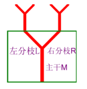
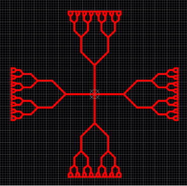
Y分形天线的基本图元为Y型,上下左右四个方向都向前生长Y型的分支,向上Y型每次迭代主干M都是垂直向上,左、下、右Y型分支和上Y型分支相同,可由上Y型生成之后将坐标依次变换一下,得到左、下、右Y型分支,生成的图像如下图所示,源码附后。
源程序:
PI = 3.1415926


'启动PCB服务器
Sub Start_PCBServer()
  Call Client.StartServer("PCB")
  PcbFileName = "PCB1.PcbDoc"
  Set Document = Client.OpenDocument("PCB", PcbFileName)

  If Not (Document Is Nothing) Then
    'Add this schematic sheet in the newly created PCB project in DXP.
    Set Workspace = GetWorkspace

    If Not (Workspace Is Nothing) Then
      Workspace.DM_FocusedProject.DM_AddSourceDocument(Document.FileName)
    End If
    Client.ShowDocument(Document)
  End If
End Sub

'在PCB的顶层画直线函数
'Draw Line Function
Sub Paint_Line(x1,y1,x2,y2)
  Dim Board
  Dim Track
  Set Board = PCBServer.GetCurrentPCBBoard
  Track = PCBServer.PCBObjectFactory(eTrackObject,eNoDimension,eCreate_Default)
  Track.X1 = MMsToCoord(CLng(x1)+Board.GetState_XOrigin/10000*0.0254)
  Track.Y1 = MMsToCoord(CLng(y1)+Board.GetState_XOrigin/10000*0.0254)
  Track.X2 = MMsToCoord(CLng(x2)+Board.GetState_XOrigin/10000*0.0254)
  Track.Y2 = MMsToCoord(CLng(y2)+Board.GetState_XOrigin/10000*0.0254)
  Track.Layer = eTopLayer
  Track.Width = MMsToCoord(Round(Edit2.Text))
  Board.AddPCBObject(Track)
  Board.LayerIsDisplayed(ALayer) = True
End Sub


'画矩形框函数,这里是画PCB的外框
'Draw rectangle Function
Sub Paint_Rectangle(x1,y1,x2,y2)
  call Paint_Line(x1,y1,x2,y1)
  call Paint_Line(x1,y1,x1,y2)
  call Paint_Line(x1,y2,x2,y2)
  call Paint_Line(x2,y1,x2,y2)
End Sub

'刷新视图
Sub Action_Redraw()
  Call Client.SendMessage("PCB:Zoom","Action=Redraw", 255, Client.CurrentView)
  Call Client.SendMessage("PCB:Zoom","Action=All", 255, Client.CurrentView)
End Sub


'设置相对坐标原点函数
'SetState_Origin
Sub Set_Origin()
  Set Board = PCBServer.GetCurrentPCBBoard
  Board.SetState_YOrigin(80000000)
  Board.SetState_XOrigin(80000000)
End Sub


'将矩形框作为PCB的外框
Sub Board_Shape()
  Call AddStringParameter("Scope", "All")
  RunProcess("PCB:Select")

  Call AddStringParameter("Mode", "BOARDOUTLINE_FROM_SEL_PRIMS")
  RunProcess("PCB:PlaceBoardOutline")

  Call AddStringParameter("Size", "2.500MM")
  RunProcess("PCB:SnapGrid")

  Call AddStringParameter("MeasurementUnit", "Toggle")
  RunProcess("PCB:DocumentPreferences")
End Sub


'控件响应函数
Sub Button1Click(Sender)
  call Start_PCBServer() 'Start PCBServer
  Board_chang = Round(Edit1.Text)
  Iter_Num = Round(Edit3.Text) 'Get Iteration Number

  call Set_Origin() 'Set Shape Relative to the origin
  call Paint_Rectangle(-Board_chang/2,-Board_chang/2,Board_chang/2,Board_chang/2)
  Call Board_Shape()
  Call Y_Shape(0,0,30,4)
  Action_Redraw()
  Close
End Sub


'关键画基本图元的函数
Sub Y_Shape(x,y,L,Iter_Num)
  a = PI/4
  L1=L*2/3
  If Iter_Num=0 Then 'If Iter_Num = 0
    Call Y_Xing(x,y,L,L1,a) 'Draw Y
  Else
    Call Y_Xing(x,y,L,L1,a) 'Draw Y

    Call Y_Shape(x-L1*sin(a),y+L+L1*cos(a),L/2,Iter_Num-1)
    Call Y_Shape(x+L1*sin(a),y+L+L1*cos(a),L/2,Iter_Num-1)
  End If
End Sub

Sub Y_Xing(x,y,L,L1,a)
  Call Paint_Line(x,y,x,y+L) 'Draw Vertical Line
  Call Paint_Line(x,y+L,x-L1*sin(a),y+L+L1*cos(a))	       'Draw Left Diagonal Line
  Call Paint_Line(x,y+L,x+L1*sin(a),y+L+L1*cos(a))	       'Draw Right Diagonal Line

  'Draw Left Y
  Call Paint_Line(-y,x,-(y+L),x) 'Draw Vertical Line
  Call Paint_Line(-(y+L),x,-(y+L+L1*cos(a)),x-L1*sin(a))	   'Draw Left Diagonal Line
  Call Paint_Line(-(y+L),x,-(y+L+L1*cos(a)),x+L1*sin(a))	   'Draw Right Diagonal Line

  'DraW Down Y
  Call Paint_Line(x,-y,x,-(y+L)) 'Draw Vertical Line
  Call Paint_Line(x,-(y+L),x-L1*sin(a),-(y+L+L1*cos(a)))	   'Draw Left Diagonal Line
  Call Paint_Line(x,-(y+L),x+L1*sin(a),-(y+L+L1*cos(a)))	   'Draw Right Diagonal Line

  'Draw Right Y
  Call Paint_Line(y,-x,y+L,-x) 'Draw Vertical Line
  Call Paint_Line(y+L,-x,y+L+L1*cos(a),-(x-L1*sin(a)))	       'Draw Left Diagonal Line
  Call Paint_Line(y+L,-x,y+L+L1*cos(a),-(x+L1*sin(a)))       'Draw Right Diagonal Line
End Sub
代码:
https://files.cnblogs.com/files/xiongshuang/Y%E5%88%86%E5%BD%A2%E5%A4%A9%E7%BA%BF%E7%9A%84%E8%AE%BE%E8%AE%A1.zip
参考资料:
[1]付丽华.一种基于Y分形的平面微带天线设计与优化[EB/OL].http://www.elecfans.com/soft/69/2019/20190412905256.html,2019.
[2] Altium Limited.PCB API Design Objects Interfaces[EB/OL].https://techdocs.altium.com/display/SCRT/PCB+API+Design+Objects+Interfaces,2017-9-13.

