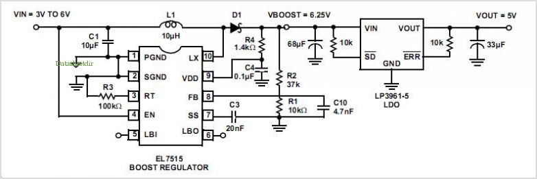
Tracking Boost Regulator TYPICAL 5V REGULATION WITH BOOST CONVERTER AND LDO
Cs5171: Tracking Boost Regulator
Adding a current mirror circuit to a typical boost circuit allows the user to select the amount of boost voltage
and ensure a constant difference between input and output voltage.
This is useful for high side drive applications where a simple voltage doubling circuit is not practical,
either because of the voltage range of the components involved or where the input voltage CAN vary widely.
This circuit CAN also be used at the front end of a power supply
to ensure that the PWM Controller has enough voltage to start correctly in low input voltage conditions.
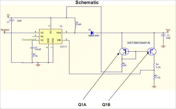
The schematic shown will maintain a 10V difference between Vin and Vout and is easily changed to provide other voltages.
The PWM in the design example is the CS5171.
However, this circuit CAN be used with any boost controller or Regulator The current mirror circuit,
comprising the dual PNP Transistor Q1 and the associated resistors,
establishes a current that depends on the voltage difference between Vin and Vout.
The dual PNP Transistor NST30010MXV6 has a Vceo of 30 V so it is used in this example.
If higher output voltages are required a device such as the BC856BDW1T1G has a Vceo of 65 V.