
PID控制器(比例-积分-微分控制器)- I
形象解释PID算法
小明接到这样一个任务:
有一个水缸点漏水(而且漏水的速度还不一定固定不变),要求水面高度维持在某个位置,一旦发现水面高度低于要求位置,就要往水缸里加水。
小明接到任务后就一直守在水缸旁边,时间长就觉得无聊,就跑到房里看小说了,每30分钟来检查一次水面高度。水漏得太快,
每次小明来检查时,水都快漏完了,离要求的高度相差很远,小明改为每3分钟来检查一次,结果每次来水都没怎么漏,不需要加水,来得太频繁做的是无用功。
几次试验后,确定每10分钟来检查一次。这个检查时间就称为采样周期。
开始小明用瓢加水,水龙头离水缸有十几米的距离,经常要跑好几趟才加够水,于是小明又改为用桶加,一加就是一桶,跑的次数少了,加水的速度也快了,
但好几次将缸给加溢出了,不小心弄湿了几次鞋,小明又动脑筋,我不用瓢也不用桶,老子用盆,几次下来,
发现刚刚好,不用跑太多次,也不会让水溢出。这个加水工具的大小就称为比例系数。
小明又发现水虽然不会加过量溢出了,有时会高过要求位置比较多,还是有打湿鞋的危险。他又想了个办法,在水缸上装一个漏斗,
每次加水不直接倒进水缸,而是倒进漏斗让它慢慢加。这样溢出的问题解决了,但加水的速度又慢了,有时还赶不上漏水的速度。
于是他试着变换不同大小口径的漏斗来控制加水的速度,最后终于找到了满意的漏斗。漏斗的时间就称为积分时间 。
小明终于喘了一口,但任务的要求突然严了,水位控制的及时性要求大大提高,一旦水位过低,必须立即将水加到要求位置,而且不能高出太多,否则不给工钱。
小明又为难了!于是他又开努脑筋,终于让它想到一个办法,常放一盆备用水在旁边,一发现水位低了,不经过漏斗就是一盆水下去,这样及时性是保证了,但水位有时会高多了。
他又在要求水面位置上面一点将水凿一孔,再接一根管子到下面的备用桶里这样多出的水会从上面的孔里漏出来。这个水漏出的快慢就称为微分时间。
拿一个水池水位来说,我们 可以制定一个规则,
把水位分为超高、高、较高、中、较低、低、超低几个区段;
再把水位波动的趋势分为甚快、快、较快、慢、停几个区段,并区分趋势的正负;
把输出分为超大幅 度、大幅度、较大幅度、微小几个区段。
当水位处于中值、趋势处于停顿的时候,不调节;
当水位处于中值、趋势缓慢变化的时候,也可以暂不调节;
当水位处于较高、趋势缓慢变化 的时候,输出一个微小调节两就够了;
当水位处于中值、趋势较快变化的时候,输出进行叫 大幅度调节……。
如上所述,我们需要制定一个控制规则表,然后制定参数判断水位区段的界值、波动趋 势的界值、输出幅度的界值。
根据设备有所不同,比例带一般为2~10%(温度控制)。
但是,仅仅是P控制的话,会产生下面将提到的offset (稳态误差),所以一般加上积分控制(I),以消除稳态误差。
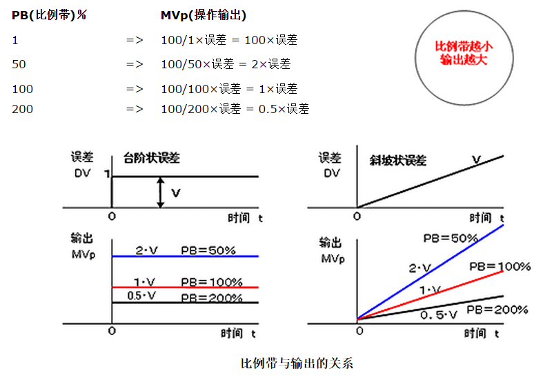
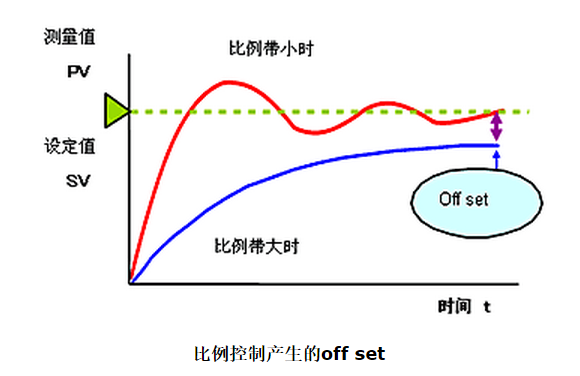
比例控制中,经过一定时间后误差稳定在一定值时,此时的误差叫做稳态误差(off set)。
仅用比例控制的时候,根据负载的变动及设备的固有特性不同,会出现不同的稳态误差。
负载特性与控制特性曲线的交点和设定值不一致是产生稳态误差的原因。
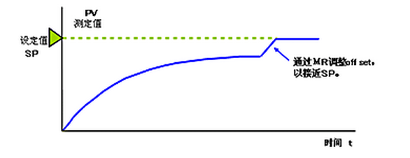
比例带小时不会产生。为消除稳态误差,我们设定手动复位值--manual reset值(MR),以消除控制误差。
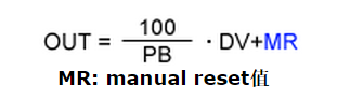
为此,将MR(manual reset值)设为可变,则可自由整定(即调整)调节器的输出。
只要手动操作输出相当于offset的量,就能与目标值一致。
这就叫做手动复位(manual reset),通常比例调节器上配有此功能。
在实际的自动控制中,每次发生off set时以手动进行reset的话,这样并不实用。
在后面将叙述的积分控制功能,能自动消除稳态误差。
所谓积分控制(I),就是在出现稳态误差时自动的改变输出量,使其与手动复位动作的输出量相同,达到消除稳态误差的目的。
当系统存在误差时,进行积分控制,根据积分时间的大小调节器的输出会以一定的速度变化,只要误差还存在,就会不断的进行输出。
积分时间的定义:
当积分项和比例项对于控制器的输出的贡献相同,即积分作用重复了一次比例作用时所花费的时间,就是积分时间。

微分控制(D)的功能是通过误差的变化率预报误差信号的未来变化趋势。
通过提供超前控制作用,微分控制能使被控过程趋于稳定。
因此,它经常用来抵消积分控制产生的不稳定趋势。

微分时间的定义:
当输入量持续的以一定速率变化时,微分项和比例项对于控制器的输出的贡献相同,
即微分作用重复了一次比例作用时所花费的时间,就是微分时间。
PID Control
PID stands for Proportional, Integral, Derivative.
PID control provides a continuous variation of output within a control loop feedback mechanism
to accurately control the process, removing oscillation and increasing efficiency.
How Do PID Controllers Work?
Where proportional control is used to minimize the oscillation characteristic of on/off control,
PID control goes that bit further to reduce errors and provide accuracy and stability in a process.
It does this by using the integral action and derivative actions to eliminate control deviation errors
and to manage rapid process movements.
All three PID terms need to tuned appropriately for the application requirements to achieve the best control.

For a high level of control, digital PID controllers are often used.
These typically come in the form of PID Temperature Controllers or
PID Process Controllers and can be single, dual or multi-loop instruments.
PID control is used for a variety of process variables such as; Temperature, Flow and Pressure.
Typically, challenging applications such as industrial heat treatment processes,
ovens and furnaces use PID controllers as well as in the scientific and
lab sector where precision and reliability is essential to the quality of a control application.
For a detailed insight into how PID Controllers work please refer to the PID Controller Wiki page.
To achieve the best levels of control it is necessary to tune PID controllers, this can be done in a number of ways.
Manual PID Tuning
Controllers will enable manual PID tuning meaning the P, I and D variables must
be manually calculated and set using the controller menu.
This requires a reasonable level of knowledge and understanding from the user to be able to carry out the calculation.
Often this may still require some trial and error testing.
Manual tuning can be extremely time consuming compared to the alternatives.
PID Auto-Tuning
These days, most products will support auto-tuning (also known as self-tuning) of PID settings.
Typically the way this works will depend on which manufacturer’s product you are using,
but commonly they use a rule based calculation in the same way that an experienced engineer would.
Auto-tuning can either take place at the set-point or with some controllers it occurs as the load is being heated up from the ambient temperature.
More recently, controllers have introduced a number of options for auto-tuning PID settings.
These allow the settings to be more closely aligned to a specific application’s requirements
for example prioritising the minimisation of overshoot over the time it takes to reach the set-point.
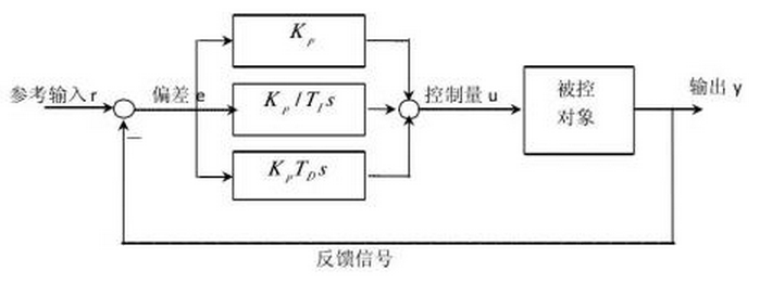
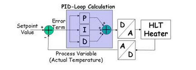
PID控制系统
连续一时间PID控制系统如图所示。
D(s)为控制器。在PID控制系统中,D(s)完成PID控制规律,称为PID控制器。
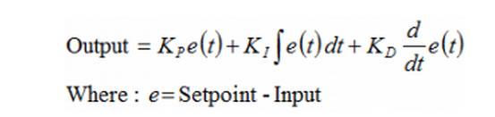
PID控制器是一种线性控制器,用输出量y(t)和给定量r(t)之间的误差的时间函数e(t)=r(t)-y(t)。
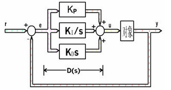
图中的比例,积分,微分的线性组合,构成控制量u(t)称为
比例(Proportional),积分(Integrating),微分(Differentiation)控制,简称PID控制。
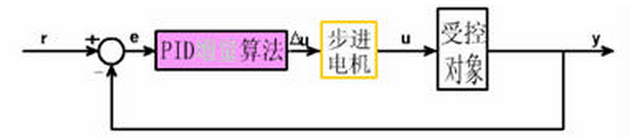
增量算法
当执行机构需要的不是控制量的绝对值,而是控制量的增量(例如去驱动步进电动机)时,需要用PID的“增量算法”。
比例,积分,微分
我们先来了解下正式的定义,P,I,D分别代表控制算法中的三个组成部分:比例,积分,微分。
比例
阀门驱动的准则之一是比例偏差,指的是系统读数与设定值间的差异,该偏差乘以P值后的数值被赋予求和地址位。
由此可见,如果实际读数与设定值之间的差异很大,控制器就会快速驱动阀门工作以试图到达设定值,可以把它看作踩油门。
积分
由微积分曲线图可知,积分是某两点区间内曲线下方包围的面积,通常即起始时间点与结束时间点。
说得更实际点,就是从零点开始的读数总和或误差总和。
调节P值和D值仅着力于当下或前一刻的测量状态,I值则利用更多较早的数据将当前系统读数修正至设定值。
艾里卡特大多数将质量流量控制器、压力控制器的I值设为零,P值与D值被计入以每秒1000次的速度更新的求和地址位,
免除用户输入I值的必要。求和地址位的数值即用来按比例地控制阀门开度。
微分
根据微积分函数表达式y=T(dx/dt),微分是变量(x)对时间(t)的求导。
就质量流量控制器而言,流量值就是这个变量(x)。
PID控制算法会将求和地址位数值,减去dx/dt乘以D值后的值,作为阻尼项,因而可以将D值理解为刹车。
PID控制器是一种线性调节器,这种调节器是将系统的给定r与实际输出值y构成的控制偏差
e =y- r的比例、积分、微分,通过线性组合构成控制量输入给控制对象。
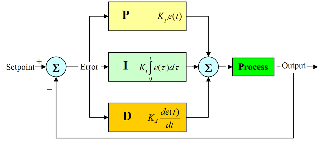
PID控制器各校正环节的作用
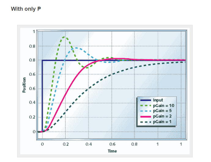
比例环节:快速减小偏差,加快响应速度,但是过大会使系统超调量增大,影响系统稳定性。
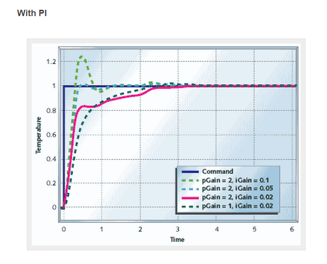
积分环节:主要用于减小稳态误差,但会使系统响应速度减慢。
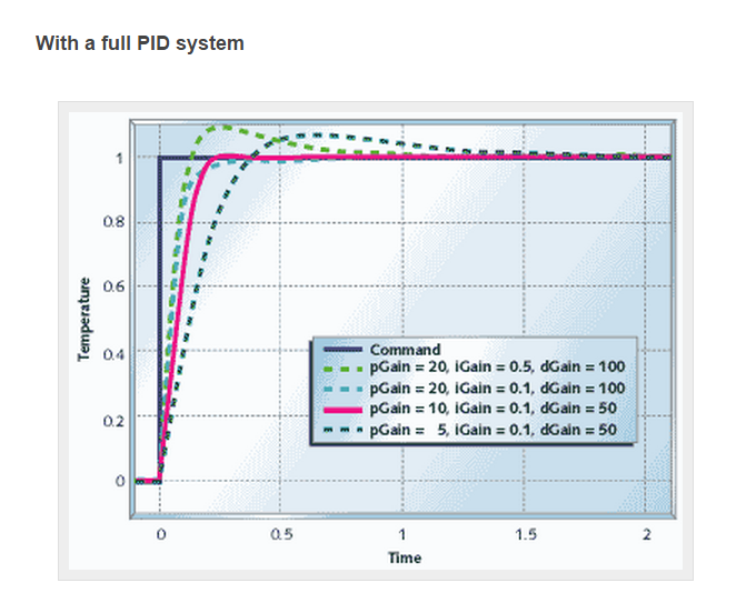
微分环节:在系统中偏差信号变得太大之前引入一个修正信号,从而加快系统的动作速度,减小了调节时间,减少了系统的超调量。
PID控制器
PID Theory
PID控制器(比例-积分-微分控制器),由比例单元P、积分单元I和微分单元D组成。
通过Kp,Ki和Kd三个参数的设定。PID控制器主要适用于基本上线性,且动态特性不随时间变化的系统。
PID控制器是一个在工业控制应用中常见的反馈回路部件。
这个控制器把收集到的数据和一个参考值进行比较,然后把这个差别用于计算新的输入值,
这个新的输入值的目的是可以让系统的数据达到或者保持在参考值。
PID控制器可以根据历史数据和差别的出现率来调整输入值,使系统更加准确而稳定。
PID控制器的比例单元P、积分单元I和微分单元D分别对应目前误差、过去累计误差及未来误差。
若是不知道受控系统的特性,一般认为PID控制器是最适用的控制器。
借由调整PID控制器的三个参数,可以调整控制系统,设法满足设计需求。
控制器的响应可以用控制器对误差的反应快慢、控制器过冲的程度及系统震荡的程度来表示。
不过使用PID控制器不一定保证可达到系统的最佳控制,也不保证系统稳定性。
有些应用只需要PID控制器的部分单元,可以将不需要单元的参数设为零即可。
因此PID控制器可以变成PI控制器、PD控制器、P控制器或I控制器。
其中又以PI控制器比较常用,因为D控制器对回授噪声十分敏感,
而若没有I控制器的话,系统不会回到参考值,会存在一个误差量。
PID是以它的三种纠正算法而命名。
受控变数是三种算法(比例、积分、微分)相加后的结果,即为其输出,
其输入为误差值(设定值减去测量值后的结果)或是由误差值衍生的信号。
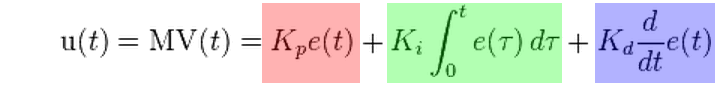
若定义 u(t) 为控制输出,PID算法可以用下式表示:
比例控件
比例控制考虑当前误差,误差值和一个正值的常数Kp(表示比例)相乘。
Kp只是在控制器的输出和系统的误差成比例的时候成立。
比如说,一个电热器的控制器的比例尺范围是10°C,它的预定值是20°C。
那么它在10°C的时候会输出100%,在15°C的时候会输出50%,在19°C的时候输出10%,
注意在误差是0的时候,控制器的输出也是0。
比例控制的输出如下:
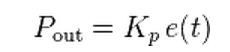
若比例增益大,在相同误差量下,会有较大的输出,
但若比例增益太大,会使系统不稳定。相反的,
若比例增益小,若在相同误差量下,其输出较小,因此控制器会较不敏感的。
若比例增益太小,当有干扰出现时,其控制信号可能不够大,无法修正干扰的影响。
The proportional term changes the output according to the error.
A simple proportional controller has only one control parameter, the Kp.
By changing this parameter, the controller becomes more or less reactive in changes.
The higher the Kp parameter, the faster the system will try to reach the set-point,
but also high proportional gain turns the system unstable
and it oscillates around the set-point.
On the other hand, if the Kp is low, then the the system will stabilize with a constant error bellow (or above) the set-point,
because the output will not provide sufficient power for the system to reach the final position.
Here is a graph to better understand this parameter:

The red line shows the response of the system with a high Kp.
The system will try to reach the set-point faster, but the overshoot is high as well as the error.
This drives the system into an unstable state in which it oscillates around the set-point.
The blue line shows the response with a low Kp.
The system will reach the set-point slower and it will cause a much smaller overshoot.
But after a few oscillations, the controller output does not provide enough power to change the system,
thus it will remain stable a little bellow the set-point.
稳态误差
比例控制在误差为0时,其输出也会为0。
若要让受控输出为非零的数值,就需要有一个稳态误差或偏移量。
稳态误差和比例增益成正比,和受控系统本身的增益成反比。
若加入一偏置,或是加入积分控制,可以消除稳态误差。
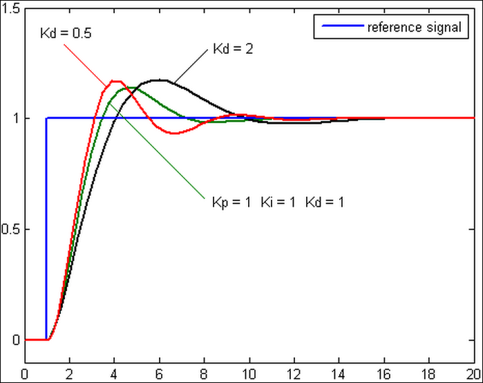
不同比例增益Kp下,受控变数对时间的变化(Ki和Kd维持定值)
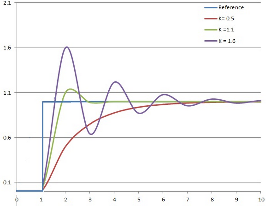
积分控件
积分控制考虑过去误差,将误差值过去一段时间和(误差和)乘以一个正值的常数Ki。
Ki从过去的平均误差值来找到系统的输出结果和预定值的平均误差。
一个简单的比例系统会震荡,会在预定值的附近来回变化,因为系统无法消除多余的纠正。
通过加上负的平均误差值,平均系统误差值就会渐渐减少。
所以,最终这个PID回路系统会在设定值稳定下来。积分控制的输出如下:

积分控制会加速系统趋近设定值的过程,并且消除纯比例控制器会出现的稳态误差。
积分增益越大,趋近设定值的速度越快,不过过因为积分控制会累计过去所有的误差,可能会使回授值出现过冲的情形。
A proportional system is usually not sufficient to eliminate the error.
The system must not only change its output according to the current error,
but it must also be able to watch and change the output according to the past errors.
The integral is the sum of the errors over time.
What this means is that, if the error is big, then the integral builds up as time passes
and the output changes rapidly to eliminate the error.
Now suppose that we have the same example as before, a proportional system that has a low Kp.
First of all, the system will respond much faster at the beginning, because the error will build up a big integral.
Then, when the system is stabilized little bellow the set-point, the integral will take over.
This small error is added over time to increase the integral, and finally it will change the system's output.
Finally, the system will stabilize onto the set-point.
Now, suppose that we have a proportional system with low Kp and an integral term.
Such a system is named PI, and here is how the system reacts as Ki changes:

A high integral gain (Ki) (red line) causes a faster system response, but also causes overshoot.
Unlike the pure proportional system, despite the overshoot, the system is not driven into an unstable state.
After a few oscillations the system will stabilize on the set-point.
As the integral gain gets smaller (blue line), the system responses slower,
but it stabilizes much faster with less oscillations.
The optimal integral gain (purple line) causes the system to respond very slow
but it stabilizes on the set-point with almost no oscillations.
微分控件
微分控制考虑将来误差,计算误差的一阶导,并和一个正值的常数Kd相乘。
这个导数的控制会对系统的改变作出反应。
导数的结果越大,那么控制系统就对输出结果作出更快速的反应。
这个Kd参数也是PID被称为可预测的控制器的原因。
Kd参数对减少控制器短期的改变很有帮助。
一些实际中的速度缓慢的系统可以不需要Kd参数。
微分控制的输出如下:

微分控制可以提升整定时间及系统稳定性。
不过因为纯微分器不是因果系统,因此在PID系统实现时,一般会为微分控制加上一个低通滤波器以限制高频增益及噪声。
实务上较少用到微分控制,估计PID控制器中只有约20%有用到微分控制。
The third and last term is the Derivative.
This term calculates the rate of change of the error and adds to the output accordingly.
If the error changes slow, then the derivative is increased in order to make the PID system respond faster.
On the other hand, if the error is changes rapidly, the derivative is decreased
in order to make the system more stable and avoid oscillations.
Tuning a PID controller
The process of setting the P, I and D parameters to obtain an ideal response of the system is called tuning.
Over the years, several tuning methods have been described,
but we will discuss only the Ziegler-Nichols method and of course the manual tuning.
The tuning time is relative to the system type and speed of change.
If a system has a rapid response, then the tuning time is very short.
On the other hand, a slow response system has a very long tuning time.
A fast-response system is for example a robot positioning system.
An example of a slow response system could be a large water tank heater.
It is obvious that a parameter change in the robot positioning system will have an immediate response at the robot's behavior,
while a parameter change in the water tank heater system may need several minutes for the systems to react.
Manual PID Tuning
If someone wants to tune a PID system with this method, then he first must be sure
that he understands what each parameter does and how each one affects the system,
otherwise this can be a headache. These are the steps for this method:
- The I and D terms are set to zero
- The P term is increased until the system oscillates
- The P term is increased slowly to increase the system response, but it must not become unstable
- When the P term is set to obtain a desired fast response, the I term is increased to stop the oscillations.
This will reduce the steady state error but may increase the overshoot.
Faster system response may require some amount of overshoot. - When I is set to desired amount of overshoot and minimal state error,
the D term is set until the system achieves an acceptable quick loop to its set-point.
Increasing the D term will result in decreasing the overshoot and yields higher gain with stability,
but it may cause the system to be very sensitive to noise.
Tuning a PID system with the Ziegler-Nichols method
The process of setting the optimal gains for P, I and D to get an ideal response from a control system is called tuning.
There are different methods of tuning of which the “guess and check” method and the Ziegler Nichols method will be discussed.
The gains of a PID controller can be obtained by trial and error method.
Once an engineer understands the significance of each gain parameter, this method becomes relatively easy.
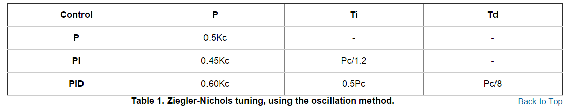
In this method, the I and D terms are set to zero first and the proportional gain is increased until the output of the loop oscillates.
As one increases the proportional gain, the system becomes faster, but care must be taken not make the system unstable.
Once P has been set to obtain a desired fast response, the integral term is increased to stop the oscillations.
The integral term reduces the steady state error, but increases overshoot.
Some amount of overshoot is always necessary for a fast system so that it could respond to changes immediately.
The integral term is tweaked to achieve a minimal steady state error.
Once the P and I have been set to get the desired fast control system with minimal steady state error,
the derivative term is increased until the loop is acceptably quick to its set point.
Increasing derivative term decreases overshoot and yields higher gain with stability
but would cause the system to be highly sensitive to noise.
Often times, engineers need to tradeoff one characteristic of a control system for another to better meet their requirements.
The Ziegler-Nichols method is another popular method of tuning a PID controller.
It is very similar to the trial and error method wherein I and D are set to zero and P is increased until the loop starts to oscillate.
Once oscillation starts, the critical gain Kc and the period of oscillations Pc are noted.
The P, I and D are then adjusted as per the tabular column shown below.
The Ziegler-Nichols method was introduced by John G. Ziegler and Nathaniel B. Nichols in the 1940s.
To tune a system with the Ziegler-Nichols method,
the engineer must first define the critical P gain, which we will name Kc.
This is how its done:
- The I and D terms are set to zero
- The P term is increased until the system oscillates in a stable rate. This will be the Kc
Once the Kc is defined, then the engineer must measure the oscillation period.
It is the same like measuring the period of an AC signal.
This will be the Pc.
Finally, the user can calculate the values for P,I and D parameters using the following table:
If you're wondering what the Ti and Td terms are, these are common parameters in a PID controller.
A typical PID controller has three parameters, K, Ti and Td, but there are many different kinds of PID controllers.
For example, a PID controller with set-point weighting and derivative filter has six parameters K, Ti, Td, Tf , b and c.
Parameters b and c are called set-point weights.
They have no influence on the response to disturbances but they have a significant influence on the response to set-point changes,
so you do not need to worry about them when tuning a PID system.
Example
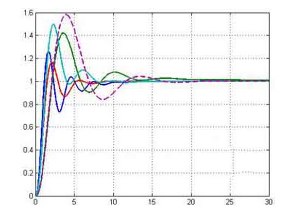
Here is an example of a system that we want to tune with the Ziegler-Nichols method.
First, we need to find the critical P gain.
So, we make the I and D parameters zero and we let the controller operate as a simple proportional controller (only P).
Then, we start to increase the parameter P and write down the system's response.
Here are 4 typical characteristics of a system's response in relation to the P change:
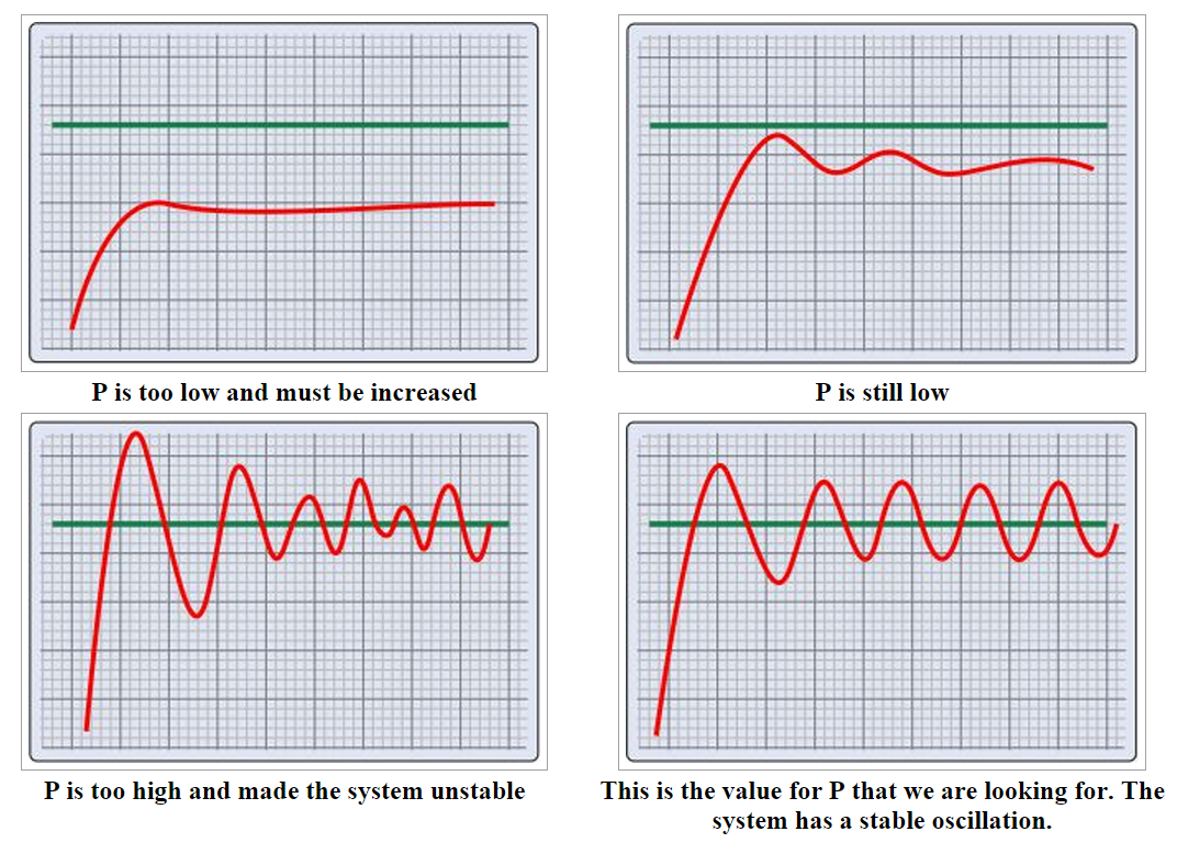
Suppose that the setting for P is 20. So, Kc is 20.
Now we can take a closer look at the last chart:
The horizontal axis shows the time in seconds.
As you can see, the oscillation has a period of about 15 seconds (45 to 60 seconds).
So, the second parameter that we need, the Pc, is 15' seconds.
To get the PID parameters for our controller, we need to use these values with the Ziegler-Nichols table:
P = 0.60 x Kc => P = 0.6 x 20 => P = 12
Ti = 0.5 x Pc => Ti = 0.5 x 15 => Ti = 7.5
Td = Pc / 8 => Td = 15 / 8 => Td = 1.87
After 2 pages of theory and mathematical hocus-pocus,
there will be people that still are not able to write software for a PID controller.
For those people, i have 2 good news:
First is that i found the best documentation for making a PID controller with a PIC microcontroller.
It is the Application Note 937 from Microchip (who else):
Second good news: A PID controller example explained in simple words
I understand that not all people feel comfortable with mathematics,
but many would like to make a PID controller for number of reasons.
The integral term is by far the hardest to decipher.
Instead of just explaining the integral term, i will explain a complete (and simple) PID controller with an example.
I bet that after this, everyone will be able to make one (as long as he know how to program a microcontroller of course).
So, it goes like this: We want to control the temperature of a water heater.
The heater resistor is controlled by a TRIAC, and the microcontroller controls the gate of that TRIAC (it could operate as a dimmer for example).
A temperature sensor is placed in the water and gives feedback to the microcontroller in degrees Celsius (oC).
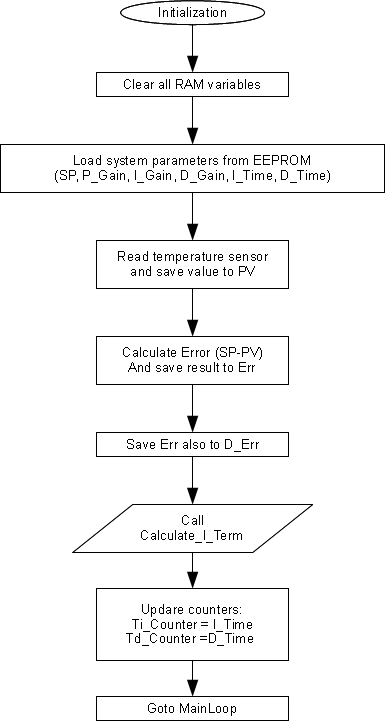
The system has these parameters which you must define as RAM variables,
and also it is good to save them in an EEPROM memory because you do not want to define them every time the system restarts:
- SP - The Set-Point of the system, the temperature that we want to achieve
- P_Gain - The gain for the Proportional term
- I_Gain - The gain for the Integral term
- D_Gain - The gain for the Derivative term
- I_Time - Reset time, this is the Ti parameter that we saw on previous pages
- D_Time - Derivative time, this is the Td parameter that we saw on previous pages
You will also need to define these additional RAM variables:
- P_Term - The Proportional term to be added to the output.
- I_Term - The Integral term to be added to the output.
- D_Term - The Derivative term to be added to the output.
- PV - The Process Variable, this is the temperature that the sensor reads.
- Err - This will hold the current error (SP-PV).
- Acc_Err - This is the accumulated error to help calculate the Integral term
- D_Err - This is the derivative error to help calculate the Derivative term
- Ti_Counter - A countdown counter for the Integral accumulation routine
- Td_Counter - A countdown counter for the Derivative error calculation
- P_Out - The output power calculated by the PID
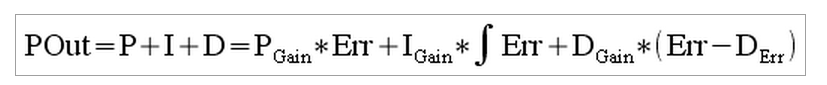
This is the simplest PID controller.
The output of this system is described by this function (do not be scared if you know little about mathematics)
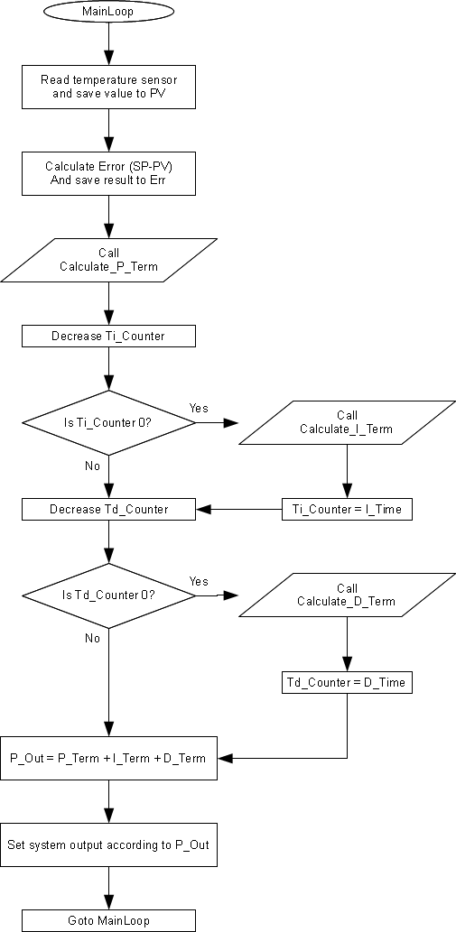
The microcontroller will run an infinite loop, during which it will calculate the PID terms and control the output.
I call this routine "MainLoop". During start-up, the microcontroller will run the "Initialization" routine.
Here are the flow chart of the Initialization and the MainLoop routines:
Initialization
MainLoop
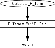
Finally, there are 3 more subroutines,
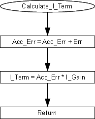
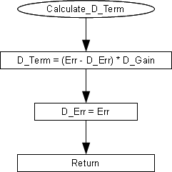
Calculate_P_Term, Calculate_I_Term andCalculate_D_Term.
Here are the flow charts for those:
How it works then?
First of all, i want you to agree that, behind the mask of the hard math,
there is only a simple program with additions and subtractions (ok, and some multiplications and divisions maybe).
I assume that you do know how to read a flowchart and i will not go into details.
Regarding the symbols that i use:
An ellipse indicates the start and the name of the (sub)routine that follows,
a rectangle has the parts of a routine that have to be translated directly into code,
a parallelogram defines a call to another sub-routine and
a diamond defines an IF case, with a YES or NO branch.
Looking into the MainLoop, you can see that the system reads the temperature and calculates the error in every loop.
The error is calculated by subtracting the PV from the SP (Err=SP-PV).
If for example we want the water to have 80oC temperature (SP) and the current temperature is 25oC (PV), the error (Err) is 80-25=55oC.
Using this error, the program calculates the P_Term (Calculate_P_Term subroutine),
simply by multiplying the error by the P_Gain (P_Term=Err*P_Gain).
Until now, this is the typical operation of a simple P-controller.
Now to add the I term.
Looking again into the MainLoop, we see that the Calculate_I_Term subroutine is NOT called in every loop.
Instead, a counter is used (Ti_Counter). The initial value of this counter is taken from the I_Time system parameter (Ti).
The counter is decreased on every loop.
When the counter becomes zero, the Calculate_I_Term subroutine is called.
So, this is where the Ti parameter is used.
Unlike the P_Term, the I_Term is calculated only once every Ti loop cycles.
To calculate the I_Term the system adds the current error (Err) to a variable named Acc_Err.
This variable accumulates all past errors and therefore is called Accumulated Error.
The I_Term is then calculated by multiplying this variable by the I_Gain (I_Term=Acc_Err*I_Gain).
Now you understand the purpose of the Ti parameter.
If the system did not have this parameter, it would accumulate the current errors constantly,
and therefore the I_Term would become huge and it would overshadow the P_Term and D_Term.
Finally, the D_Term.
Similar to the I_Term, the D_Term has a different countdown timer (Td_Counter),
so the Calculate_D_Term subroutine is called once every D_Time (Td) cycles.
To calculate the D_Term, the system must know the previous error.
The previous error is saved in the D_Err variable.
So, the system can calculate the error difference by subtracting the previous error from the current error (Err - D_Err).
Finally, the D_Term is calculated by multiplying the error difference by the D_Gain (D_Term = (Err - D_Err) * D_Gain).
The output of the system is calculated in every loop, and it is the sum of the 3 terms:
P_Out = P_Term + I_Term + D_Term
ATTENTION
There are some problems that may come out from the following example.
First of all, you have to decide if you will use 8-bit registers of longer for the variables.
This is something that you need to decide before you start designing the system.
You have to take into account the system's range and accuracy.
For example, a temperature controller that is used for a system which measures temperatures from 0 to 100 degrees
with 1oC accuracy can be implemented with 8-bit registers, But if the system measures from 0 to 600oC then the 8-bits are just not enough.
Moreover, extreme caution must be taken with the P_Out and Acc_Err registers.
Both of them are subject to overflow when big numbers are added.
If for example an 8-bit registered is selected for the Acc_Err variable,
but an error of 100 degrees is added 3 times, then the register will overflow and the result will be wrong.
Same can happen to the P_out register if the result of the P and D term addition is larger than the register can handle.
Therefore, make sure that you put some limits to these registers
and check them every time to see if they exceed these limits.
Making a PID controller with a PIC microcontroller,
AN937 Implementing a PID Controller Using a PIC18 MCU
There are several elements within a feedback system; for discussion purposes,
we will use a home heating temperature control system as our model in the descriptions below.
- Plant – The physical heating and cooling parts of the system.
- Sensors – The devices (thermistors measuring temperature) that measure the variables within the Plant.
- Setpoint – This is a value (i.e., 70 degrees), which is converted to a voltage that the process drives towards.
- Error Signal – This is the difference between the response of the Plant and the desired response (Setpoint).
In a house, the thermostat may be set to 70 degrees, but the temperature is actually 65 degrees,
therefore resulting in an error of 5 degrees (Error = Setpoint – Measured).
Disturbances – These are unwanted inputs to the Plant, which can be common.
A disturbance would be an open entry door allowing a gust of cold air to blow in, quickly dropping the temperature and causing the heat to come on.
Controller – Intentionally left for last, this is the most significant element of a control system.
The Controller is responsible for several tasks and is the link that connects together all of the physical and nonphysical elements.
It measures the output signal of the Plant’s Sensors, processes the signal and then derives an error based on the signal measurement and the Setpoint.
Once the sensor data has been collected and processed, the result must be used to find PID values, which then must be sent out to the Plant for error correction.
The rate at which all of this happens is dependent upon the Controller’s processing power.
This may or may not be an issue depending on the response characteristic of the Plant.
A temperature control system is much more forgiving on a Controller’s processing capabilities than a motor control system.
Figure 1 shows a basic block diagram of a feedback control system.

WHAT ARE PID CONTROL LOOPS
PID means Proportional, Integral and Derivative.
A PID control loop is designed to eliminate the need for continued monitoring of an operation by the operators.
Example:
A very simple example that illustrates the basic functionality of a PID is when a person enters a shower.
The person initially opens the hot water tap to increase the temperature to an acceptable value (also called "Setpoint").
The problem is that there may come a time when the water temperature exceeds this value
so the person has to crack the cold water tap to counter the heat and keep the balance.
Cold water is adjusted to reach the desired temperature.
In this case, the human is the one who is exercising control over the control loop,
and is the decision maker to open or close one of the keys.
Wouldn't it be great if instead of us there was a machine that made decisions and kept the water at our ideal temperature?
This is the reason why PID loops were invented, to simplify the work of operators and have better control over operations.
Some of the most common applications are:
- Temperature Loops (air conditioners, heaters, refrigerators, etc..)
- Level Loops level in tanks of liquid such as water, milk mixes, oil, etc.).
- Pressure Loops (to maintain a predetermined pressure in tanks, pipes, containers, etc.).
- Flow Loops (keeping the amount of flow within a line or tube)
- Other
Proportional Response
The proportional component depends only on the difference between the set point and the process variable.
This difference is referred to as the Error term. The proportional gain (Kc) determines the ratio of output response to the error signal.
For instance, if the error term has a magnitude of 10, a proportional gain of 5 would produce a proportional response of 50.
In general, increasing the proportional gain will increase the speed of the control system response.
However, if the proportional gain is too large, the process variable will begin to oscillate.
If Kc is increased further, the oscillations will become larger and the system will become unstable and may even oscillate out of control.
Integral Response
The integral component sums the error term over time.
The result is that even a small error term will cause the integral component to increase slowly.
The integral response will continually increase over time unless the error is zero,
so the effect is to drive the Steady-State error to zero. Steady-State error is the final difference between the process variable and set point.
A phenomenon called integral windup results when integral action saturates a controller without the controller driving the error signal toward zero.
Derivative Response
The derivative component causes the output to decrease if the process variable is increasing rapidly.
The derivative response is proportional to the rate of change of the process variable.
Increasing the derivative time (Td) parameter will cause the control system to react more strongly to changes in the error term
and will increase the speed of the overall control system response.
Most practical control systems use very small derivative time (Td),
because the Derivative Response is highly sensitive to noise in the process variable signal.
If the sensor feedback signal is noisy or if the control loop rate is too slow,
the derivative response can make the control system unstable
Programmable controllers or PLCs execute this control automatically to keep the "Process Variable" PV
(eg, temperature measurement or a tank level) close to the setpoint. SP
Setpoint is where the action should be.
The "Error" is defined as the difference between the setpoint and process variable.
The controller tries to minimize this error by adjusting the control inputs.
Error = (Setpoint) - (Process Variable)
The variable that is set is known as "control variable" which is usually the controller output.
The PID controller output changes in response to changes introduced in the measurement of the process variable.
The algorithm involved in the PID loop consists of three main parameters:
Proportional, Integral and Derivative.
PID IN A NUTSHELL
I've been reading up on PID controllers and they actually make sense now.
It is a nice Saturday in St. Louis and I'm inside researching PID controllers.
Yes, I'm a nerd. A very large nerd. A nerd who's toy isn't playing nicely with him.
So here is the break down of a PID controller as I see it along with how I'll be implementing it.
P = Short term corrections
I = Adds long-term precision
D = This gives you a rough estimate of the velocity (delta position/sample time),
which predicts where the position will be in a while.
The D directly relates to my Gyro. It measures change in degrees per second.
typedef struct {
  double dState; // Last position input
  double iState; // Integrator state
  double iMax, iMin; // Maximum and minimum allowable integrator state
  double iGain, // integral gain
        pGain, // proportional gain
        dGain; // derivative gain
} SPid;

double UpdatePID(SPid * pid, double error, double position) {
   double pTerm, dTerm, iTerm;
   pTerm = pid->pGain * error; // calculate the proportional term

  // calculate the integral state with appropriate limiting
  pid->iState += error;
  if (pid->iState > pid->iMax)
    pid->iState = pid->iMax;
  else if (pid->iState < pid->iMin)
    pid->iState = pid->iMin;

  iTerm = pid->iGain * iState; // calculate the integral term
  dTerm = pid->dGain * (position - pid->dState);
  pid->dState = position;
  return pTerm + iTerm - dTerm;
}
Improving the Beginner’s PID – Introduction
In conjunction with the release of the new Arduino PID Library
I’ve decided to release this series of posts.
The last library, while solid, didn’t really come with any code explanation.
This time around the plan is to explain in great detail why the code is the way it is.
I’m hoping this will be of use to two groups of people:
- People directly interested in what’s going on inside the Arduino PID library will get a detailed explanation.
- Anyone writing their own PID algorithm can take a look at how I did things and borrow whatever they like.
It’s going to be a tough slog, but I think I found a not-too-painful way to explain my code.
I’m going to start with what I call “The Beginner’s PID.”
I’ll then improve it step-by-step until we’re left with an efficient, robust pid algorithm.
The Beginner’s PID
Here’s the PID equation as everyone first learns it:
This leads pretty much everyone to write the following PID controller:
/*working variables*/
unsigned long lastTime;
double Input, Output, Setpoint;
double errSum, lastErr;
double kp, ki, kd;
void Compute()
{
   /*How long since we last calculated*/
   unsigned long now = millis();
   double timeChange = (double)(now - lastTime);

   /*Compute all the working error variables*/
   double error = Setpoint - Input;
   errSum += (error * timeChange);

   double dErr = (error - lastErr) / timeChange;

   /*Compute PID Output*/
   Output = kp * error + ki * errSum + kd * dErr;

   /*Remember some variables for next time*/
   lastErr = error;
   lastTime = now;
}

void SetTunings(double Kp, double Ki, double Kd)
{
   kp = Kp;
   ki = Ki;
   kd = Kd;
}
Compute() is called either regularly or irregularly, and it works pretty well.
This series isn’t about “works pretty well” though.
If we’re going to turn this code into something on par with industrial PID controllers, we’ll have to address a few things:
- Sample Time - The PID algorithm functions best if it is evaluated at a regular interval.
If the algorithm is aware of this interval, we can also simplify some of the internal math. - Derivative Kick - Not the biggest deal, but easy to get rid of, so we’re going to do just that.
- On-The-Fly Tuning Changes - A good PID algorithm is one where tuning parameters
can be changed without jolting the internal workings. - Reset Windup Mitigation -We’ll go into what Reset Windup is, and implement a solution with side benefits
- On/Off (Auto/Manual) - In most applications, there is a desire to sometimes turn off the PID controller
and adjust the output by hand, without the controller interfering - Initialization - When the controller first turns on, we want a “bumpless transfer.”
That is, we don’t want the output to suddenly jerk to some new value - Controller Direction - This last one isn’t a change in the name of robustness per se.
it’s designed to ensure that the user enters tuning parameters with the correct sign.
Once we’ve addressed all these issues, we’ll have a solid PID algorithm.
We’ll also, not coincidentally, have the code that’s being used in the lastest version of the Arduino PID Library.
So whether you’re trying to write your own algorithm, or trying to understand what’s going on inside the PID library,
I hope this helps you out. Let’s get started.
UPDATE: In all the code examples I’m using doubles.
On the Arduino, a double is the same as a float (single precision.)
True double precision is WAY overkill for PID.
If the language you’re using does true double precision, I’d recommend changing all doubles to floats.
The Problem
The Beginner’s PID is designed to be called irregularly. This causes 2 issues:
- You don’t get consistent behavior from the PID, since sometimes it’s called frequently and sometimes it’s not.
- You need to do extra math computing the derivative and integral, since they’re both dependent on the change in time.
The Solution
Ensure that the PID is called at a regular interval.
The way I’ve decided to do this is to specify that the compute function get called every cycle.
based on a pre-determined Sample Time, the PID decides if it should compute or return immediately.
Once we know that the PID is being evaluated at a constant interval,
the derivative and integral calculations can also be simplified. Bonus!
 1 /*working variables*/
 2 unsigned long lastTime;
 3 double Input, Output, Setpoint;
 4 double errSum, lastErr;
 5 double kp, ki, kd;
 6 int SampleTime = 1000; //1 sec
 7 void Compute()
 8 {
 9    unsigned long now = millis();
10    int timeChange = (now - lastTime);
11    if(timeChange>=SampleTime)
12    {
-------------------------------------------------------------------------
13       /*Compute all the working error variables*/
14       double error = Setpoint - Input;
15       errSum += error;
16       double dErr = (error - lastErr);
17
18       /*Compute PID Output*/
19       Output = kp * error + ki * errSum + kd * dErr;
20
21       /*Remember some variables for next time*/
22       lastErr = error;
------------------------------------------------------------------------
23       lastTime = now;
24    }
25 }
26
27 void SetTunings(double Kp, double Ki, double Kd)
28 {
29   double SampleTimeInSec = ((double)SampleTime)/1000;
30    kp = Kp;
31    ki = Ki * SampleTimeInSec;
32    kd = Kd / SampleTimeInSec;
33 }
34
35 void SetSampleTime(int NewSampleTime)
36 {
37    if (NewSampleTime > 0)
38    {
39       double ratio  = (double)NewSampleTime
40                       / (double)SampleTime;
41       ki *= ratio;
42       kd /= ratio;
43       SampleTime = (unsigned long)NewSampleTime;
44    }
45 }
On lines 10&11, the algorithm now decides for itself if it’s time to calculate.
Also, because we now KNOW that it’s going to be the same time between samples,
we don’t need to constantly multiply by time change.
We can merely adjust the Ki and Kd appropriately (lines 31 & 32)
and result is mathematically equivalent, but more efficient.
one little wrinkle with doing it this way though though.
if the user decides to change the sample time during operation,
the Ki and Kd will need to be re-tweaked to reflect this new change. that’s what lines 39-42 are all about.
Also Note that I convert the sample time to Seconds on line 29.
Strictly speaking this isn’t necessary, but allows the user to enter Ki and Kd in units of 1/sec and s, rather than 1/mS and mS.
The Results
the changes above do 3 things for us
- Regardless of how frequently Compute() is called, the PID algorithm will be evaluated at a regular interval [Line 11]
- Because of the time subtraction [Line 10] there will be no issues when millis() wraps back to 0.
That only happens every 55 days, but we’re going for bulletproof remember? - We don’t need to multiply and divide by the timechange anymore.
Since it’s a constant we’re able to move it from the compute code [lines 15+16] and lump it in with the tuning constants [lines 31+32].
Mathematically it works out the same, but it saves a multiplication and a division every time the PID is evaluated
Side note about interrupts
If this PID is going into a microcontroller, a very good argument can be made for using an interrupt.
SetSampleTime sets the interrupt frequency, then Compute gets called when it’s time.
There would be no need, in that case, for lines 9-12, 23, and 24.
If you plan on doing this with your PID implentation, go for it!
Keep reading this series though.
You’ll hopefully still get some benefit from the modifications that follow.
There are three reasons I didn’t use interrupts
- As far as this series is concerned, not everyone will be able to use interrupts.
- Things would get tricky if you wanted it implement many PID controllers at the same time.
- If I’m honest, it didn’t occur to me. Jimmie Rodgers suggested it while proof-reading the series for me.
I may decide to use interrupts in future versions of the PID library.
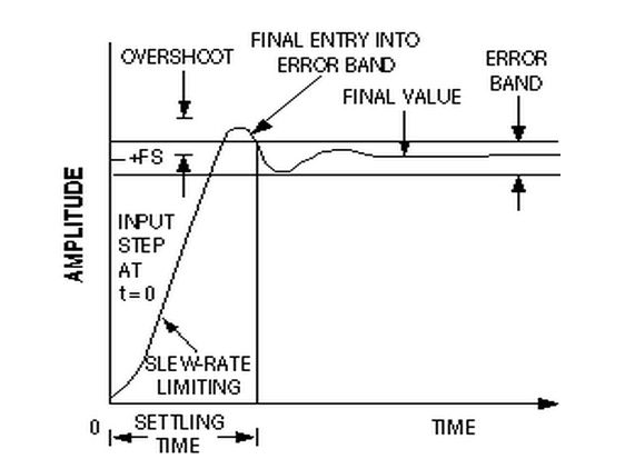
The Problem -- Derivative Kick
This modification is going to tweak the derivative term a bit.
The goal is to eliminate a phenomenon known as “Derivative Kick”.
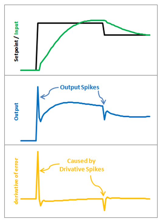
The image above illustrates the problem.
Since error=Setpoint-Input, any change in Setpoint causes an instantaneous change in error.
The derivative of this change is infinity (in practice, since dt isn’t 0 it just winds up being a really big number.)
This number gets fed into the pid equation, which results in an undesirable spike in the output.
Luckily there is an easy way to get rid of this.
The Solution
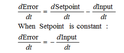
It turns out that the derivative of the Error is equal to negative derivative of Input, EXCEPT when the Setpoint is changing.
This winds up being a perfect solution.
Instead of adding (Kd * derivative of Error), we subtract (Kd * derivative of Input).
This is known as using “Derivative on Measurement”
/*working variables*/
unsigned long lastTime;
double Input, Output, Setpoint;
double errSum, lastInput;
double kp, ki, kd;
int SampleTime = 1000; //1 sec
void Compute()
{
   unsigned long now = millis();
   int timeChange = (now - lastTime);
   if(timeChange>=SampleTime)
   {
      /*Compute all the working error variables*/
      double error = Setpoint - Input;
      errSum += error;
      double dInput = (Input - lastInput);

      /*Compute PID Output*/
      Output = kp * error + ki * errSum - kd * dInput;

      /*Remember some variables for next time*/
      lastInput = Input;
      lastTime = now;
   }
}

void SetTunings(double Kp, double Ki, double Kd)
{
  double SampleTimeInSec = ((double)SampleTime)/1000;
   kp = Kp;
   ki = Ki * SampleTimeInSec;
   kd = Kd / SampleTimeInSec;
}

void SetSampleTime(int NewSampleTime)
{
   if (NewSampleTime > 0)
   {
      double ratio  = (double)NewSampleTime
                      / (double)SampleTime;
      ki *= ratio;
      kd /= ratio;
      SampleTime = (unsigned long)NewSampleTime;
   }
}
The modifications here are pretty easy.
We’re replacing +dError with -dInput.
Instead of remembering the lastError, we now remember the lastInput
The Result
Here’s what those modifications get us. Notice that the input still looks about the same.
So we get the same performance, but we don’t send out a huge Output spike every time the Setpoint changes.
This may or may not be a big deal.
It all depends on how sensitive your application is to output spikes.
The way I see it though, it doesn’t take any more work to do it without kicking so why not do things right?
The Problem -- Tuning Changes
The ability to change tuning parameters while the system is running is a must for any respectable PID algorithm.
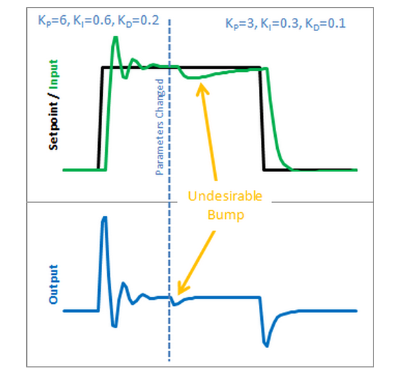
The Beginner’s PID acts a little crazy if you try to change the tunings while it’s running.
Let’s see why.
Here is the state of the beginner’s PID before and after the parameter change above:
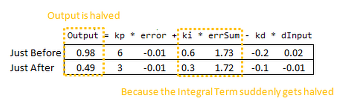
So we can immediately blame this bump on the Integral Term (or “I Term”).
It’s the only thing that changes drastically when the parameters change.
Why did this happen? It has to do with the beginner’s interpretation of the Integral:

This interpretation works fine until the Ki is changed.
Then, all of a sudden, you multiply this new Ki times the entire error sum that you have accumulated.
That’s not what we wanted! We only wanted to affect things moving forward!
The Solution
There are a couple ways I know of to deal with this problem.
The method I used in the last library was to rescale errSum.
Ki doubled?
Cut errSum in Half.
That keeps the I Term from bumping, and it works.
It’s kind of clunky though, and I’ve come up with something more elegant.
(There’s no way I’m the first to have thought of this, but I did think of it on my own. That counts damnit!)
The solution requires a little basic algebra (or is it calculus?)
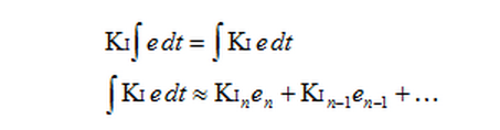
Instead of having the Ki live outside the integral, we bring it inside.
It looks like we haven’t done anything, but we’ll see that in practice this makes a big difference.
Now, we take the error and multiply it by whatever the Ki is at that time.
We then store the sum of THAT.
When the Ki changes, there’s no bump because all the old Ki’s are already “in the bank” so to speak.
We get a smooth transfer with no additional math operations.
It may make me a geek but I think that’s pretty sexy.
The Code
 1 /*working variables*/
 2 unsigned long lastTime;
 3 double Input, Output, Setpoint;
 4 double ITerm, lastInput;
 5 double kp, ki, kd;
 6 int SampleTime = 1000; //1 sec
 7 void Compute()
 8 {
 9    unsigned long now = millis();
10    int timeChange = (now - lastTime);
11    if(timeChange>=SampleTime)
12    {
13       /*Compute all the working error variables*/
14       double error = Setpoint - Input;
15       ITerm += (ki * error);
16       double dInput = (Input - lastInput);
17
18       /*Compute PID Output*/
19       Output = kp * error + ITerm - kd * dInput;
20
21       /*Remember some variables for next time*/
22       lastInput = Input;
23       lastTime = now;
24    }
25 }
26
27 void SetTunings(double Kp, double Ki, double Kd)
28 {
29   double SampleTimeInSec = ((double)SampleTime)/1000;
30    kp = Kp;
31    ki = Ki * SampleTimeInSec;
32    kd = Kd / SampleTimeInSec;
33 }
34
35 void SetSampleTime(int NewSampleTime)
36 {
37    if (NewSampleTime > 0)
38    {
39       double ratio  = (double)NewSampleTime
40                       / (double)SampleTime;
41       ki *= ratio;
42       kd /= ratio;
43       SampleTime = (unsigned long)NewSampleTime;
44    }
45 }
So we replaced the errSum variable with a composite ITerm variable [Line 4].
It sums Ki*error, rather than just error [Line 15].
Also, because Ki is now buried in ITerm, it’s removed from the main PID calculation [Line 19].
The Result

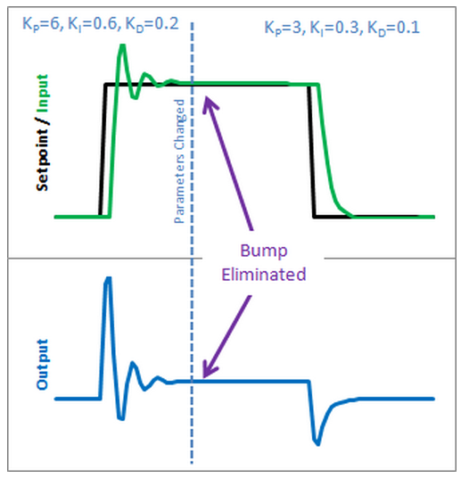
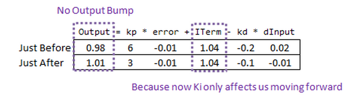
So how does this fix things.
Before when ki was changed, it rescaled the entire sum of the error; every error value we had seen.
With this code, the previous error remains untouched,
and the new ki only affects things moving forward, which is exactly what we want.
The Problem -- Reset Windup
Reset windup is a trap that probably claims more beginners than any other.
It occurs when the PID thinks it can do something that it can’t.
For example, the PWM output on an Arduino accepts values from 0-255.
By default the PID doesn’t know this.
If it thinks that 300-400-500 will work, it’s going to try those values expecting to get what it needs.
Since in reality the value is clamped at 255 it’s just going to keep trying higher
and higher numbers without getting anywhere.
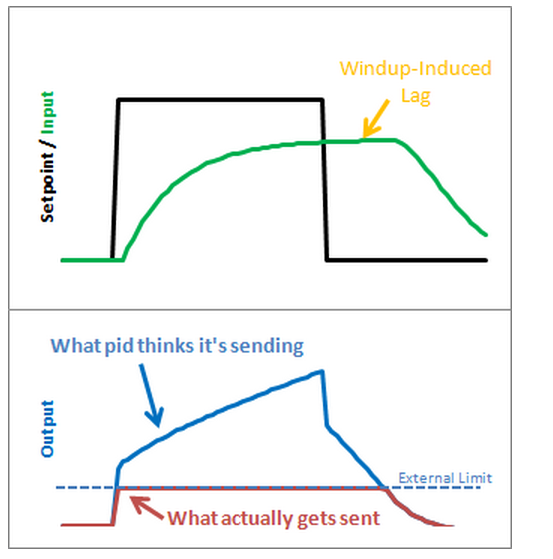
The problem reveals itself in the form of weird lags.
Above we can see that the output gets “wound up” WAY above the external limit.
When the setpoint is dropped the output has to wind down before getting below that 255-line.
The Solution – Step 1

There are several ways that windup can be mitigated, but the one that I chose was as follows:
tell the PID what the output limits are.
In the code below you’ll see there’s now a SetOuputLimits function.
Once either limit is reached, the pid stops summing (integrating.)
It knows there’s nothing to be done;
Since the output doesn’t wind-up, we get an immediate response
when the setpoint drops into a range where we can do something.
The Solution – Step 2
Notice in the graph above though, that while we got rid that windup lag, we’re not all the way there.
There’s still a difference between what the pid thinks it’s sending, and what’s being sent.
Why? the Proportional Term and (to a lesser extent) the Derivative Term.
Even though the Integral Term has been safely clamped, P and D are still adding their two cents,
yielding a result higher than the output limit.
To my mind this is unacceptable.
If the user calls a function called “SetOutputLimits” they’ve got to assume that that means
“the output will stay within these values.”
So for Step 2, we make that a valid assumption.
In addition to clamping the I-Term, we clamp the Output value so that it stays where we’d expect it.
(Note: You might ask why we need to clamp both.
If we’re going to do the output anyway, why clamp the Integral separately?
If all we did was clamp the output, the Integral term would go back to growing and growing.
Though the output would look nice during the step up, we’d see that telltale lag on the step down.)
 1 /*working variables*/
 2 unsigned long lastTime;
 3 double Input, Output, Setpoint;
 4 double ITerm, lastInput;
 5 double kp, ki, kd;
 6 int SampleTime = 1000; //1 sec
 7 double outMin, outMax;
 8 void Compute()
 9 {
10    unsigned long now = millis();
11    int timeChange = (now - lastTime);
12    if(timeChange>=SampleTime)
13    {
14       /*Compute all the working error variables*/
15       double error = Setpoint - Input;
16       ITerm+= (ki * error);
17       if(ITerm> outMax) ITerm= outMax;
18       else if(ITerm< outMin) ITerm= outMin;
19       double dInput = (Input - lastInput);
20
21       /*Compute PID Output*/
22       Output = kp * error + ITerm- kd * dInput;
23       if(Output > outMax) Output = outMax;
24       else if(Output < outMin) Output = outMin;
25
26       /*Remember some variables for next time*/
27       lastInput = Input;
28       lastTime = now;
29    }
30 }
31
32 void SetTunings(double Kp, double Ki, double Kd)
33 {
34   double SampleTimeInSec = ((double)SampleTime)/1000;
35    kp = Kp;
36    ki = Ki * SampleTimeInSec;
37    kd = Kd / SampleTimeInSec;
38 }
39
40 void SetSampleTime(int NewSampleTime)
41 {
42    if (NewSampleTime > 0)
43    {
44       double ratio  = (double)NewSampleTime
45                       / (double)SampleTime;
46       ki *= ratio;
47       kd /= ratio;
48       SampleTime = (unsigned long)NewSampleTime;
49    }
50 }
51
52 void SetOutputLimits(double Min, double Max)
53 {
54    if(Min > Max) return;
55    outMin = Min;
56    outMax = Max;
57
58    if(Output > outMax) Output = outMax;
59    else if(Output < outMin) Output = outMin;
60
61    if(ITerm> outMax) ITerm= outMax;
62    else if(ITerm< outMin) ITerm= outMin;
63 }
A new function was added to allow the user to specify the output limits [lines 52-63].
And these limits are used to clamp both the I-Term [17-18] and the Output [23-24]
The Result

As we can see, windup is eliminated.
in addition, the output stays where we want it to.
this means there’s no need for external clamping of the output.
if you want it to range from 23 to 167, you can set those as the Output Limits.
The Problem -- On/Off
As nice as it is to have a PID controller, sometimes you don’t care what it has to say.
Let’s say at some point in your program you want to force the output to a certain value (0 for example)
you could certainly do this in the calling routine:
void loop()
{
  Compute();
  Output=0;
}
This way, no matter what the PID says, you just overwrite its value.
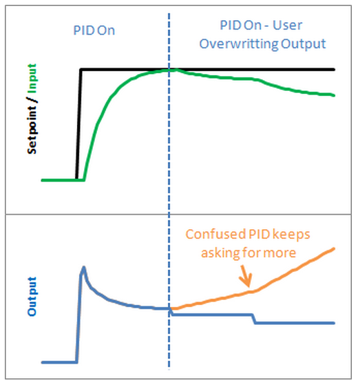
This is a terrible idea in practice however.
The PID will become very confused:
“I keep moving the output, and nothing’s happening! What gives?! Let me move it some more.”
As a result, when you stop over-writing the output and switch back to the PID,
you will likely get a huge and immediate change in the output value.
The Solution
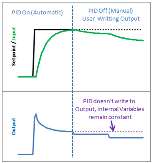
The solution to this problem is to have a means to turn the PID off and on.
The common terms for these states are “Manual” (I will adjust the value by hand)
and “Automatic” (the PID will automatically adjust the output).
Let’s see how this is done in code:
The Code
 1 /*working variables*/
 2 unsigned long lastTime;
 3 double Input, Output, Setpoint;
 4 double ITerm, lastInput;
 5 double kp, ki, kd;
 6 int SampleTime = 1000; //1 sec
 7 double outMin, outMax;
 8 bool inAuto = false;
 9
10 #define MANUAL 0
11 #define AUTOMATIC 1
12
13 void Compute()
14 {
15    if(!inAuto) return;
16    unsigned long now = millis();
17    int timeChange = (now - lastTime);
18    if(timeChange>=SampleTime)
19    {
20       /*Compute all the working error variables*/
21       double error = Setpoint - Input;
22       ITerm+= (ki * error);
23       if(ITerm> outMax) ITerm= outMax;
24       else if(ITerm< outMin) ITerm= outMin;
25       double dInput = (Input - lastInput);
26
27       /*Compute PID Output*/
28       Output = kp * error + ITerm- kd * dInput;
29       if(Output > outMax) Output = outMax;
30       else if(Output < outMin) Output = outMin;
31
32       /*Remember some variables for next time*/
33       lastInput = Input;
34       lastTime = now;
35    }
36 }
37
38 void SetTunings(double Kp, double Ki, double Kd)
39 {
40   double SampleTimeInSec = ((double)SampleTime)/1000;
41    kp = Kp;
42    ki = Ki * SampleTimeInSec;
43    kd = Kd / SampleTimeInSec;
44 }
45
46 void SetSampleTime(int NewSampleTime)
47 {
48    if (NewSampleTime > 0)
49    {
50       double ratio  = (double)NewSampleTime
51                       / (double)SampleTime;
52       ki *= ratio;
53       kd /= ratio;
54       SampleTime = (unsigned long)NewSampleTime;
55    }
56 }
57
58 void SetOutputLimits(double Min, double Max)
59 {
60    if(Min > Max) return;
61    outMin = Min;
62    outMax = Max;
63
64    if(Output > outMax) Output = outMax;
65    else if(Output < outMin) Output = outMin;
66
67    if(ITerm> outMax) ITerm= outMax;
68    else if(ITerm< outMin) ITerm= outMin;
69 }
70
71 void SetMode(int Mode)
72 {
73   inAuto = (Mode == AUTOMATIC);
74 }
A fairly simple solution. If you’re not in automatic mode,
immediately leave the Compute function without adjusting the Output or any internal variables.
The Result
It’s true that you could achieve a similar effect by just not calling Compute from the calling routine,
but this solution keeps the workings of the PID contained, which is kind of what we need.
By keeping things internal we can keep track of which mode were in,
and more importantly it let’s us know when we change modes. That leads us to the next issue…
The Problem -- Initialization
In the last section we implemented the ability to turn the PID off and on.
We turned it off, but now let’s look at what happens when we turn it back on:
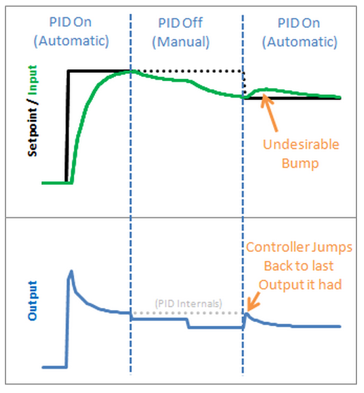
Yikes! The PID jumps back to the last Output value it sent, then starts adjusting from there.
This results in an Input bump that we’d rather not have.
The Solution
This one is pretty easy to fix. Since we now know when we’re turning on (going from Manual to Automatic,) we just have to initialize things for a smooth transition. That means massaging the 2 stored working variables (ITerm & lastInput) to keep the output from jumping.
The Code
 1 /*working variables*/
 2 unsigned long lastTime;
 3 double Input, Output, Setpoint;
 4 double ITerm, lastInput;
 5 double kp, ki, kd;
 6 int SampleTime = 1000; //1 sec
 7 double outMin, outMax;
 8 bool inAuto = false;
 9
10 #define MANUAL 0
11 #define AUTOMATIC 1
12
13 void Compute()
14 {
15    if(!inAuto) return;
16    unsigned long now = millis();
17    int timeChange = (now - lastTime);
18    if(timeChange>=SampleTime)
19    {
20       /*Compute all the working error variables*/
21       double error = Setpoint - Input;
22       ITerm+= (ki * error);
23       if(ITerm> outMax) ITerm= outMax;
24       else if(ITerm< outMin) ITerm= outMin;
25       double dInput = (Input - lastInput);
26
27       /*Compute PID Output*/
28       Output = kp * error + ITerm- kd * dInput;
29       if(Output> outMax) Output = outMax;
30       else if(Output < outMin) Output = outMin;
31
32       /*Remember some variables for next time*/
33       lastInput = Input;
34       lastTime = now;
35    }
36 }
37
38 void SetTunings(double Kp, double Ki, double Kd)
39 {
40   double SampleTimeInSec = ((double)SampleTime)/1000;
41    kp = Kp;
42    ki = Ki * SampleTimeInSec;
43    kd = Kd / SampleTimeInSec;
44 }
45
46 void SetSampleTime(int NewSampleTime)
47 {
48    if (NewSampleTime > 0)
49    {
50       double ratio  = (double)NewSampleTime
51                       / (double)SampleTime;
52       ki *= ratio;
53       kd /= ratio;
54       SampleTime = (unsigned long)NewSampleTime;
55    }
56 }
57
58 void SetOutputLimits(double Min, double Max)
59 {
60    if(Min > Max) return;
61    outMin = Min;
62    outMax = Max;
63
64    if(Output > outMax) Output = outMax;
65    else if(Output < outMin) Output = outMin;
66
67    if(ITerm> outMax) ITerm= outMax;
68    else if(ITerm< outMin) ITerm= outMin;
69 }
70
71 void SetMode(int Mode)
72 {
73     bool newAuto = (Mode == AUTOMATIC);
74     if(newAuto && !inAuto)
75     {  /*we just went from manual to auto*/
76         Initialize();
77     }
78     inAuto = newAuto;
79 }
80
81 void Initialize()
82 {
83    lastInput = Input;
84    ITerm = Output;
85    if(ITerm> outMax) ITerm= outMax;
86    else if(ITerm< outMin) ITerm= outMin;
87 }
We modified SetMode(…) to detect the transition from manual to automatic,
and we added our initialization function.
It sets ITerm=Output to take care of the integral term, and lastInput = Input to keep the derivative from spiking.
The proportional term doesn’t rely on any information from the past, so it doesn’t need any initialization.
The Result
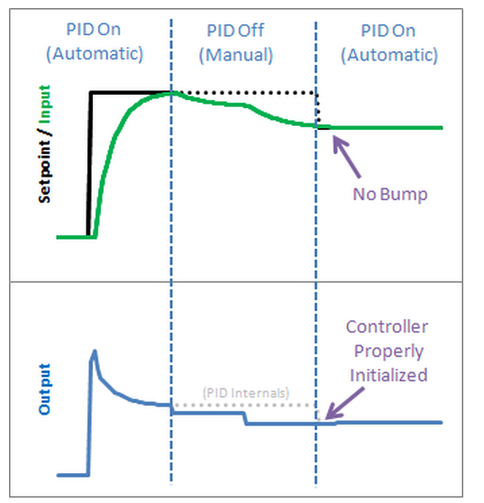
We see from the above graph that proper initialization results in a bumpless transfer from manual to automatic: exactly what we were after
Update: Why not ITerm=0?
I have been getting a lot of questions recently asking why I don’t set ITerm=0 upon intialization.
As an answer, I’d ask you to consider the following scenario:
The pid is in manual, and the user has set the output to 50.
After a time, the process steadies out to an input of 75.2.
The user makes the Setpoint 75.2 and turns on the pid. What should happen?
I contend that after switching to automatic the output value should stay at 50.
since the P and D terms will be zero, the only way this will happen is if ITerm is initialized to the value of Output.
If you are in a situation where you need the output to initialize to zero, there is no need alter the code above.
Just set Output=0 in your calling routine before turning the PID from Manual to Automatic.
The Problem -- Direction
The processes the PID will be connected to fall into two groups: direct acting and reverse acting. All the examples I’ve shown so far have been direct acting. That is, an increase in the output causes an increase in the input. For reverse acting processes the opposite is true. In a refrigerator for example, an increase in cooling causes the temperature to go down. To make the beginner PID work with a reverse process, the signs of kp, ki, and kd all must be negative.
This isn’t a problem per se, but the user must choose the correct sign, and make sure that all the parameters have the same sign.
The Solution
To make the process a little simpler, I require that kp, ki, and kd all be >=0. If the user is connected to a reverse process, they specify that separately using the SetControllerDirection function. this ensures that the parameters all have the same sign, and hopefully makes things more intuitive.
The Code
  1 /*working variables*/
  2 unsigned long lastTime;
  3 double Input, Output, Setpoint;
  4 double ITerm, lastInput;
  5 double kp, ki, kd;
  6 int SampleTime = 1000; //1 sec
  7 double outMin, outMax;
  8 bool inAuto = false;
  9
 10 #define MANUAL 0
 11 #define AUTOMATIC 1
 12
 13 #define DIRECT 0
 14 #define REVERSE 1
 15 int controllerDirection = DIRECT;
 16
 17 void Compute()
 18 {
 19    if(!inAuto) return;
 20    unsigned long now = millis();
 21    int timeChange = (now - lastTime);
 22    if(timeChange>=SampleTime)
 23    {
 24       /*Compute all the working error variables*/
 25       double error = Setpoint - Input;
 26       ITerm+= (ki * error);
 27       if(ITerm > outMax) ITerm= outMax;
 28       else if(ITerm < outMin) ITerm= outMin;
 29       double dInput = (Input - lastInput);
 30
 31       /*Compute PID Output*/
 32       Output = kp * error + ITerm- kd * dInput;
 33       if(Output > outMax) Output = outMax;
 34       else if(Output < outMin) Output = outMin;
 35
 36       /*Remember some variables for next time*/
 37       lastInput = Input;
 38       lastTime = now;
 39    }
 40 }
 41
 42 void SetTunings(double Kp, double Ki, double Kd)
 43 {
 44    if (Kp<0 || Ki<0|| Kd<0) return;
 45
 46   double SampleTimeInSec = ((double)SampleTime)/1000;
 47    kp = Kp;
 48    ki = Ki * SampleTimeInSec;
 49    kd = Kd / SampleTimeInSec;
 50
 51   if(controllerDirection ==REVERSE)
 52    {
 53       kp = (0 - kp);
 54       ki = (0 - ki);
 55       kd = (0 - kd);
 56    }
 57 }
 58
 59 void SetSampleTime(int NewSampleTime)
 60 {
 61    if (NewSampleTime > 0)
 62    {
 63       double ratio  = (double)NewSampleTime
 64                       / (double)SampleTime;
 65       ki *= ratio;
 66       kd /= ratio;
 67       SampleTime = (unsigned long)NewSampleTime;
 68    }
 69 }
 70
 71 void SetOutputLimits(double Min, double Max)
 72 {
 73    if(Min > Max) return;
 74    outMin = Min;
 75    outMax = Max;
 76
 77    if(Output > outMax) Output = outMax;
 78    else if(Output < outMin) Output = outMin;
 79
 80    if(ITerm > outMax) ITerm= outMax;
 81    else if(ITerm < outMin) ITerm= outMin;
 82 }
 83
 84 void SetMode(int Mode)
 85 {
 86     bool newAuto = (Mode == AUTOMATIC);
 87     if(newAuto == !inAuto)
 88     {  /*we just went from manual to auto*/
 89         Initialize();
 90     }
 91     inAuto = newAuto;
 92 }
 93
 94 void Initialize()
 95 {
 96    lastInput = Input;
 97    ITerm = Output;
 98    if(ITerm > outMax) ITerm= outMax;
 99    else if(ITerm < outMin) ITerm= outMin;
100 }
101
102 void SetControllerDirection(int Direction)
103 {
104    controllerDirection = Direction;
105 }
PID COMPLETE
And that about wraps it up.
We’ve turned “The Beginner’s PID” into the most robust controller I know how to make at this time.
For those readers that were looking for a detailed explanation of the PID Library,
I hope you got what you came for. For those of you writing your own PID,
I hope you were able to glean a few ideas that save you some cycles down the road.
Two Final Notes:
- If something in this series looks wrong please let me know.
I may have missed something, or might just need to be clearer in my explanation.
Either way I’d like to know. - This is just a basic PID. There are many other issues that I intentionally left out in the name of simplicity.
Off the top of my head: feed forward, reset tiebacks, integer math, different pid forms, using velocity instead of position.
If there’s interest in having me explore these topics please let me know.
DOWNLOAD
PID Library
PID Front-End using Processing.org
- Latest version: v0.3
Older Versions can be viewed / downloaded here
THE BASICS
What Is PID?
From Wikipedia: "A PID controller calculates an 'error' value as the difference between a measured [Input] and a desired setpoint. The controller attempts to minimize the error by adjusting [an Output]."
So, you tell the PID what to measure (the "Input",) Where you want that measurement to be (the "Setpoint",) and the variable to adjust that can make that happen (the "Output".) The PID then adjusts the output trying to make the input equal the setpoint.
For reference, in a car, the Input, Setpoint, and Output would be the speed, desired speed, and gas pedal angle respectively.
Tuning Parameters
The black magic of PID comes in when we talk about HOW it adjusts the Output to drive the Input towards Setpoint. There are 3 Tuning Parameters (or "Tunings"): Kp, Ki & Kd. Adjusting these values will change the way the output is adjusted. Fast? Slow? God-awful? All of these can be achieved depending on the values of Kp, Ki, and Kd.
So what are the "right" tuning values to use? There isn't one right answer. The values that work for one application may not work for another, just as the driving style that works for a truck may not work for a race car. With each new application you will need to try Several Tuning values until you find a set that gives you what you want.
Note: there is also now a PID Autotune Library that can help you determine tuning parameters.
Should I Use PID?
PID is a pretty impressive control algorithm, but it's not magic. You should at least be able to answer "yes" to these questions:
- Is it worth the extra work? If you're using a more basic system and it's working for you, there's no real reason to use PID.
- Is your system repeatable? The PID needs some semblance of repeatability. When the output is changed from A to B, at least roughly the same thing should happen every time. (think of a car where you step on the gas and sometimes you speed up and sometimes you slow down. not repeatable, not a place where you could use PID)
(This list will probably grow as I think of more criteria. These are the big ones though)
A Note About Relays
Even though a PID controller is designed to work with an analog output, it is possible to connect to a discrete output such as a relay. Be sure to look at the RelayOutput example below.
Questions?
Try the newly created Google group.
The Library
Using The PID Library has two benefits in my mind
- There are many ways to write the PID algorithm. A lot of time was spent making the algorithm in this library as solid as any found in industry. If you want to read more about this, check out this detailed explanation.
- When using the library all the PID code is self-contained. This makes your code easier to understand. It also lets you do more complex stuff, like say having 8 PIDs in the same program.
Functions
Examples
***************************************************************
* Arduino PID Library - Version 1.1.1
* by Brett Beauregard <br3ttb@gmail.com> brettbeauregard.com
*
* This Library is licensed under a GPLv3 License
***************************************************************
- For an ultra-detailed explanation of why the code is the way it is, please visit:
http://brettbeauregard.com/blog/2011/04/improving-the-beginners-pid-introduction/
- For function documentation see: http://playground.arduino.cc/Code/PIDLibrary
#ifndef PID_v1_h
#define PID_v1_h
#define LIBRARY_VERSION    1.1.1

class PID
{


  public:

  //Constants used in some of the functions below
  #define AUTOMATIC    1
  #define MANUAL    0
  #define DIRECT  0
  #define REVERSE  1

  //commonly used functions **************************************************************************
    PID(double*, double*, double*,        // * constructor.  links the PID to the Input, Output, and
        double, double, double, int);     //   Setpoint.  Initial tuning parameters are also set here

    void SetMode(int Mode);               // * sets PID to either Manual (0) or Auto (non-0)

    bool Compute();                       // * performs the PID calculation.  it should be
                                          //   called every time loop() cycles. ON/OFF and
                                          //   calculation frequency can be set using SetMode
                                          //   SetSampleTime respectively

    void SetOutputLimits(double, double); //clamps the output to a specific range. 0-255 by default, but
                                          //it's likely the user will want to change this depending on
                                          //the application


  //available but not commonly used functions ********************************************************
    void SetTunings(double, double,       // * While most users will set the tunings once in the
                    double);               //   constructor, this function gives the user the option
                                          //   of changing tunings during runtime for Adaptive control
    void SetControllerDirection(int);      // * Sets the Direction, or "Action" of the controller. DIRECT
                                          //   means the output will increase when error is positive. REVERSE
                                          //   means the opposite.  it's very unlikely that this will be needed
                                          //   once it is set in the constructor.
    void SetSampleTime(int);              // * sets the frequency, in Milliseconds, with which
                                          //   the PID calculation is performed.  default is 100


  //Display functions ****************************************************************
    double GetKp();                          // These functions query the pid for interal values.
    double GetKi();                          //  they were created mainly for the pid front-end,
    double GetKd();                          // where it's important to know what is actually
    int GetMode();                          //  inside the PID.
    int GetDirection();                      //

  private:
    void Initialize();

    double dispKp;                // * we'll hold on to the tuning parameters in user-entered
    double dispKi;                //   format for display purposes
    double dispKd;                //

    double kp;                  // * (P)roportional Tuning Parameter
    double ki;                  // * (I)ntegral Tuning Parameter
    double kd;                  // * (D)erivative Tuning Parameter

    int controllerDirection;

    double *myInput;              // * Pointers to the Input, Output, and Setpoint variables
    double *myOutput;             //   This creates a hard link between the variables and the
    double *mySetpoint;           //   PID, freeing the user from having to constantly tell us
                                  //   what these values are.  with pointers we'll just know.

    unsigned long lastTime;
    double ITerm, lastInput;

    unsigned long SampleTime;
    double outMin, outMax;
    bool inAuto;
};
#endif
/**********************************************************************************************
 * Arduino PID Library - Version 1.1.1
 * by Brett Beauregard <br3ttb@gmail.com> brettbeauregard.com
 *
 * This Library is licensed under a GPLv3 License
 **********************************************************************************************/

#if ARDUINO >= 100
  #include "Arduino.h"
#else
  #include "WProgram.h"
#endif

#include <PID_v1.h>

/*Constructor (...)*********************************************************
 *    The parameters specified here are those for for which we can't set up
 *    reliable defaults, so we need to have the user set them.
 ***************************************************************************/
PID::PID(double* Input, double* Output, double* Setpoint,
        double Kp, double Ki, double Kd, int ControllerDirection)
{

    myOutput = Output;
    myInput = Input;
    mySetpoint = Setpoint;
    inAuto = false;

    PID::SetOutputLimits(0, 255);                //default output limit corresponds to
                                                //the arduino pwm limits

    SampleTime = 100;                            //default Controller Sample Time is 0.1 seconds

    PID::SetControllerDirection(ControllerDirection);
    PID::SetTunings(Kp, Ki, Kd);

    lastTime = millis()-SampleTime;
}


/* Compute() **********************************************************************
 *     This, as they say, is where the magic happens.  this function should be called
 *   every time "void loop()" executes.  the function will decide for itself whether a new
 *   pid Output needs to be computed.  returns true when the output is computed,
 *   false when nothing has been done.
 **********************************************************************************/
bool PID::Compute()
{
   if(!inAuto) return false;
   unsigned long now = millis();
   unsigned long timeChange = (now - lastTime);
   if(timeChange>=SampleTime)
   {
      /*Compute all the working error variables*/
      double input = *myInput;
      double error = *mySetpoint - input;
      ITerm+= (ki * error);
      if(ITerm > outMax) ITerm= outMax;
      else if(ITerm < outMin) ITerm= outMin;
      double dInput = (input - lastInput);

      /*Compute PID Output*/
      double output = kp * error + ITerm- kd * dInput;

      if(output > outMax) output = outMax;
      else if(output < outMin) output = outMin;
      *myOutput = output;

      /*Remember some variables for next time*/
      lastInput = input;
      lastTime = now;
      return true;
   }
   else return false;
}


/* SetTunings(...)*************************************************************
 * This function allows the controller's dynamic performance to be adjusted.
 * it's called automatically from the constructor, but tunings can also
 * be adjusted on the fly during normal operation
 ******************************************************************************/
void PID::SetTunings(double Kp, double Ki, double Kd)
{
   if (Kp<0 || Ki<0 || Kd<0) return;

   dispKp = Kp; dispKi = Ki; dispKd = Kd;

   double SampleTimeInSec = ((double)SampleTime)/1000;
   kp = Kp;
   ki = Ki * SampleTimeInSec;
   kd = Kd / SampleTimeInSec;

  if(controllerDirection ==REVERSE)
   {
      kp = (0 - kp);
      ki = (0 - ki);
      kd = (0 - kd);
   }
}

/* SetSampleTime(...) *********************************************************
 * sets the period, in Milliseconds, at which the calculation is performed
 ******************************************************************************/
void PID::SetSampleTime(int NewSampleTime)
{
   if (NewSampleTime > 0)
   {
      double ratio  = (double)NewSampleTime
                      / (double)SampleTime;
      ki *= ratio;
      kd /= ratio;
      SampleTime = (unsigned long)NewSampleTime;
   }
}

/* SetOutputLimits(...)****************************************************
 *     This function will be used far more often than SetInputLimits.  while
 *  the input to the controller will generally be in the 0-1023 range (which is
 *  the default already,)  the output will be a little different.  maybe they'll
 *  be doing a time window and will need 0-8000 or something.  or maybe they'll
 *  want to clamp it from 0-125.  who knows.  at any rate, that can all be done
 *  here.
 **************************************************************************/
void PID::SetOutputLimits(double Min, double Max)
{
   if(Min >= Max) return;
   outMin = Min;
   outMax = Max;

   if(inAuto)
   {
       if(*myOutput > outMax) *myOutput = outMax;
       else if(*myOutput < outMin) *myOutput = outMin;

       if(ITerm > outMax) ITerm= outMax;
       else if(ITerm < outMin) ITerm= outMin;
   }
}

/* SetMode(...)****************************************************************
 * Allows the controller Mode to be set to manual (0) or Automatic (non-zero)
 * when the transition from manual to auto occurs, the controller is
 * automatically initialized
 ******************************************************************************/
void PID::SetMode(int Mode)
{
    bool newAuto = (Mode == AUTOMATIC);
    if(newAuto == !inAuto)
    {  /*we just went from manual to auto*/
        PID::Initialize();
    }
    inAuto = newAuto;
}

/* Initialize()****************************************************************
 *    does all the things that need to happen to ensure a bumpless transfer
 *  from manual to automatic mode.
 ******************************************************************************/
void PID::Initialize()
{
   ITerm = *myOutput;
   lastInput = *myInput;
   if(ITerm > outMax) ITerm = outMax;
   else if(ITerm < outMin) ITerm = outMin;
}

/* SetControllerDirection(...)*************************************************
 * The PID will either be connected to a DIRECT acting process (+Output leads
 * to +Input) or a REVERSE acting process(+Output leads to -Input.)  we need to
 * know which one, because otherwise we may increase the output when we should
 * be decreasing.  This is called from the constructor.
 ******************************************************************************/
void PID::SetControllerDirection(int Direction)
{
   if(inAuto && Direction !=controllerDirection)
   {
      kp = (0 - kp);
      ki = (0 - ki);
      kd = (0 - kd);
   }
   controllerDirection = Direction;
}

/* Status Funcions*************************************************************
 * Just because you set the Kp=-1 doesn't mean it actually happened.  these
 * functions query the internal state of the PID.  they're here for display
 * purposes.  this are the functions the PID Front-end uses for example
 ******************************************************************************/
double PID::GetKp(){ return  dispKp; }
double PID::GetKi(){ return  dispKi;}
double PID::GetKd(){ return  dispKd;}
int PID::GetMode(){ return  inAuto ? AUTOMATIC : MANUAL;}
int PID::GetDirection(){ return controllerDirection;}
Example
/********************************************************
 * PID Basic Example
 * Reading analog input 0 to control analog PWM output 3
 ********************************************************/

#include <PID_v1.h>

#define PIN_INPUT 0
#define PIN_OUTPUT 3

//Define Variables we'll be connecting to
double Setpoint, Input, Output;

//Specify the links and initial tuning parameters
double Kp=2, Ki=5, Kd=1;
PID myPID(&Input, &Output, &Setpoint, Kp, Ki, Kd, DIRECT);

void setup()
{
  //initialize the variables we're linked to
  Input = analogRead(PIN_INPUT);
  Setpoint = 100;

  //turn the PID on
  myPID.SetMode(AUTOMATIC);
}

void loop()
{
  Input = analogRead(PIN_INPUT);
  myPID.Compute();
  analogWrite(PIN_OUTPUT, Output);
}
/********************************************************
 * PID Adaptive Tuning Example
 * One of the benefits of the PID library is that you can
 * change the tuning parameters at any time.  this can be
 * helpful if we want the controller to be agressive at some
 * times, and conservative at others.   in the example below
 * we set the controller to use Conservative Tuning Parameters
 * when we're near setpoint and more agressive Tuning
 * Parameters when we're farther away.
 ********************************************************/

#include <PID_v1.h>

#define PIN_INPUT 0
#define PIN_OUTPUT 3

//Define Variables we'll be connecting to
double Setpoint, Input, Output;

//Define the aggressive and conservative Tuning Parameters
double aggKp=4, aggKi=0.2, aggKd=1;
double consKp=1, consKi=0.05, consKd=0.25;

//Specify the links and initial tuning parameters
PID myPID(&Input, &Output, &Setpoint, consKp, consKi, consKd, DIRECT);

void setup()
{
  //initialize the variables we're linked to
  Input = analogRead(PIN_INPUT);
  Setpoint = 100;

  //turn the PID on
  myPID.SetMode(AUTOMATIC);
}

void loop()
{
  Input = analogRead(PIN_INPUT);

  double gap = abs(Setpoint-Input); //distance away from setpoint
  if (gap < 10)
  {  //we're close to setpoint, use conservative tuning parameters
    myPID.SetTunings(consKp, consKi, consKd);
  }
  else
  {
     //we're far from setpoint, use aggressive tuning parameters
     myPID.SetTunings(aggKp, aggKi, aggKd);
  }

  myPID.Compute();
  analogWrite(PIN_OUTPUT, Output);
}
/********************************************************
 * PID RelayOutput Example
 * Same as basic example, except that this time, the output
 * is going to a digital pin which (we presume) is controlling
 * a relay.  the pid is designed to Output an analog value,
 * but the relay can only be On/Off.
 *
 *   to connect them together we use "time proportioning
 * control"  it's essentially a really slow version of PWM.
 * first we decide on a window size (5000mS say.) we then
 * set the pid to adjust its output between 0 and that window
 * size.  lastly, we add some logic that translates the PID
 * output into "Relay On Time" with the remainder of the
 * window being "Relay Off Time"
 ********************************************************/

#include <PID_v1.h>

#define PIN_INPUT 0
#define RELAY_PIN 6

//Define Variables we'll be connecting to
double Setpoint, Input, Output;

//Specify the links and initial tuning parameters
double Kp=2, Ki=5, Kd=1;
PID myPID(&Input, &Output, &Setpoint, Kp, Ki, Kd, DIRECT);

int WindowSize = 5000;
unsigned long windowStartTime;

void setup()
{
  windowStartTime = millis();

  //initialize the variables we're linked to
  Setpoint = 100;

  //tell the PID to range between 0 and the full window size
  myPID.SetOutputLimits(0, WindowSize);

  //turn the PID on
  myPID.SetMode(AUTOMATIC);
}

void loop()
{
  Input = analogRead(PIN_INPUT);
  myPID.Compute();

  /************************************************
   * turn the output pin on/off based on pid output
   ************************************************/
  if (millis() - windowStartTime > WindowSize)
  { //time to shift the Relay Window
    windowStartTime += WindowSize;
  }
  if (Output < millis() - windowStartTime) digitalWrite(RELAY_PIN, HIGH);
  else digitalWrite(RELAY_PIN, LOW);

}

