
反接保护电路 Reverse Voltage Protection
I've long wanted to pull together some reverse polarity protection ideas in one place.
Many are found individually on the web, but seldom several in one place.
A recent QRP-L thread prompted me to put together this page.
I haven't tried all of them, and none are original with me.
I'm just pulling together ideas from others. You're on your own for circuit and part selection.
Click on the pictures for a larger image if needed. Please email if you wish me to add a circuit,
have a comment about the page, or if you spot any errors. Thank you es 72 ... WAØITP
Blocking Diode
 |
|
Full Wave Rectifier
 |
|
P Channel MOSFET - PMOS
 |
|
Regulator - PNP or LDO
 |
|
Fuse and Diode
 |
|
Resettable Fuse
 |
|
Relay with NC Contacts
 |
|
Relay with NO Contacts
 |
|
NMOS with Specialized IC
 |
|
Anderson Power Poles
 |
|
Anderson Power Pole Checker
 |
|
Using MOSFETs as blocking diodes
Connecting a battery backwards to an electronic circuit can rapidly do a lot of damage — current will flood through (and destroy) many integrated circuits when powered up the wrong way, and electrolytic capacitors have a famous tendency to explode. For this reason, it’s common to use a blocking diode in a circuit to provide reverse polarity protection:
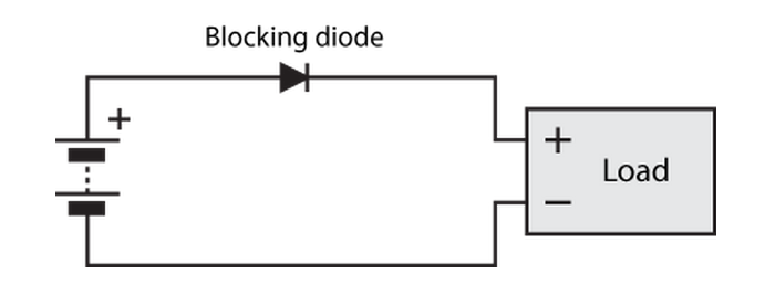
If the battery is connected correctly, as shown, current flows through the diode to the circuit, and the circuit operates normally. If the battery is reversed, the battery tries to pull current through the diode the wrong way, and the diode refuses to conduct — protecting the load from damage.
The diode can also be placed on the low rail, as shown below. This is completely equivalent to the circuit shown above for battery-powered applications. However, it may make less sense in circuit provided positive DC power by an external supply, where having a consistent ground can be important. On the flip side, a circuit that operates using negative DC power (which is much rarer) would be much better off with the circuit below for the same reason.

This blocking diode approach works great for many applications. However, when the diode is conducting, there is a voltage drop across it (typically around 0.7V for silicon diodes, 0.2V for Schottky diodes) which means that the load sees a bit less voltage across it. This is a particularly major problem for low voltage applications, where a 0.3V drop can represent almost 10% of a 3.3V system’s power, wasted at the very first component. For higher power applications, a fair bit of power can be wasted as heat in the diode as well.
An alternative solution: MOSFETs
The wonderful thing about MOSFETs is that they can be designed to have incredibly low voltage drops, which translates into less waste heat and more voltage for the load to operate. You can routinely get MOSFETs with resistances of 20 milliohms and below, which translates to allowing 5 amps to pass with a drop of only 0.1V, less than any diode.
You can’t just use them as a direct drop-in replacement, though, because you have to drive the gate of the MOSFET somehow. Here’s the trick: you can just use the other terminal of the battery for this:

So, how does this work? I’m going to define the voltage of the bottom net, 


At the instant that the battery is connected, 
It turns out that this design actually relies on the body diode to work, at least briefly. Current will flow through the body diode to the load, raising
When reverse biased, the body diode will be reverse biased, and will therefore not conduct.
An N-channel FET can be used on the bottom rail instead, like so:
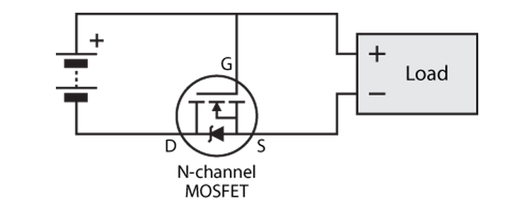
The same comments apply as for the aforementioned blocking diode on the bottom rail. There’s one additional advantage here, though: N-channel FETs tend to have better performance characteristics than P-channel FETs (although these days, both are remarkably excellent).
What’s the catch?
There are a number of reasons why this MOSFET circuit is not always a suitable replacement for a normal blocking diode:
- Some blocking diodes are used in applications where current from a generator is used to charge two separate batteries. If one battery ends up with a higher voltage than another, the blocking diodes prevent electricity from flowing out of the higher voltage battery, back onto the generator leads, and into the other battery. The circuit above will completely fail at this job, because
- It might not always be easy to physically connect the gate of the MOSFET to the opposite rail, especially with a circuit laid out with a normal diode in mind.
- MOSFETs have a few more maximum limits to check and look after than diode, owing mostly to the fact the a MOSFET has an extra leg. This isn’t a practical disadvantage, just something to be careful about.
Is it safe to pass current through the MOSFET in the non-conventional direction?
It might seem unusual to pass current up through the MOSFET, especially since the curves in datasheets don’t seem to cover this region. However, operation in this so-called third quadrant is routinely used in buck converters, where a MOSFET is used to replace the reverse recovery diode (source). The reasons for replacing the reverse recovery diode with a MOSFET are exactly the same as for replacing blocking diodes — it’s to avoid energy wasted due to diode voltage drop.
MOSFET selection
The figures below are for the P-FET design, N-FET design will be similar except with a few minus signs thrown around the place. This is just a rough guide, etc.
- The absolute maximum
should be at least
, where
is the voltage of the power supply/battery. This is because in a situation when correct polarity rapidly switches to reverse polarity, you get
,
.
- The absolute maximum
.
- Check the output characteristics to ensure that the FET is thoroughly on when
. Roughly speaking, this corresponds to
being greater than than
(remembering, e.g., –2 is greater than –9).
- And of course, check that the FET can handle the current, the power dissipated, and the heat generated. And yes, these are three related but very different things that need to be checked independently (the last is calculated using thermal resistance, given in the datasheet).
Fin.
So there you have it. If anyone out there uses this circuit because of this page, I’d love to hear about it! And as always, I will attend to any questions left below.

