
LDO current regulator for power LED
LDO current regulator for power LED
Challenge
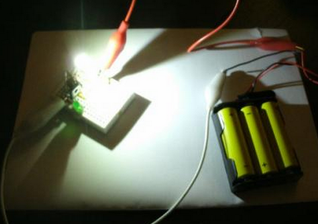
You've got a power LED? Great! Build a flash light!
What does the spec say? "Voltage: 3.6 .. 3.8 V, power 3 W." Okay. This means that it draws some 800 mA. Three mignon cells give 4.5 V for at least three hours. So we add a resistor of 1.2 Ohm and we are safe. If the LED runs at 3.6 V this gives 750 mA and 2.8 W while the resistor voltage is 0.9 V resulting in 0.675 W for the resistor. So we take a resistor that can stand 1 W. Simple, isn't it?
Yes and no. The LED in this simple circuit will glow but what happens if voltage drops because batteries go flat? If voltage drops by 10 % you'll get 4.05 V and current drops by some 50 % meaning that you need rather full batteries to get a reasonable amount of light from your LED. First idea is to put a voltage regulator between the batteries and the circuit and adapt the resistor to its output voltage. However, finding a suitable regulator is tricky. You need a low dropout voltage to let the LED work at full brightness when batteries voltage becomes low.
BJT Current Limiter
We can do better! To stabilize brightness we have to regulate the power consumption of the LED by controlling the current. Wikipedia [1] shows a simple circuit of two transistors and three resistors limiting current independent of supply voltage. We change this circuit by removing resistor R2 which is not really needed. What about dropout voltage? Clearly, there is VCEsat of Q2 which can be in the area of 0.2 V at current around 1 A (for BC640, BD13x, BD23x, BD43x...). However, there is the additional voltage of the emitter resistor which equals VBEon of Q1, typically some 0.7 .. 0.9 V. So we get a total dropout voltage of VBEon1 + VCEsat2 resulting in some 1.0 V.
This dropout voltage is too high for three mignon cells. If you are not keen on energy efficiency and ready to carry four mignon cells then you are done.
Rail to Rail Operational Amplifier
But we can do even more better! The two transistor current limiter is a control loop sensing the current by a resistor and keeping the voltage equal to VBE of a transistor. What about reducing this voltage? There are operational amplifiers with rail to rail input and output meaning that they can handle voltages from VSS to VDD. There are numerous such parts like the MC33201.
Have a look at this current limiter circuit in Wikipedia [2]. Voltage over the sense resistor is kept equal to voltage over z-diode. Okay, there are no z-diodes of really low voltage. Since the amplifier has high input impedance we can use a voltage regulator and simply reduce the voltage using a voltage divider.

One point still to notice is output current of the amplifier. If we use a BD139 transistor this will give us a current gain of 40 or more meaning that the amplifier has to deliver 20 mA which is okay for the MC33201. If the transistor needs higher base current than the amplifier can deliver we have to at an emitter follower between amplifier and transistor.
In our 3 W LED example we can use a resistor of 0.33 Ohm delivering a voltage of some 0.25 V in operation which can be handled by the op amp. Now add VCEsat of 0.2 V and get less than .5 V dropout. Okay, this is a little cheating becuse VCEsat would requires 80 mA which won't be delivered by an MC33201.
Dimming
Brightness can be controlled by reference voltage. Simply use a potentiometer as voltage divider. Or connect the amplifier input to another circuit like a multivibrator to flash the light or to some rectifier and low pass for a light organ.
Future Work
If we are controlling brightness using a mirocontroller with ADC and DAC or PWM we can even drop the Op Amp. Feedback voltage will be digitized by the ADC, then a PID program computes output voltage and DAC or PWM with RC low pass control power transistor. This gives opportunity for additional functionality like touch pad control, remote control, or automatices.
Using a MOSFET instead of a BJT might further reduce dropout voltage. For instance, MCP87xx have very low RDS and low threshold voltage making them suitable also for the microcontroller idea running the controller at 2 V or so.
Final Remarks
There is an instructable [3] showing how to build a power LED driver. This article mainly describes a discrete circuit similar to the two BJT circuit in [1] but with Q2 replaced by a power MOS transistor. MOS transistos can give lower dropout voltage but we need really high power high price transistor.
References
[1] Current limiting http://en.wikipedia.org/wiki/Current_limiting#Single_Power-supply_circuits
[2] Op-amp current sources http://en.wikipedia.org/wiki/Current_source#Op-amp_current_sources
[3] High Power LED Driver Circuits http://www.instructables.com/id/Circuits-for-using-High-Power-LED-s/step6/The-new-stuff-Constant-Current-Source-1/

