
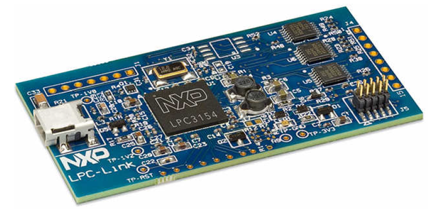
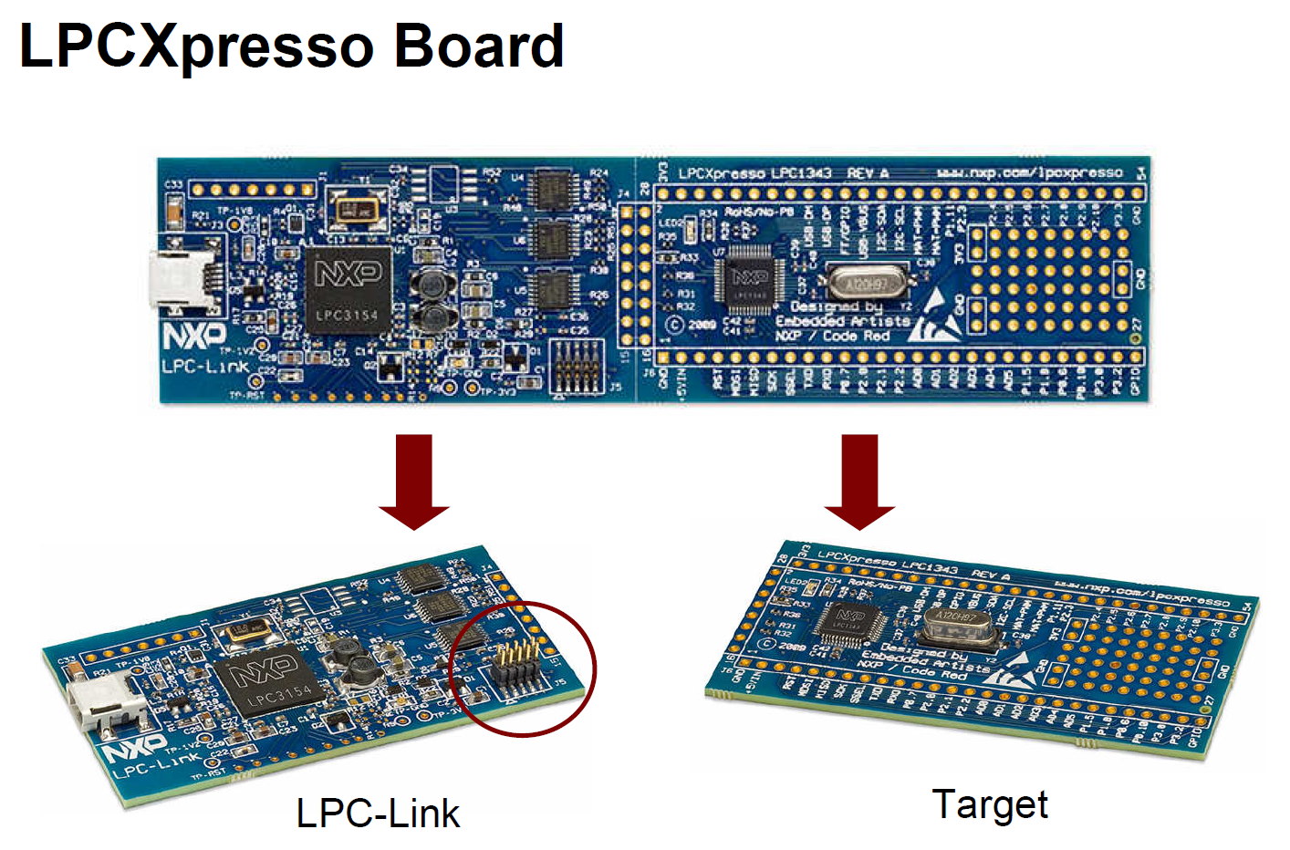
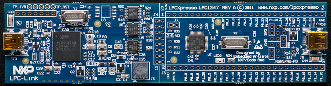
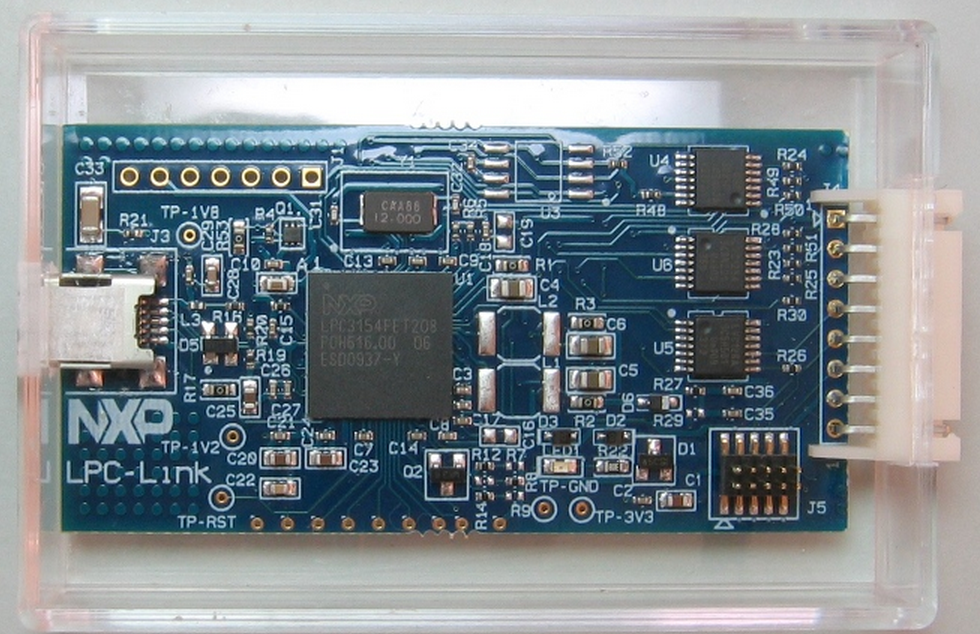
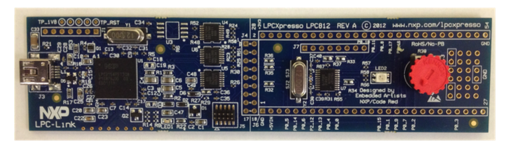
NXP LPC-Link LPC3154
LPC-Link:
LPC-Link调试探针由恩智浦、Code Red和Embedded Artists三方共同开发,
该探针可与目标板断开,利用板载10针JTAG/SWD连接器直接用于客户自己的设计。
LPC-Link采用LPC3154 作为基于ARM9的调试引擎,提供高速USB接口,支持快速编码下载和调试。
LPC-Link
LPC-Link is an integrated JTAG/SWD debug interface based on
LPC3154 (ARM9)
LPC-Link can be used as a standalone JTAG debugger with other LPC
target boards. So, no need for a separate debug probe!
LPC-Link makes it possible for users to experience the same user
interface all the way to final code development and testing


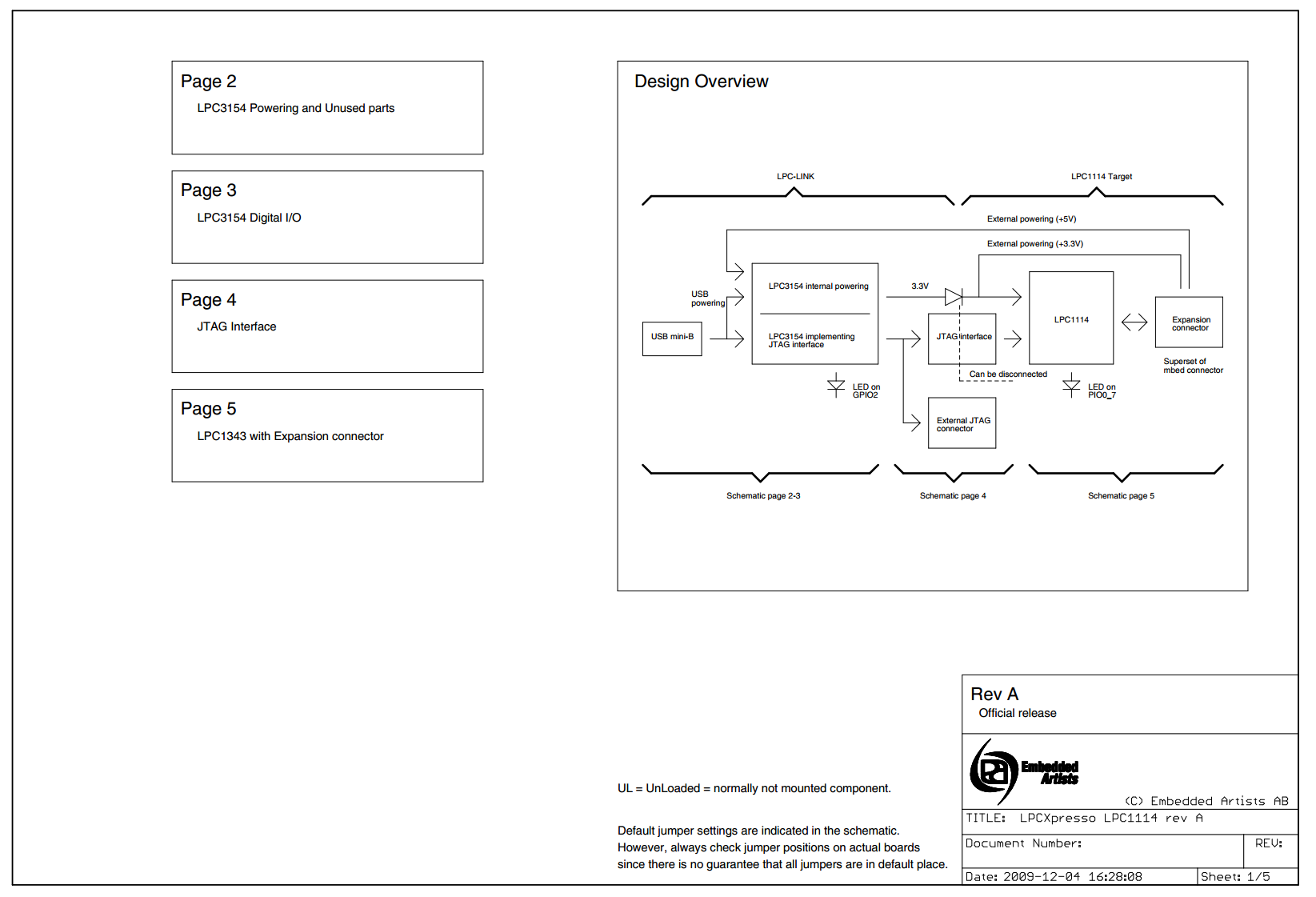
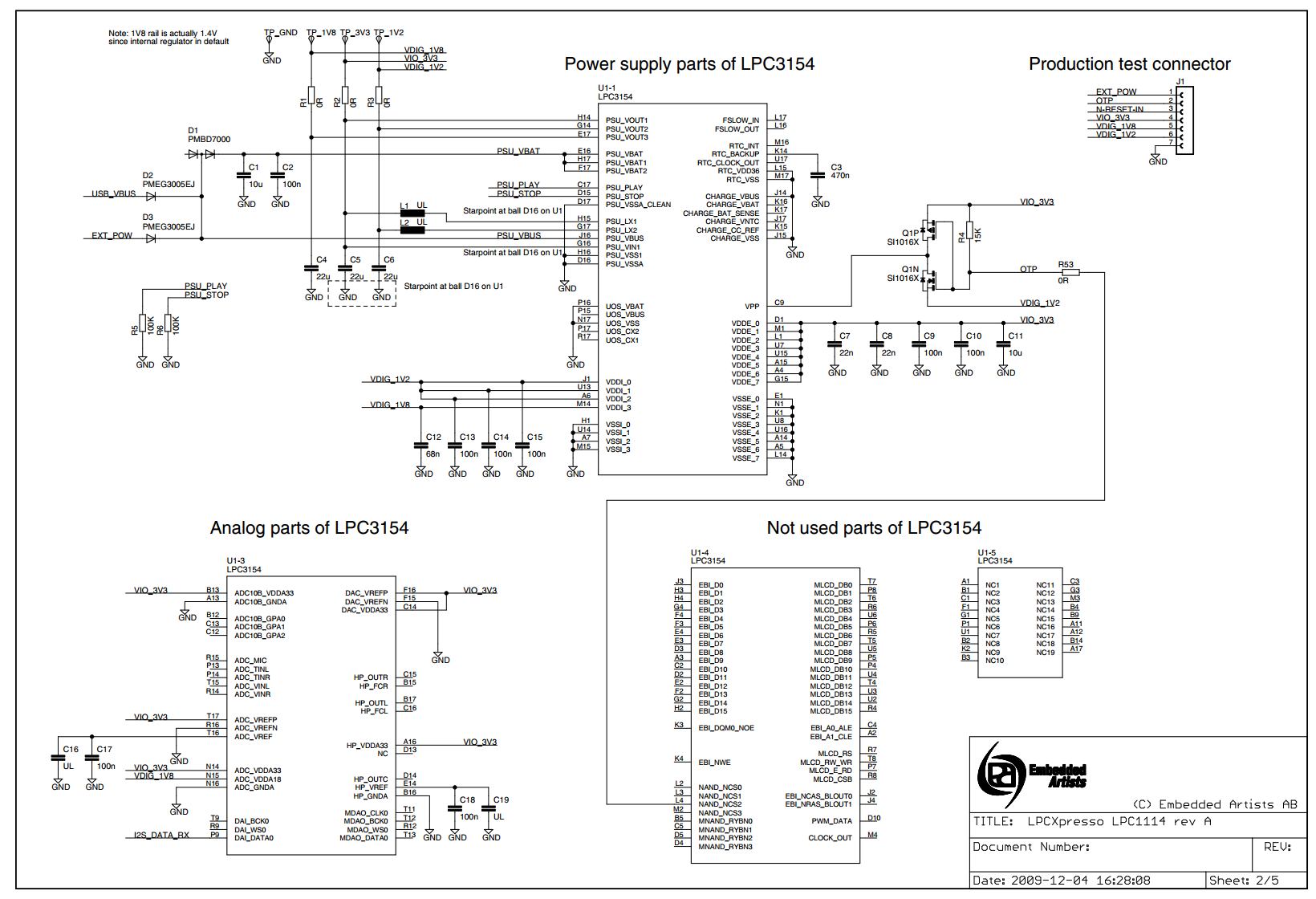
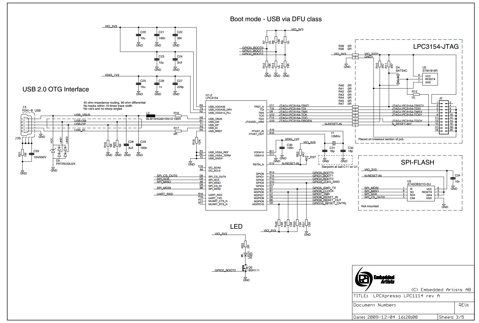
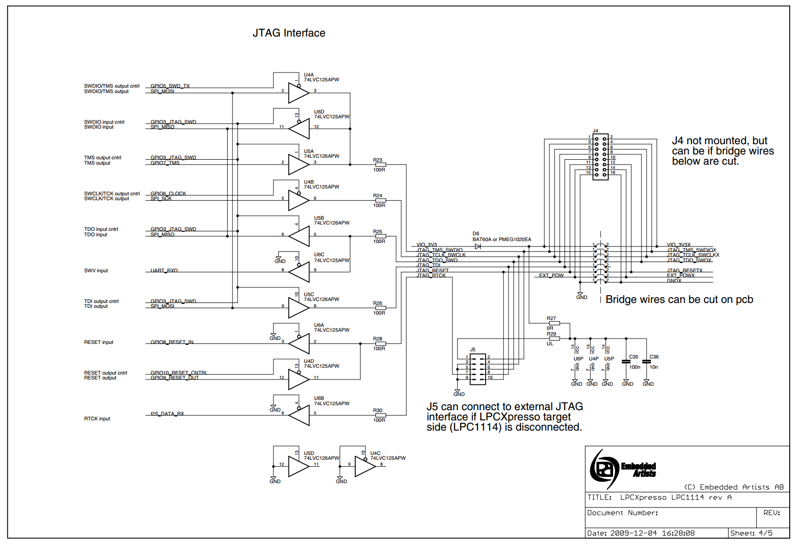
http://www.embeddedartists.com/sites/default/files/docs/schematics/LPCXpressoLPC1114revA.pdf
Booting LPC-Link
Normally, LPC-Link is booted automatically when starting a debug session via the LPCXpresso IDE.
However, under certain circumstances - such as when using the command line flash utility, you may need to boot it manually.
Background
When powered on, LPC-Link hardware makes use of the DFU mechanism (Device Firmware Update) to allow the host to download driver code into on-board RAM.
This scheme offers great flexibility and ensures that the latest compatible firmware will be used for a given version of LPCXpresso IDE.
Before boot, LPC-Link appears as a USB device with details:
After boot, LPC-Link will appear as a USB device with details:
Note: LPC-Link may be booted as a winusb device having a ProductID of 0x9 (as above) or a HID device having a ProductID of 0x7.
Note: the standard utilities to explore USB devices on our supported host platforms are:
- Windows - Device ManagerLinux - terminal command: lsusb
- LPCXpressoIDE also provides a listusb utility in:
- <install_dir>\lpcxpresso\bin\Scripts
- LPCXpressoIDE also provides a listusb utility in:
- Mac OSX - terminal command: system_profiler SPUSBDataType
The procedure to manually boot the probes for our supported host operating systems shown below.
Using the Command Line
From LPCXpresso IDE version 7.3x and later, a boot script is supplied for all supported platforms. To make use of this script:
- cd <install_dir>\lpcxpresso\bin and run
- boot_link1
For versions of LPCXpresso IDE prior to 7.3
Windows
On Windows, we provide a script to perform this operation.
-
cd <install_dir>\lpcxpresso\bin\Scripts, and run
-
bootLPCXpresso.cmd type
- where
-
type = winusb for Windows 8.x / XP, or
-
type = hid for Windows Vista / 7
-
- where
Note: if you don't specify a type, the script will try to load to appropriate code for your host OS.
Linux/Mac OS X
Here we need to locate the dfu-util utility and pass the parameters for the device and code etc.
-
cd <install_dir>/lpcxpresso/bin, and run
-
dfu-util -d 0x471:0xdf55 -c 0 -t 2048 -R -D LPCXpressoWIN.enc
Troubleshooting
If you have been able to use LPC-Link in a debug session but now see issues such as "No compatible emulator available" or "Priority 0 connection to this core already taken" when trying to perform a debug operation ...
- ensure you have shut down any previous debug session
- You must close a debug session (press the Red 'terminate' button) before starting another debug session
- It is possible that the debug driver is still running in the background. Use the task manager or equivalent to kill any tasks called:
- crt_emu_*
- arm-none-eabi_gdb*
If your host has never worked with LPC-Link, first perform some basic checks with reference to the background information at the beginning of this FAQ.
- Try a different USB cable!
- Try a different USB port. If your host has USB3 and USB2, then try a USB2 portIf using a USB hub, first try a direct connection to the host computer
- there are know issues with motherboard USB3 firmware, ensure your host is using the latest driver from the manufacturer
- Note: this is not referencing the host OS driver but the motherboard firmware of the USB port
- there are know issues with motherboard USB3 firmware, ensure your host is using the latest driver from the manufacturer
- Try completely removing and re-installing the host device driver
- If using Windows 8.1, then sometimes the Windows USB power settings can cause problems. For more details use your favourite search engine to search for "windows 8 usb power settings" or similar. For example:
Reprogramming LPC3154 at LPCxpresso
I wonder, if that's possible to load lpc3154 at LPCExpresso board with custom firmware?
I see that chip supports secure boot, so if AES key was programmed, it is impossible without knowing the key? Or are there any options to boot lpc3154 without knowing the key? (SD, flash, USB, JTAG... Anything?)
Does anyone know if key was indeed loaded?
Just buying new lpc3154 is not an option - they are not in stock here anywhere, and wait times are 4 weeks+ (and a price tag > than a price of this board)...
From what i gather the AES key is loaded into the chip. And also there may be a CR232 check on the firmware as well or OTP fuses set
Supports un-secure boot from UART and USB (DFU class) interfaces during development. Once the AES key is programmed in the OTP, only secure boot is allowed through UART and USB.
This doesn't mean it cant be hacked, if you put the time into it. I would check to see if the JTAG pins have been disabled and start from there.
some interesting statements from the user guide
7.1 Production line use case At the NXP production line the OTP will be tested and programmed using JTAG.
In test mode, the fuse block itself will be accessed directly.
During programming the VPP will need a higher voltage than in the application use case.
Written data is checked afterwards by reading out the fuses (using a low voltage on VPP)
The customer will also program the OTP only at the production line,
here DFU programming will be used.
An image for programming customer-selected bits can be loaded into the device via USB.

7.2 Application use case nitially it is important to make sure that the data_15 register
is updated early during the initialization (by boot-code) this will set the security level.
Four levels of security are implemented in the design:

• Level 0: nothing is protected.

• Level 1: password protected. In this level, JTAG can be enabled by software after password sequence
(depends on customer application) by setting the sticky bit 'JTAG_EN' in OTP_con register.
• Level 2: In this level, JTAG access can be enabled using special test equipment. Used by NXP for Returned Material Analysis only.

• Level 3: JTAG is completely disabled and hence the chip is virtually locked.

The customer can program the security level of the chip.
For level 1, fuse-bit 509 should be set.
For level 2, fuse-bits 509 and 510 are set.
For level 3, fuse-bits 509, 510 and 511 are programmed.
A special case will be for the customer to disable writing to the fuses,
but since in application a low voltage (for reading) will be connected to the VPP,
writing will not be possible anyway. During normal application,
the fuses will already have been programmed on the production line.

So three options remain: copying the fuse data into the data registers, reading this data, and setting the read protection.
The boot code will copy the fuse data into the data registers because this is needed for security and DRM.
After this, the data can be read from the data registers via the APB0 bus (according to the read protection settings).
If the key is truly loaded, you will only be able to load custom firmware if you have the key.
The question was answered here on the LPCXpresso forum. The device can only load DFU software from Code Red.
From NXP_USA:
The LPC-LINK boards distributed embedded in LPCXpresso, can only load DFU firmware from our LPCXpresso IDE partner Code Red.
However, the LPCXpresso schematics are posted here:

http://www.embeddedartists.com/products/lpcxpresso/lpc1343_xpr.php?tab=res.

They are a useful reference for a more flexible LPC3154 design that could accept arbitrary firmware via DFU.
I have been experimenting with the LPCXpresso LPC1114 board. It appears the programming interface (LPC3154) is USB High-Speed (480 MHz) and it seems extremely particular about the USB cable you use. If the cable (or the host port) isn't top notch, it may be very unstable, crash a lot, and even lock up other USB devices on the same root port. From having written a number of USB stacks, my guess is this particular USB stack is not very robust in terms of error and exception handling.
The fact they used such a high-end ARM for a simple JTAG/SWD interface is laughable, that MCU was over $13 (at Digikey) last time I looked.
I would recommend using a different SWD interface and disconnecting the one on the board if you have any difficulty. This should also permit the use other (non Code Red) IDEs with these boards.
(If you encounter USB problems with any device (even Full-Speed 12 MHz) and you are using the USB host connectors in the front of a PC system unit, try using the rear connectors on the MB itself. I have seen well-known brands of PCs with non-compliant (and very flaky) cabling to the front of the system unit.)
Izzy Weird

