


STM32的PWM输入模式设置并用DMA接收数据
参考 :STM32输入捕获模式设置并用DMA接收数据
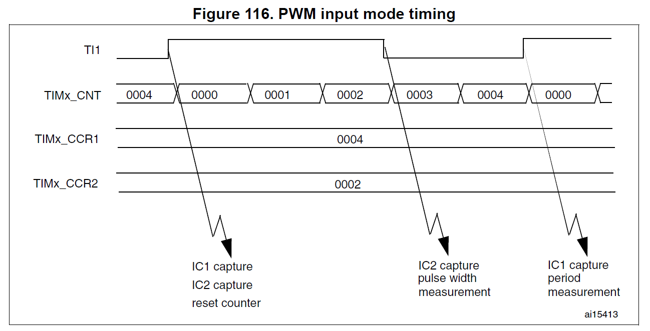
PWM input mode
This mode is a particular case of input capture mode.
The procedure is the same except:
Two ICx signals are mapped on the same TIx input.
These 2 ICx signals are active on edges with opposite polarity.
One of the two TIxFP signals is selected as trigger input and the slave mode controller is configured in reset mode.
For example, you can measure the period (in TIMx_CCR1 register) and the duty cycle (in TIMx_CCR2 register)
of the PWM applied on TI1 using the following procedure (depending on CK_INT frequency and prescaler value):
Select the active input for TIMx_CCR1: write the CC1S bits to 01 in the TIMx_CCMR1 register (TI1 selected).
Select the active polarity for TI1FP1 (used both for capture in TIMx_CCR1 and counter clear): write the CC1P and CC1NP bits to ‘0’ (active on rising edge).
Select the active input for TIMx_CCR2: write the CC2S bits to 10 in the TIMx_CCMR1 register (TI1 selected).
Select the active polarity for TI1FP2 (used for capture in TIMx_CCR2): write the CC2P and CC2NP bits to ‘1’ (active on falling edge).
Select the valid trigger input: write the TS bits to 101 in the TIMx_SMCR register (TI1FP1 selected).
Configure the slave mode controller in reset mode: write the SMS bits to 100 in the TIMx_SMCR register.
Enable the captures: write the CC1E and CC2E bits to ‘1’ in the TIMx_CCER register.
STM32的PWM输入模式设置并用DMA接收数据
项目中需要进行红外学习,如果采用输入捕获的方式,因为定时器只能捕获上升沿或者下降沿,
所以只能获得周期,而不能得到具体的红外波的高低电平的时间.
所以采用PWM输入的方式进行捕获. 采用的是PA8脚,对应TIM1的通道1.
/*********************************************************************
 *             函数
 **********************************************************************/

/*********************************************************************
 *             接口函数:初始化红外学习模块
 **********************************************************************/

void inf_infrared_study_init( void )
{
  //初始化io口
  inf_init_io( );
  //初始化中断
  //inf_init_irq();
  //初始化定时器
  inf_init_timer( );

  //打开DMA
  inf_infrared_study_open_dma( 1 );
  //打开定时器
  inf_infrared_study_open_timer( 1 );
}

/*********************************************************************
 *             初始化io口
 **********************************************************************/

static void inf_init_io( void )
{
  //定义IO初始化结构体
  GPIO_InitTypeDef GPIO_InitStructure;

  //初始化时钟
  RCC_APB2PeriphClockCmd( RCC_APB2Periph_GPIOB, ENABLE );
  //管脚初始化
  GPIO_InitStructure.GPIO_Pin = GPIO_Pin_8;
  //设置为输入
  GPIO_InitStructure.GPIO_Mode = GPIO_Mode_IN_FLOATING;
  //初始化
  GPIO_Init( GPIOA, &GPIO_InitStructure );
}

/*********************************************************************
 *             初始化中断
 **********************************************************************/

static void inf_init_irq( void )
{
  //定义外部中断结构体
  EXTI_InitTypeDef EXTI_InitStructure;

  //初始化中断脚复用时钟
  RCC_APB2PeriphClockCmd( RCC_APB2Periph_AFIO, ENABLE );
  //配置中断源
  GPIO_EXTILineConfig( GPIO_PortSourceGPIOB, GPIO_PinSource1 );
  // 配置下降沿触发
  EXTI_ClearITPendingBit( EXTI_Line1 );
  EXTI_InitStructure.EXTI_Line = EXTI_Line1;
  EXTI_InitStructure.EXTI_Trigger = EXTI_Trigger_Falling;
  EXTI_InitStructure.EXTI_Mode = EXTI_Mode_Interrupt;
  EXTI_InitStructure.EXTI_LineCmd = ENABLE;
  EXTI_Init( &EXTI_InitStructure );
}

/*********************************************************************
 *             初始化定时器
 **********************************************************************/

static void inf_init_timer( void )
{
  //定义定时器结构体
  TIM_TimeBaseInitTypeDef timInitStruct;
  //输入捕获结构体
  TIM_ICInitTypeDef tim_icinit;
  //定义DMA结构体
  DMA_InitTypeDef DMA_InitStructure;

  //启动DMA时钟
  RCC_AHBPeriphClockCmd( RCC_AHBPeriph_DMA1, ENABLE );
  //DMA1通道配置
  DMA_DeInit( DMA1_Channel2 );
  //外设地址
  DMA_InitStructure.DMA_PeripheralBaseAddr = (uint32_t) ( &TIM1->CCR1 );
  //内存地址
  DMA_InitStructure.DMA_MemoryBaseAddr = (uint32_t) Rx_Buf_Tim_Dma1;
  //dma传输方向单向
  DMA_InitStructure.DMA_DIR = DMA_DIR_PeripheralSRC;
  //设置DMA在传输时缓冲区的长度
  DMA_InitStructure.DMA_BufferSize = RX_LEN_TIM_DMA;
  //设置DMA的外设递增模式,一个外设
  DMA_InitStructure.DMA_PeripheralInc = DMA_PeripheralInc_Disable;
  //设置DMA的内存递增模式
  DMA_InitStructure.DMA_MemoryInc = DMA_MemoryInc_Enable;
  //外设数据字长
  DMA_InitStructure.DMA_PeripheralDataSize = DMA_PeripheralDataSize_HalfWord;
  //内存数据字长
  DMA_InitStructure.DMA_MemoryDataSize = DMA_MemoryDataSize_HalfWord;
  //设置DMA的传输模式
  //DMA_InitStructure.DMA_Mode = DMA_Mode_Normal;
  DMA_InitStructure.DMA_Mode = DMA_Mode_Circular;
  //设置DMA的优先级别
  DMA_InitStructure.DMA_Priority = DMA_Priority_High;
  //设置DMA的2个memory中的变量互相访问
  DMA_InitStructure.DMA_M2M = DMA_M2M_Disable;
  DMA_Init( DMA1_Channel2, &DMA_InitStructure );

  //启动DMA时钟
  RCC_AHBPeriphClockCmd( RCC_AHBPeriph_DMA1, ENABLE );
  //DMA1通道配置
  DMA_DeInit( DMA1_Channel3 );
  //外设地址
  DMA_InitStructure.DMA_PeripheralBaseAddr = (uint32_t) ( &TIM1->CCR2 );
  //内存地址
  DMA_InitStructure.DMA_MemoryBaseAddr = (uint32_t) Rx_Buf_Tim_Dma2;
  //dma传输方向单向
  DMA_InitStructure.DMA_DIR = DMA_DIR_PeripheralSRC;
  //设置DMA在传输时缓冲区的长度
  DMA_InitStructure.DMA_BufferSize = RX_LEN_TIM_DMA;
  //设置DMA的外设递增模式,一个外设
  DMA_InitStructure.DMA_PeripheralInc = DMA_PeripheralInc_Disable;
  //设置DMA的内存递增模式
  DMA_InitStructure.DMA_MemoryInc = DMA_MemoryInc_Enable;
  //外设数据字长
  DMA_InitStructure.DMA_PeripheralDataSize = DMA_PeripheralDataSize_HalfWord;
  //内存数据字长
  DMA_InitStructure.DMA_MemoryDataSize = DMA_MemoryDataSize_HalfWord;
  //设置DMA的传输模式
  //DMA_InitStructure.DMA_Mode = DMA_Mode_Normal;
  DMA_InitStructure.DMA_Mode = DMA_Mode_Circular;
  //设置DMA的优先级别
  DMA_InitStructure.DMA_Priority = DMA_Priority_High;
  //设置DMA的2个memory中的变量互相访问
  DMA_InitStructure.DMA_M2M = DMA_M2M_Disable;
  DMA_Init( DMA1_Channel3, &DMA_InitStructure );

  //开启时钟
  RCC_APB2PeriphClockCmd( RCC_APB2Periph_TIM1, ENABLE );
  //重新将Timer设置为缺省值
  TIM_DeInit( TIM1 );
  //采用内部时钟提供时钟源
  TIM_InternalClockConfig( TIM1 );
  //预分频
  timInitStruct.TIM_ClockDivision = TIM_CKD_DIV1;
  //计数频率为500ns跳转1次
  timInitStruct.TIM_Prescaler = SystemCoreClock / 1000000 - 1;
  //向上计数
  timInitStruct.TIM_CounterMode = TIM_CounterMode_Up;
  timInitStruct.TIM_RepetitionCounter = 0;
  //这个值实际上就是TIMX->ARR,延时开始时重新设定即可
  timInitStruct.TIM_Period = 0xffff;
  //初始化定时器
  TIM_TimeBaseInit( TIM1, &timInitStruct );

  //输入捕获配置
  //选择通道
  tim_icinit.TIM_Channel = TIM_Channel_1;
  //硬件滤波
  tim_icinit.TIM_ICFilter = 0x0;
  //触发捕获的电平
  tim_icinit.TIM_ICPolarity = TIM_ICPolarity_Falling;
  //每次检测到触发电平都捕获
  tim_icinit.TIM_ICPrescaler = TIM_ICPSC_DIV1;
  //通道方向选择
  tim_icinit.TIM_ICSelection = TIM_ICSelection_DirectTI;
  //初始化
  //TIM_ICInit(TIM1,&tim_icinit);
  TIM_PWMIConfig( TIM1, &tim_icinit );
  //禁止ARR预装载缓冲器
  //TIM_ARRPreloadConfig(TIM1, DISABLE);

  //输入跳变选择
  TIM_SelectInputTrigger( TIM1, TIM_TS_TI1FP1 );
  //从机模式:复位模式
  TIM_SelectSlaveMode( TIM1, TIM_SlaveMode_Reset );
  //主从模式选择
  TIM_SelectMasterSlaveMode( TIM1, TIM_MasterSlaveMode_Enable );

  //配置定时器的DMA
  TIM_DMAConfig( TIM1, TIM_DMABase_CCR1, TIM_DMABurstLength_2Bytes );
  //产生DMA请求信号
  TIM_DMACmd( TIM1, TIM_DMA_CC1, ENABLE );

  //配置定时器的DMA
  TIM_DMAConfig( TIM1, TIM_DMABase_CCR2, TIM_DMABurstLength_2Bytes );
  //产生DMA请求信号
  TIM_DMACmd( TIM1, TIM_DMA_CC2, ENABLE );

  //打开定时器
  TIM_Cmd( TIM1, ENABLE );
}

/*********************************************************************
 *             接口函数:打开定时器
 *参数:state:状态:0:关闭,1:打开
 **********************************************************************/

void inf_infrared_study_open_timer( uint8_t state )
{
  if ( state )
  {
    TIM_Cmd( TIM1, ENABLE );
  }
  else
  {
    TIM_Cmd( TIM1, DISABLE );
  }
}

/*********************************************************************
 *             接口函数:打开中断
 *参数:state:状态:0:关闭,1:打开
 **********************************************************************/

void inf_infrared_study_open_irq( uint8_t state )
{
  //定义中断结构体
  NVIC_InitTypeDef NVIC_InitStructure;

  if ( state )
  {
    //打开中断
    NVIC_InitStructure.NVIC_IRQChannel = EXTI1_IRQn;        //通道设置为外部中断线
    NVIC_InitStructure.NVIC_IRQChannelPreemptionPriority = 1;     //中断抢占先等级
    NVIC_InitStructure.NVIC_IRQChannelSubPriority = 0;            //中断响应优先级
    NVIC_InitStructure.NVIC_IRQChannelCmd = ENABLE;               //打开中断
    NVIC_Init( &NVIC_InitStructure );                                 //初始化
  }
  else
  {
    //关闭中断
    NVIC_InitStructure.NVIC_IRQChannel = EXTI1_IRQn;        //通道设置为外部中断线
    NVIC_InitStructure.NVIC_IRQChannelPreemptionPriority = 1;     //中断抢占先等级
    NVIC_InitStructure.NVIC_IRQChannelSubPriority = 0;            //中断响应优先级
    NVIC_InitStructure.NVIC_IRQChannelCmd = DISABLE;              //打开中断
    NVIC_Init( &NVIC_InitStructure );                                 //初始化
  }
}

/*********************************************************************
 *             接口函数:打开DMA
 *参数:state:状态:0:关闭,1:打开
 **********************************************************************/

void inf_infrared_study_open_dma( uint8_t state )
{
  if ( state )
  {
    //设置传输数据长度
    //DMA_SetCurrDataCounter(DMA1_Channel3,RX_LEN_TIM_DMA);
    //打开DMA
    DMA_Cmd( DMA1_Channel2, ENABLE );
    DMA_Cmd( DMA1_Channel3, ENABLE );
  }
  else
  {
    DMA_Cmd( DMA1_Channel2, DISABLE );
    DMA_Cmd( DMA1_Channel3, ENABLE );
  }
}

/*********************************************************************
 *             接口函数:得到DMA接收帧长
 *返回:帧长
 **********************************************************************/

uint16_t inf_infrared_study_dma_rx_len( void )
{
  //获得接收帧帧长
  return ( RX_LEN_TIM_DMA - DMA_GetCurrDataCounter( DMA1_Channel2 ) );
}


 浙公网安备 33010602011771号