Boost Converter
Single Inductor Buck-Boost Converter in Tiny WCSP
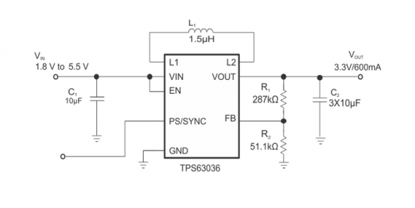
The TPS63036 is a non inverting buck-boost converter able to provide a regulated output voltage from an input supply that can be higher or lower than the output voltage. The buck-boost converter is based on a fixed frequency, pulse-width-modulation (PWM) controller using synchronous rectification to obtain maximum efficiency. At low load currents, the converter enters Power Save mode to maintain high efficiency over a wide load current range. The Power Save mode can be disabled, forcing the converter to operate at a fixed switching frequency. The maximum average current in the switches is limited to a typical value of 1000 mA. The output voltage is programmable using an external resistor divider. The converter can be disabled to minimize battery drain. During shutdown, the load is disconnected from the battery. The device is packaged 8-pin WCSP package measuring 1.854 mm x 1.076 mm (YFG).
Features
- Input Voltage Range: 1.8V to 5.5V
- Real Buck or Boost operation
- Adjustable and fixed output voltage version
- Up to 96% Efficiency
- Device Quiescent Current less than 50µA
- Fixed and Adjustable Output Voltage Options
- Power Save Mode for Improved Efficiency at Low Output Power
- Forced Fixed Frequency Operation and Synchronization Possible
- Load Disconnect During Shutdown
- Over-Temperature Protection
- Available in Small 1.854 mm x 1.076 mm, WCSP-8 Package
12v to 300v Boost Converter - Ideal Inductor for 9kOhm load
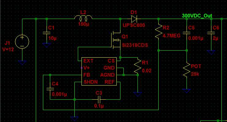
MAX1771
The inductor currently being used is a SRN1060-151M, unfourtanately it has a peak current of 1.25A and a saturation current of 1.8A. My guess is that the low saturation and peak current are causing problems with lower loads. I'm rather inexperienced with actually ordering proper parts and mostly ended up getting parts that fit the initial specs (matched values and picked low DC-resistance).
I take it that for a 9kOhm load I would need an inductor that can handle up to 3A. The NMOS is a STD8NM50N which can handle up to 5A and the DIODE is an EGL34G-E3/98GICT-ND.
Can anyone recommend an affordable inductor on DigiKey that can get the job done? Or changes to the circuit that may assist in making the 300V with 9kOhm load possible?
If you know the inductance (150uH) and you know the maximum on time (12us) and you know the minimum switch off time (2.8us) you can take a stab at calculating how much power you can transfer.
In 20usec, how much energy can you put into the inductor? In 20us + 2.8us you can assume that energy may be transferred pretty much totally (near, better than 90% I'd say). The cycle repeats every 22.8us i.e. 43,860 times a second.
What are the joules per second - this can be calculated now.
OK in 20us the inductor current will rise to V dt/L because V= L di/dt. Plug the numbers in and I get I to be 12V x 20us / 150uH = 1.6A.
What is the energy? It's 0.5 x L x I^2 = 192uJ. But this happens 43,860 times a second therefore the power is 8.42W.
Your circuit cannot deliver a power greater than 8.42W and if I took losses and only 90% energy transfer it looks more like 7.5W.
You want 300V across 9kohm and that is an output power of 10W - you don't just want an inductor that doesn't saturate you want a lower value inductor. Why? A lower value inductor will attain a higher current and it's current squared that gives you the energy to push to the output.
100uH - current peaks at 2.4A and energy in one cycle is 288uJ. Power is therefore up to 12.6W.
This would be my recommendation - try 100uH and if it's still a little bit light on power (due to inefficiences) try a better FET with less-than the present 0.7ohm on resistance. Bear in mind it's really tricky to estimate how much energy stored in the inductor can be thrown across to the output so the inductor may indeed have to be lower that 100uH and I feel you are starting push the chip to its limitations and you may need to reconsider a chip upgrade.
500kHz、36V输出、600mW PWM升压型DC-DC转换器
小尺寸、2.7V至11V boost转换器,输出功率大于600mW,采用TDFN封装
MAX15032固定频率脉宽调制(PWM)、低噪声升压型DC-DC转换器用于需要局部产生高压的低压系统。器件能够从2.9V输入产生低噪声、高压输出,输出功率可达600mW。MAX15032能够适合各种应用,如PIN或变容二极管偏置以及LCD显示器。MAX15032采用+2.7V至+11V单电源供电。
固定频率(500kHz)、电流模式PWM架构提供低噪声输出,易于滤波。内置高压横向DMOS功率开关允许器件提供高达36V的输出电压,MAX15032具有关断省电模式。
MAX15032提供小尺寸、增强散热的3mm x 3mm、8引脚TDFN封装,工作于-40°C至+125°C汽车级温度范围。
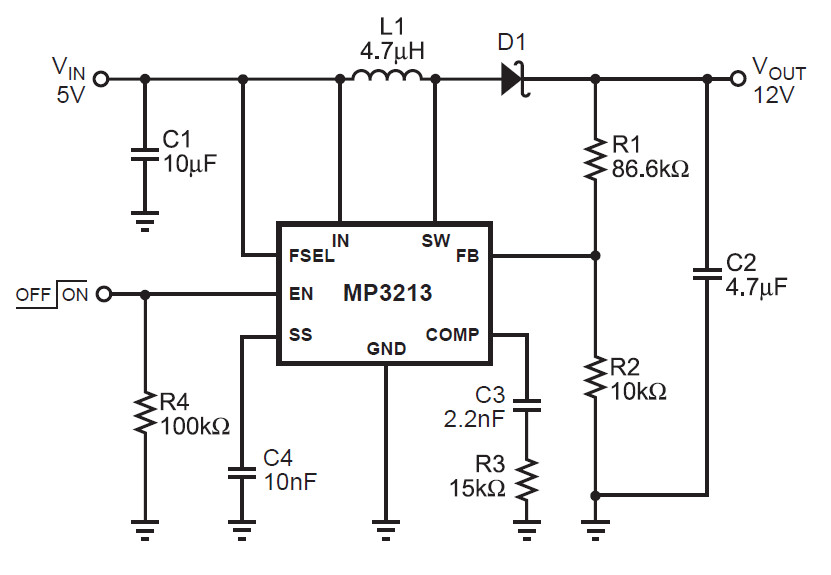
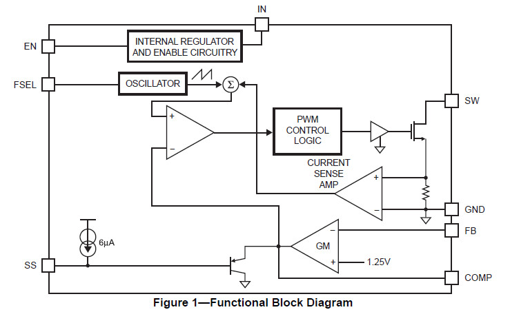
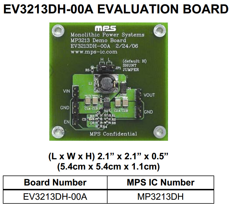
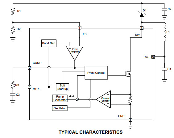
MP3213DH是一个700kHz/1.3MHz ,3.5A的升压DC-DC,其采用MSOP-8的引脚封装,
he MP3213 is a current mode step up converter with a 3.5A, 0.18Ω internal switch to provide a highly efficient regulator with fast response. The MP3213 operates at 700kHz or 1.3MHz allowing for easy filtering and low noise. An external compensation pin gives the user flexibility in setting loop dynamics, which allows the use of small, low ESR ceramic output capacitors. Soft-start results in small inrush current and can be programmed with an external capacitor. The MP3213 operates from an input voltage as low as 2.5V and can generate 12V at up to 500mA from a 5V supply. The MP3213 includes under-voltage lockout, current limiting and thermal overload protection to prevent damage in the event of an output overload. The MP3213 is available in a low profile 8-pin MSOP package with exposed pad.
3.5A, 0.18Ω, 25V Power MOSFET
• Uses Tiny Capacitors and Inductors
• Pin Selectable 700kHz or 1.3MHz Fixed Switching Frequency
• Programmable Soft-Start
• Operates with Input Voltage as Low as 2.5V and Output Voltage as High as 22V
• 12V at 500mA from 5V Input
• UVLO, Thermal Shutdown
• Internal Current Limit
• Available in an 8-Pin MSOP Package with Exposed Pad

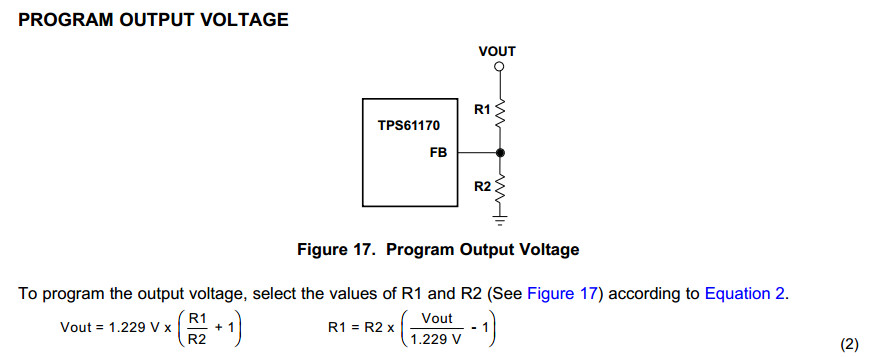
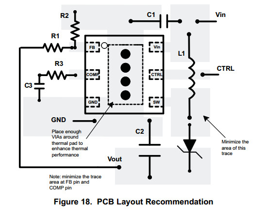
TPS61170
内置30V开关的LCD偏置电源
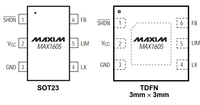
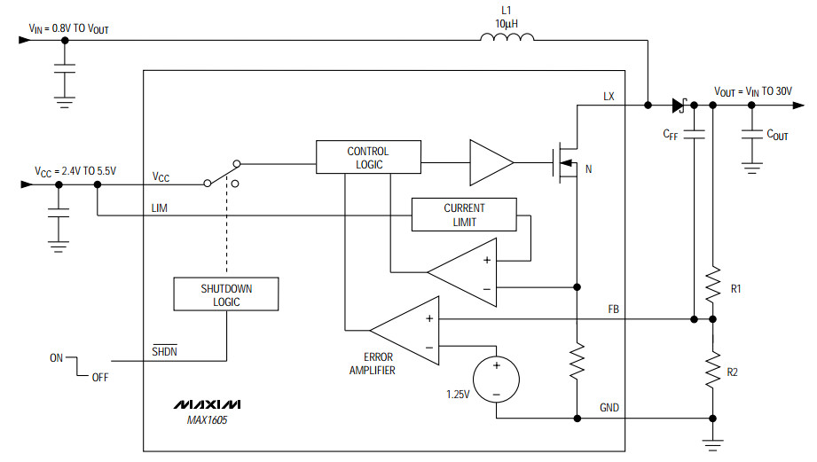
The MAX1605 boost converter contains a 0.5A internal switch in a tiny 6-pin SOT23 package. The IC operates from a +2.4V to +5.5V supply voltage, but can boost battery voltages as low as 0.8V up to 30V at the output.
The MAX1605 uses a unique control scheme providing the highest efficiency over a wide range of load conditions. An internal 0.5A MOSFET reduces external component count, and a high switching frequency (up to 500kHz) allows for tiny surface-mount components. The current limit can be set to 500mA, 250mA, or 125mA, allowing the user to reduce the output ripple and component size in low-current applications.
Additional features include a low quiescent supply current and a shutdown mode to save power. The MAX1605 is ideal for small LCD panels with low current requirements, but can also be used in other applications. A MAX1605EVKIT evaluation kit (EV kit) is available to help speed up design time.
- Adjustable Output Voltage up to 30V
- 20mA at 20V from a Single Li+ Battery
- 88% Efficiency
- Up to 500kHz Switching Frequency
- Selectable Inductor Current Limit (125mA, 250mA, or 500mA)
- 18µA Operating Supply Current
- 0.1µA Shutdown Current
- Avaiable in Two Small Packages
- 6-Pin TDFN
- 6-Pin SOT23
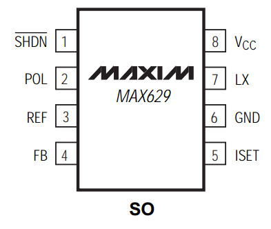
MAX629
28V、低功耗、高压、boost或反相DC-DC转换器
The MAX629 low-power DC-DC converter features an internal N-channel MOSFET switch and programmable current limiting. It is designed to supply positive or negative bias voltages up to ±28V from input voltages in the 0.8V to VOUT range, and can be configured for boost, flyback, and SEPIC topologies.
The MAX629's current-limited pulse-frequency-modulation (PFM) control scheme provides high efficiency over a wide range of load conditions. An internal, 0.5A N-channel MOSFET switch reduces the total part count, and a high switching frequency (up to 300kHz) allows for tiny surface-mount magnetics.
The MAX629's combination of low supply current, logic-controlled shutdown, small package, and tiny external components makes it an extremely compact and efficient high-voltage biasing solution that's ideal for battery-powered applications. The MAX629 is available in an 8-pin SO package.
- Internal, 500mA, 28V N-Channel Switch (No External FET Required)
- Generates Positive or Negative Output Voltages
- 80µA Supply Current
- 1µA Max Shutdown Current
- Up to 300kHz Switching Frequency
- Adjustable Current Limit Allows Use of Small, Inexpensive Inductors
- 8-Pin SO Package

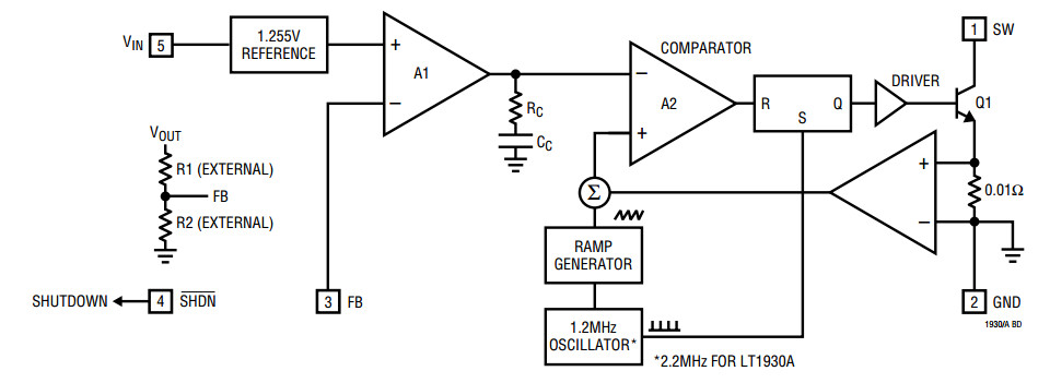
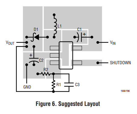
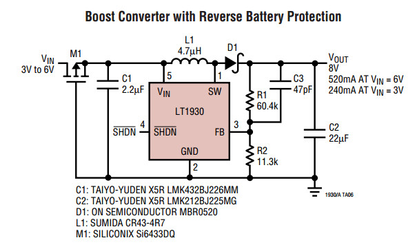
LT1930 - 采用 ThinSOT 封装的 1A,1.2MHz/2.2MHz 升压型 DC/DC 转换器
- 1.2MHz 开关频率 (LT1930)
- 2.2MHz 开关频率 (LT1930A)
- 低 VCESAT 开关:在 1A 电流时为 400mV
- 高输出电压:高达 34V
- 从 3.3V 输入可得到 5V/480mA (LT1930)
- 从 5V 输入可得到 12V/250mA (LT1930A)
- 宽输入范围:2.6V 至 16V
- 采用小型表面安装组件
- 低停机电流:< 1µA
- 扁平外型 (1mm) ThinSOT™ 封装
- 与 LT1613 引脚兼容

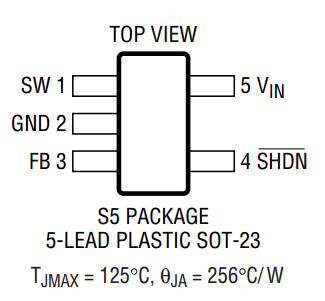
SW (Pin 1): Switch Pin. Connect inductor/diode here. Minimize trace area at this pin to reduce EMI.
GND (Pin 2): Ground. Tie directly to local ground plane.
FB (Pin 3): Feedback Pin. Reference voltage is 1.255V. Connect resistive divider tap here.
Minimize trace area at FB. Set VOUT according to VOUT = 1.255V(1 + R1/R2).
SHDN (Pin 4): Shutdown Pin. Tie to 2.4V or more to enable device. Ground to shut down.
VIN (Pin 5): Input Supply Pin. Must be locally bypassed.
5V to 13.5V dc dc boost converter
http://www.module.ro/boost%20converter.html
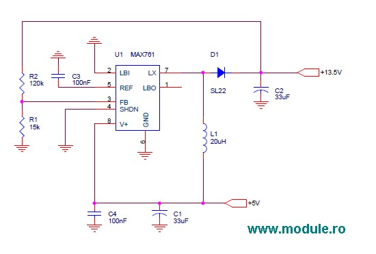
The Max761 is a 300kHz fixed frequency boost regulator that integrates a N-channel power MOSFET which allows peak currents up to 1A. In the standard application circuit the IC is powered from the output voltage ( bootstrapped mode ) and provide a fixed output of 12V (FB pin is connected to ground). For a 13.5V output voltage, the IC is powered from the supply voltage ( non- bootstrapped mode ), external resistor divider must be used as you can see in the follow circuit diagram:
With an input voltage of 4.5V to 5V, this circuit it produces a 13.5V output voltage at a load current of 150mA. The proprietary current-limited PFM control scheme provide a high efficiency, typically over 80%. The output voltage can be calculated using this formula:
Vout=1.5V x ( 1+R2/R1 )
BOM list:
- U1 Max761
- L1 20..47uH/min. 1.1A Isat inductor
- D1 SS14 / SL22 / MBRS130LT3 SMD Schottky diode
- C1 33uF/10V tantalum capacitor
- C2 33uF/min. 16V tantalum capacitor
- C3,C4 100nF/25V ceramic capacitors
- R1 15kΩ smd 1206 resistor
- R2 120kΩ smd 1206 resistor