
gray码计数器
Gray码在每次码跳变时,只有一位改变。
#(parameter N=5)
(
input clk,
input rst_n,
output reg [N-1:0] gray_cnt_out
);
reg [N-1:0] cnt;
reg [N-1:0] temp;
integer i;
always @ (posedge clk ,negedge rst_n)
begin
if(!rst_n)
cnt <= 5'd0;
else
cnt <= cnt +1'b1;
end
always @(cnt)
begin
temp[N-1] = cnt[N-1];
for(i=1; i<=N-1;i=i+1)
temp[i-1] = cnt[i-1]^cnt[i];
end
always @ (posedge clk ,negedge rst_n)
begin
if(!rst_n)
gray_cnt_out<=1'b0;
else
gray_cnt_out<=temp;
end
endmodule

在实际工程中,Gray码计数器广泛应用于跨时钟域设计,他用于将计数器的计数值从A时钟域传递给B时钟域。由于信号的传播延时,而且CLKA和CLKB没有固定的相位关系,CLKA_cnt的输出不能同时到达CLKB,如果用二进制计数器,则可能出现毛刺,从而导致设计错误;而如果采样Gray码计数器,根据Gray的特性,则可以有效地避免这个问题。

上面的格雷码编码方式可综合性和执行性不好,参照
Reference:
1.Vijay A. Nebhrajani," Asynchronous FIFO Architectures" part2
2. Clifford E. Cummings, Sunburst Design, Inc " Simulation and Synthesis Techniques for Asynchronous
FIFO Design"
给出的gray编写如下:
Gray code counters (having one bit change per counter transition) are often used in FIFO design and digital communication.
Here I will show two styles gray code counter.
Style #1
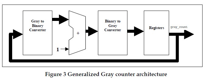
First style gray code counter uses a single set of flip-flops as the Gray code register with accompanying Gray-tobinary conversion, binary increment, and binary-to-Gray conversion.
module gray_counter
(
    input iclk,
    input irst_n,
    input ivalid,
    output reg [3:0] gray
);

wire [3:0] bin_counter;
wire [3:0] gray_counter;

reg  [3:0] G2B_counter;

// convert gray to  bin;
always@(*)
begin
    G2B_counter[3] = gray[3];
    G2B_counter[2] = gray[2] ^ G2B_counter[3];
    G2B_counter[1] = gray[1] ^ G2B_counter[2];
    G2B_counter[0] = gray[0] ^ G2B_counter[1];
end

//binary counter increased by one
assign bin_counter = bin_counter +ivalid;

//convert bin to gray
assign gray_counter = (bin_counter >>1) ^ bin_counter;

always@(posedge iclk or negedge irst_n)
begin
    if(!irst_n)
    begin
        gray <= 4'b0;
    end
    else
    begin
        gray <= gray_counter;
    end
end

endmodule
Style #2
A second Gray code counter style, the one described below, uses two sets of registers, one a binary counter and a second to capture a binary-to-Gray converted value. The intent of this Gray code counter style #2 is to utilize the binary carry structure, simplify the Gray-to-binary conversion; reduce combinational logic, and increase the upper frequency limit of the Gray code counter.
module graycounter
(
    input iclk,
    input irst_n,
    input ivalid,
    output     [ADDSIZE-1 : 0]  bin,
    output reg [ADDSIZE : 0]  gray
);

parameter ADDSIZE = 4;

wire[ADDSIZE : 0] binnext;
wire[ADDSIZE : 0] graynext;
reg[ADDSIZE : 0] bin_o;

assign binnext = bin_o + ivalid;

assign graynext = (binnext >>1) ^ binnext;

assign bin = bin_o[ADDSIZE-1 : 0];

always@(posedge iclk or negedge irst_n )
if(!irst_n)
    {bin_o, gray} <= 0;
else
    {bin_o, gray} <= {binnext, graynext};

endmodule
