设计一个BCD码计数器。
BCD码计数器的定义:
对于机器语言,机器与人不同,为了让人更好的了解机器语言的数据输出,选用4位二进制数据表示十进制里的每位数据,这便是BCD码。
以下便是BCD码与十进制对应的码表
0-----------0000----------0x0
1-----------0001----------0x1
2-----------0010----------0x2
3-----------0011----------0x3
4-----------0100----------0x4
5-----------0101----------0x5
6-----------0110----------0x6
7-----------0111----------0x7
8-----------1000----------0x8
9-----------1001----------0x9
这里举个例子,十进制数52,用BCD码表示即为0101 0010,通过这个例子,就可以很好的了解到BCD码的实际应用,即更好的区分十进制中的每一位数据。
下面说下这个计数器的设计,其实操作与计数器的基本没多大区别,重点运用到的就是上一篇讲到的计数器的级联原理,这篇文章的意义是为了为后面讲解数码管的显示做准备。
新建工程
程序设计:

module BCD_counter(clk,c_in,rst_n,c_out,q);
input clk;//计数器基准时钟
input c_in;//系统进位输入
input rst_n;//系统复位
output c_out ;//计数器进位输出
output [3:0]q;//计数器输出
reg [3:0]counter,c_out;
//执行计数过程
always@(posedge clk or negedge rst_n)
if(rst_n==0)
counter<=4'd0;
else if (counter==1'b1)
begin
if (counter==9)
counter<=4'd0;
else
counter<=counter+1'b1;
end
else
counter<=counter;
//产生进位信号
always@(posedge clk or negedge rst_n)
if(rst_n==0)
c_out<=1'b0;
else if (c_in==1'b1&&counter==4'd9)
c_out<=1'b1;
else
c_out<=1'b0;
assign q=counter;
endmodule
编写testbench
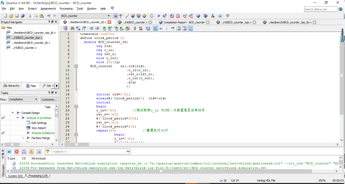
`timescale 1ns/1ns
`define clock_period 20
module BCD_counter_tb;
reg clk;
reg c_in;
reg rst_n;
wire c_out;
wire [3:0]q;
BCD_counter u0(.clk(clk),
.c_in(c_in),
.rst_n(rst_n),
.c_out(c_out),
.q(q)
);
initial clk=1'b1;
always#(`clock_period/2) clk=~clk;
initial
begin
c_in=1'b0; //测试即使c_in 为0时,计数器是否会有动作
rst_n=1'b0;
#(`clock_period*200);
rst_n=1'b1;
#(`clock_period*20);
repeat(30) //重复执行30次
begin
c_in=1'b1;
#`clock_period;
c_in=1'b0;
#(`clock_period*5);//保持5个时钟周期
end
#(`clock_period*20);
$stop;
end
endmodule
设置仿真路径进行仿真,可以看到每次计数满9次之后,产生一个c_out的输出信号。

下面对计数器进行级联。

module BCD_counter_top(clk,c_in,rst_n,c_out,q);
input clk;//计数器基准时钟
input c_in;//系统进位输入
input rst_n;//系统复位
output c_out ;//计数器进位输出
output [11:0]q;//计数器输出
wire c_out0,c_out1;
wire [3:0]q0,q1,q2;
BCD_counter u1(.clk(clk),
.c_in(c_in),
.rst_n(rst_n),
.c_out(c_out0),
.q(q0)
);
BCD_counter u2(.clk(clk),
.c_in(c_out0),
.rst_n(rst_n),
.c_out(c_out1),
.q(q1)
);
BCD_counter u3(.clk(clk),
.c_in(c_out1),
.rst_n(rst_n),
.c_out(c_out),
.q(q2)
);
assign q=({q2,q1,q0});//将三个信号拼接起来
endmodule
将其设置为顶层文件,编写testbench,并设置其路径。

`timescale 1ns/1ns
`define clock_period 20
module BCD_counter_top_tb;
reg clk;
reg c_in;
reg rst_n;
wire c_out;
wire [11:0]q;
BCD_counter_top BCD_counter_top0(
.clk(clk),
.c_in(c_in),
.rst_n(rst_n),
.c_out(c_out),
.q(q)
);
initial clk = 1'b1;
always#(`clock_period/2) clk = ~clk;
initial begin
rst_n = 1'b0;
c_in = 1'b0;
#(`clock_period*200);
rst_n = 1'b1;
#(`clock_period*20);
c_in = 1'b1;
#(`clock_period*5000);
$stop;
end
endmodule
点击仿真按钮进行前仿查看波形,可以看到进位到999后产生了进位输出,这说明整个设计是正确的。
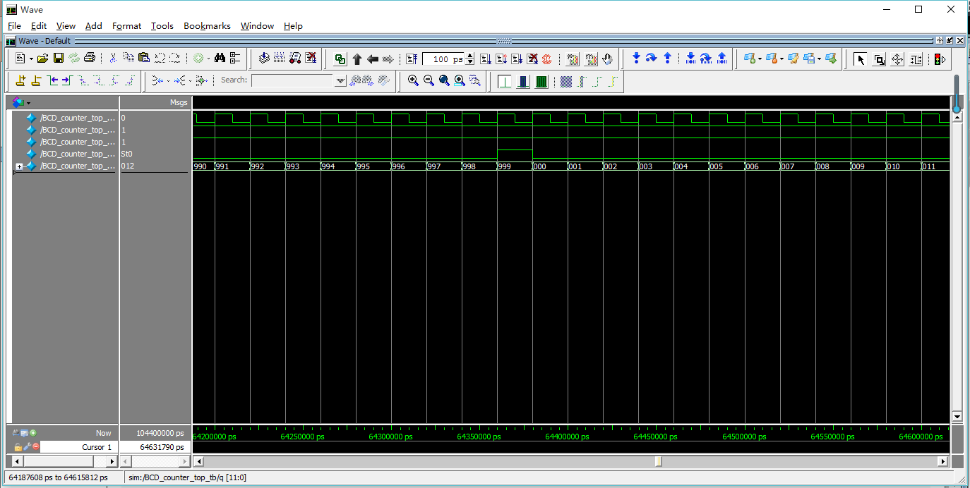
可以看到q的显示是按BCD码的码表显示的999,这说明zhegn


 浙公网安备 33010602011771号