《30天自制操作系统》读书笔记(5) GDT&IDT
- 梳理项目结构
项目做到现在, 前头的好多东西都忘了, 还是通过Makefile重新理解一下整个项目是如何编译的:
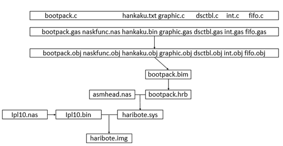
现在我们拥有这么9个文件:
- ipl10.nas InitialProgramLoader, 占用了软盘的第一个扇区并符合启动盘的规范, 默认被载入地址是0x7c00 到 0x7e00, 负责将10个柱面读入到0x8200到0x34fff (10个柱面共10*2*18 = 360 个扇区但是第一个没有被读入);
- asmhead.nas 包含一些暂时未知的设定;
- naskfun.nas 包含供C语言程序使用的汇编函数;
- bootpack.h 各种常量定义, 函数定义;
- hankaku.txt 字库文件;
- fifo.c 一个完整的循环队列的实现, 用于中断的缓冲;
- graphic.c 提供绘图函数, 绘制系统界面和指针, 打印字符;
- dsctbl.c GDT(全局符号描述符表) 和 IDT(中断描述符表) 的设定;
- int.c Interrupt Service Routines 的处理.
系统的内存分配:
- 0x7c00~0x7e00 ipl10.nas
- 0x26f800~0x26ffff IDT
- 0x270000~0x27ffff GDT
- 0x280000~0x2fffff bootpack.h
关于GDT IDT设定, 尽管书中已经尽量简化, 但是有相当多的细节需要注意, 并非一篇博文能容下的, 因此我决定不记录整个过程, 而是归纳其中需要注意的大的知识点, 毕竟这只是笔记…
- GDT
-
GDT
一个有用的链接: http://wiki.osdev.org/GDT_Tutorial
GDT (Global Descriptor Table) is a data structure in order to define the characteristics of the various memory areas used during program execution,
including the base address, the size and access privileges like executability and writability.
GDT 全称是全局段描述符表, 用来提供程序执行是需要的关于内存的各种信息, 表的条目成为GDT Entry, 大小为8字节, 包含了: 段的大小; 段的起始地址; 段的管理属性等信息.其结构如下:
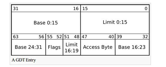
C语言表示如下:
struct SEGMENT_DESCRIPTOR
{
    short limit_low, base_low;
    char base_mid, access_right;
    char limit_high, base_high;
} __attribute__((packed)); /* 作者在代码中省略了这个压缩内存的指令, 应该是由nask隐式地执行了.*/
亦可以用位域来表示:
struct desc_struct {
    union {
        struct {
            unsigned int a;
            unsigned int b;
        };
        struct {
            u16 limit0; // u16 unsigned int
            u16 base0;
            unsigned base1: 8, type: 4, s: 1, dpl: 2, p: 1;
            unsigned limit: 4, avl: 1, l: 1, d: 1, g: 1, base2: 8;
        };
    };
} __attribute__((packed)); // 这样段的属性显得更加清晰.
可以看到limit 被分成了limit_low 和 limit_high, 基址base 被分成了low, mid 和 high, 这导致了这个结构的赋值非常麻烦, 造成这样的原因是为了与286之前的系统兼容.
You noticed that I didn't gave a real structure for GDT[], didn't you? That's on purpose. The actual structure of descriptors is a little messy for backwards compatibility with the 286's GDT. Base address are split on 3 different fields and you cannot encode any limit you want. Plus, here and there, you have flags that you need to set up properly if you want things to work.
这也导致了对SEGMENT_DESCRIPTOR结构填充的麻烦, 填充SEGMENT_DSCRIPTOR的代码如下(我看得也很懵…):
void set_segmdesc(struct SEGMENT_DESCRIPTOR *sd, unsigned int limit, int base, int ar)
{
    if (limit > 0xfffff) {
        ar |= 0x8000; /* G_bit = 1 */
        limit /= 0x1000;
    }
    sd->limit_low = limit & 0xffff;
    sd->base_low = base & 0xffff;
    sd->base_mid = (base >> 16) & 0xff;
    sd->access_right = ar & 0xff;
    sd->limit_high = ((limit >> 16) & 0x0f) | ((ar >> 8) & 0xf0);
    sd->base_high = (base >> 24) & 0xff;
    return;
}
// 看到这些突然觉得脑子不够用, 先了解以下就好了, 我觉得这些繁复的规则在真正制作系统的过程中也只是只用一次的技能, 可以通过查资料解决.
一个GDT 至少应该有以下的条目:
- The null descriptor which is never referenced by the processor. Certain emulators, like Bochs, will complain about limit exceptions if you do not have one present. Some use this descriptor to store a pointer to the GDT itself (to use with the LGDT instruction). The null descriptor is 8 bytes wide and the pointer is 6 bytes wide so it might just be the perfect place for this. // 一个空的描述符
- A code segment descriptor (for your kernel, it should have type=0x9A) //代码段
- A data segment descriptor (you can't write to a code segment, so add this with type=0x92) // 数据段
- A TSS segment descriptor (trust me, keep a place for at least one) .//任务状态段
但是作者在初始化所有段之后, 只填充了code段和data段:
set_segmdesc(gdt + 1, 0xffffffff, 0x00000000, AR_DATA32_RW);
set_segmdesc(gdt + 2, LIMIT_BOTPAK, ADR_BOTPAK, AR_CODE32_ER);
//代码段正是bootpack.hrb
- GDTR是一个48位寄存器, 用来告知CPU GDT在内存中的位置, 使用LGDT指令可将地址写入到GDTR中, 代码如下:
_load_gdtr:        ; void load_gdtr(int limit, int addr);
        MOV    AX,[ESP+4]        ; limit
        MOV    [ESP+6],AX
        LGDT    [ESP+6]
        RET
-
PIC
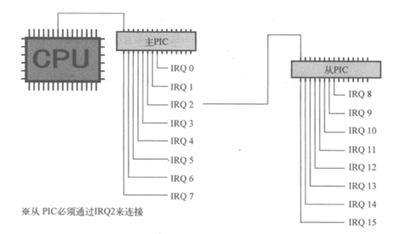
The 8259 Programmable Interrupt Controller (PIC) is one of the most important chips making up the x86 architecture. Without it, the x86 architecture would not be an interrupt driven architecture. The function of the 8259A is to manage hardware interrupts and send them to the appropriate system interrupt. This allows the system to respond to devices needs without loss of time (from polling the device, for instance).
由于CPU的结构限制, 只能处理一个中断, 所以PIC被设计来辅助CPU处理多个中断, PIC的全称是可编程中断控制器, 结构如图, 通过PIC可以控制15个中断, 在现代操作系统中, 8259PIC似乎被APIC所取代.
主触发器连接着CPU的管脚, 从触发器连接着主触发器的IRQ 2.
IRQ x 负责传导中断信号.
- 初始化PIC(边沿触发模式什么的让我想起了数字逻辑…):
-
PIC的触发器:
IMR 是中断屏蔽寄存器, 用来屏蔽IRQ信号;
ICW 1 和ICW 4 声明了主板配线方式( = = 完全不懂哎);
ICW 3 是主从设定, 表示触发器的哪一位连着从触发器; (一般是IRQ2 啦);
ICW 2 决定IRQ以哪一个中断号通知CPU, INT 0x0~0x19 不能被使用.
总的代码如下:
void init_pic(void)
    /* PIC初始化*/
{
    io_out8(PIC0_IMR, 0xff ); //禁止主PIC的所有中断
    io_out8(PIC1_IMR, 0xff ); //禁止从PIC的所有中断

    // 主PIC设定
    io_out8(PIC0_ICW1, 0x11 ); //边沿触发模式 (edge trigger mode)
    io_out8(PIC0_ICW2, 0x20 ); //IRQ0~7 由 INT 20~27 接收
    io_out8(PIC0_ICW3, 1 << 2); //PIC1从PIC由IRQ2 连接
    io_out8(PIC0_ICW4, 0x01 ); //无缓冲区模式

    //从PIC设定
    io_out8(PIC1_ICW1, 0x11 ); //边沿触发模式 (edge trigger mode)
    io_out8(PIC1_ICW2, 0x28 ); // IRQ0~7 由 INT 28~2f 接收
    io_out8(PIC1_ICW3, 2 ); //PIC1由IRQ2 连接
    io_out8(PIC1_ICW4, 0x01 ); //无缓冲区模式
    io_out8(PIC0_IMR, 0xfb ); //11111011 PIC1 以外全部禁止
    io_out8(PIC1_IMR, 0xff ); //11111111 禁止所有中断
    return;
}
-
ISR
ISR (Interrupt Service Routines) 是中断处理程序, 当发生中断的时候, 这段程序会被调用.注意ISR的返回不能够用RET指令, 而是用IRETD, 而IRETD指令在C语言里没有相应的实现, 当然有许多方法来规避这个问题, 作者用的是在汇编实现的函数里在调用C语言实现的函数.
写法暂时略过.
-
IDT
The Interrupt Descriptor Table (IDT) is specific to the I386 architecture. It is the Protected mode counterpart to the Real Mode Interrupt Vector Table (IVT) telling where the Interrupt Service Routines (ISR) are located. It is similar to the Global Descriptor Table in structure. The IDT entries are called gates. It can contain Interrupt Gates, Task Gates and Trap Gates.
IDT是一个保护模式下的中断描述符表, 用来告诉CPU ISR的位置, 结构和GDT相似, IDT的Entry也被称作门, 包括了中断门, 陷阱门和任务门…此处用的应是中断门.
set_gatedesc(idt + 0x21, (int) asm_inthandler21, 2 * 8, AR_INTGATE32);
set_gatedesc(idt + 0x27, (int) asm_inthandler27, 2 * 8, AR_INTGATE32);
set_gatedesc(idt + 0x2c, (int) asm_inthandler2c, 2 * 8, AR_INTGATE32);
其他函数的实现方法与GDT类似, 略过不表.
这次主要的是概念理解而不是代码编写, 界面也没有发生显著的变化, 因此不贴代码和图片了.