
【探索之路】机器人篇(5)-Gazebo物理仿真环境搭建_让机器人运动起来
如果完成了前两步,那么其实我们已经可以去连接我们的现实中的机器人了。
但是,做机器人所需要的材料还没有到,所以我们这里先在电脑平台上仿真一下。这里我们用到的就算gazebo物理仿真环境,他能很好的和ROS结合来帮助我们学习。
如果您安装的是ROS完整版并使用的是ubuntu 桌面版的话,gazebo其实已经安装到电脑中了。
什么是Gazebo?
Gazebo是一款优秀的开源仿真平台,可以实现动力学仿真、传感器仿真等。它能够模拟复杂和现实的环境中关节型机器人,能为机器人模型添加现实世界的物理性质。Gazebo里有force,physics的选项,可以为机器人添加例如重力,阻力等,Gazebo有一个很接近真实的物理仿真引擎,要记得一般的地面是没有阻力的,和现实世界有区别。
具体有关Gazebo的介绍和使用以及如何安装可以参考博文: 机器人仿真软件Gazebo介绍
使用Gazebo进行仿真的步骤
配置机器人模型
第一步:为link添加惯性参数和碰撞属性。因为是物理仿真,所以我要给我们的模型这些物理参数。
<visual>
</visual>
第二步:为link添加爱gazebo标签
第三步:为joint添加传动装置
<!-- Transmission is important to link the joints and the controller -->
<transmission name="${prefix}_wheel_joint_trans">
<type>transmission_interface/SimpleTransmission</type>
<joint name="${prefix}_wheel_joint" >
<hardwareInterface>hardware_interface/VelocityJointInterface</hardwareInterface>
</joint>
<actuator name="${prefix}_wheel_joint_motor">
<hardwareInterface>hardware_interface/VelocityJointInterface</hardwareInterface>
<mechanicalReduction>1</mechanicalReduction>
</actuator>
</transmission>
第四步:添加gazebo控制器插件
部分参数解释:
<robotNamespace>: 机器人的命名空间
<leftJoint>和<<rightJoint>>: 左右轮转动的关节joint
<wheelSeparation> 和 <wheelDiameter>: 机器人模型的相关尺寸,在计算差速参数时需要用到
<commandTopic>: 控制器订阅的速度控制话题,生成全局命名时要结合<robotNamespace>中设置的命名空间
<odometryFrame>: 里程计数据的参考坐标系,一般命名为odom
下面是我的代码:
<?xml version="1.0" ?>
<robot name="mwRobot"  xmlns:xacro="http://www.ros.org/wiki/xacro">

    <!--  No Chinese annotations exist.  -->

    <!-- PROPERTY LIST -->
    <xacro:property name="M_PI" value="3.1415926"/>
    <xacro:property name="base_radius" value="0.40"/>
    <xacro:property name="base_height" value="0.725"/>
    <xacro:property name="base_mass"   value="20.0"/>

    <xacro:property name="wheel_radius" value="0.095"/>
    <xacro:property name="wheel_length" value="0.015"/>
    <xacro:property name="wheel_joint_y" value="0.16305"/>
    <xacro:property name="wheel_joint_z" value="0.025"/>
    <xacro:property name="wheel_mass"   value="2.0"/>

    <xacro:property name="caster_radius" value="0.050"/> <!-- wheel_radius - ( base_length/2 - wheel_joint_z) -->
    <xacro:property name="caster_length" value="0.03"/>
    <xacro:property name="caster_joint_x" value="0.1305"/>
    <xacro:property name="caster_joint_z" value="0.0475"/>
    <xacro:property name="caster_mass"   value="0.03"/>

    <!-- Defining the colors used in this robot -->
    <material name="yellow">
        <color rgba="1 0.4 0 1"/>
    </material>
    <material name="black">
        <color rgba="0 0 0 0.95"/>
    </material>
    <material name="gray">
        <color rgba="0.75 0.75 0.75 1"/>
    </material>

    <material name="base_color">
        <color rgba="0.70 0.70 0.70 1"/>
    </material>

    <material name="wheel_color">
        <color rgba="0.30 0.30 0.30 1"/>
    </material>

    <material name="caster_color">
        <color rgba="0.20 0.20 0.20 1"/>
    </material>

    <xacro:macro name="wheel" params="prefix reflect angle">
        <!-- The connection between the wheel and the main body -->
        <joint name ="${prefix}_wheel_joint" type="continuous">
            <origin xyz="0 ${reflect*wheel_joint_y} ${-wheel_joint_z}" rpy="0 0 0" />
            <parent link="base_link"/>
            <child link="${prefix}_wheel_link"/>
            <axis xyz="0 1 0"/>
        </joint>

        <!-- The definition of the wheel -->
        <link name="${prefix}_wheel_link">
            <visual>
                <origin xyz="0 0 0" rpy="${M_PI/2} 0 ${angle}" />
                <geometry>
                    <mesh filename="package://mwRobot_description/meshes/${prefix}_wheel_link.STL" />
                </geometry>
                <material name="wheel_color"/>
            </visual>
            <collision>
                <origin xyz="0 0 0" rpy="${M_PI/2} 0 ${angle}" />
                <geometry>
                    <mesh filename="package://mwRobot_description/meshes/${prefix}_wheel_link.STL" />
                </geometry>
            </collision>
            <inertial>
                <origin xyz="0 0 0" />
                <mass value="${wheel_mass}" />
                <inertia  ixx="${wheel_mass*(3*wheel_radius*wheel_radius+wheel_length*wheel_length)/12}" ixy="0.0"  ixz="0.0"
                          iyy="${wheel_mass*(3*wheel_radius*wheel_radius+wheel_length*wheel_length)/12}"  iyz="0.0"
                          izz="${wheel_mass*(wheel_radius*wheel_radius)/2}" />
            </inertial>
        </link>
        <gazebo reference="${prefix}_wheel_link">
            <material>Gazebo/Black</material>
        </gazebo>

         <!-- Transmission is important to link the joints and the controller -->
        <transmission name="${prefix}_wheel_joint_trans">
            <type>transmission_interface/SimpleTransmission</type>
            <joint name="${prefix}_wheel_joint" >
                <hardwareInterface>hardware_interface/VelocityJointInterface</hardwareInterface>
            </joint>
            <actuator name="${prefix}_wheel_joint_motor">
                <hardwareInterface>hardware_interface/VelocityJointInterface</hardwareInterface>
                <mechanicalReduction>1</mechanicalReduction>
            </actuator>
        </transmission>
    </xacro:macro>

    <xacro:macro name="caster" params="prefix reflect">
        <!--  Joint of universal wheel and main body -->
        <joint name ="${prefix}_caster_joint" type="continuous">
            <origin xyz="${reflect*caster_joint_x} 0 ${-caster_joint_z}" rpy="0 0 0" />
            <parent link="base_link"/>
            <child link="${prefix}_caster_link"/>
            <axis xyz="0 1 1"/>
        </joint>

        <!-- Definition of universal wheel -->
        <link name="${prefix}_caster_link">
            <visual>
                <origin xyz="0 0 0" rpy="${M_PI/2} 0 0" />
                <geometry>
                    <mesh filename="package://mwRobot_description/meshes/caster_link.STL" />
                </geometry>
                <material name="caster_color"/>
            </visual>

            <collision>
                <origin xyz="0 0 0" rpy="${M_PI/2} 0 0" />
                <geometry>
                    <mesh filename="package://mwRobot_description/meshes/caster_link.STL" />
                </geometry>
            </collision>
            <inertial>
                <origin xyz="0 0 0" />
                <mass value="${caster_mass}" />
                <inertia  ixx="${caster_mass*(3*caster_radius*caster_radius+caster_length*caster_length)/12}" ixy="0.0"  ixz="0.0"
                          iyy="${caster_mass*(3*caster_radius*caster_radius+caster_length*caster_length)/12}"  iyz="0.0"
                          izz="${caster_mass*(caster_radius*caster_radius)/2}" />
            </inertial>
        </link>
        <gazebo reference="${prefix}_caster_link">
            <material>Gazebo/Black</material>
        </gazebo>
    </xacro:macro>

    <!-- Robot main body -->
    <xacro:macro name="mwRobot_MainPart">

        <!--  The joints between robots and his shadow  -->
        <joint name="base_footprint_joint" type="fixed">
            <origin xyz="0 0 0.0725" rpy="0 0 0" />
            <parent link="base_footprint"/>
            <child link="base_link" />
        </joint>

        <!--  Projection of robot body on the ground  -->
        <link name="base_footprint">
            <visual>
                <origin xyz="0 0 0" rpy="0 0 0" />
                <geometry>
                    <box size="0.001 0.001 0.001" />
                </geometry>
            </visual>
        </link>
        <gazebo reference="base_footprint">
            <turnGravityOff>false</turnGravityOff>
        </gazebo>

        <link name="base_link">
            <visual>
                <origin xyz="0 0 0" rpy="0 0 ${M_PI/2}" />
                <geometry>
                    <mesh filename="package://mwRobot_description/meshes/base_link.STL" />
                </geometry>
                <material name="base_color"/>
            </visual>
            <collision>
                <origin xyz="0 0 ${base_height/3}" rpy="0 0 ${M_PI/2}" />
                <geometry>
                    <mesh filename="package://mwRobot_description/meshes/base_link.STL" />
                </geometry>
            </collision>
            <inertial>
                <origin xyz="0 0 ${base_height/3}" />
                <mass value="${base_mass}" />
                <inertia  ixx="${base_height*base_mass*base_radius/18.0}" ixy="0.0"  ixz="0.0"
                          iyy="${base_height*base_mass*base_radius/18.0}"  iyz="0.0"
                          izz="${base_height*base_mass*base_radius/18.0}" />
            </inertial>
        </link>

        <gazebo reference="$base_link">
            <material>Gazebo/Gray</material>
        </gazebo>

        <wheel prefix="left" reflect="-1" angle="${M_PI}"/>
        <wheel prefix="right" reflect="1" angle="0"/>

        <caster prefix="front" reflect="-1"/>
        <caster prefix="back" reflect="1"/>

        <!-- controller -->
        <gazebo>
            <plugin name="differential_drive_controller"
                    filename="libgazebo_ros_diff_drive.so">
                <rosDebugLevel>Debug</rosDebugLevel>
                <publishWheelTF>true</publishWheelTF>
                <robotNamespace>/</robotNamespace>
                <publishTf>1</publishTf>
                <publishWheelJointState>true</publishWheelJointState>
                <alwaysOn>true</alwaysOn>
                <updateRate>100.0</updateRate>
                <legacyMode>true</legacyMode>
                <leftJoint>left_wheel_joint</leftJoint>
                <rightJoint>right_wheel_joint</rightJoint>
                <wheelSeparation>${wheel_joint_y*2}</wheelSeparation>
                <wheelDiameter>${2*wheel_radius}</wheelDiameter>
                <broadcastTF>1</broadcastTF>
                <wheelTorque>30</wheelTorque>
                <wheelAcceleration>1.8</wheelAcceleration>
                <commandTopic>cmd_vel</commandTopic>
                <odometryFrame>odom</odometryFrame>
                <odometryTopic>odom</odometryTopic>
                <robotBaseFrame>base_footprint</robotBaseFrame>
            </plugin>
        </gazebo>

    </xacro:macro>

</robot>
创建仿真环境
首先,我们需要在launch文件中修改配置来启动gazebo并加载我们的模型。
以下是我launch文件的内容。
<!-- 利用urdf建立模型 -->
<launch>

    <!-- 设置launch文件的参数 -->
    <arg name="paused" default="false" />
    <arg name="use_sim_time" default="true" />
    <arg name="gui" default="true" />
    <arg name="headless" default="false" />
    <arg name="debug" default="false" />

    <!-- 运行gazebo仿真环境 -->
    <include file="$(find gazebo_ros)/launch/empty_world.launch">
        <arg name="debug" value="$(arg debug)" />
        <arg name="gui" value="$(arg gui)" />
        <arg name="paused" value="$(arg paused)" />
        <arg name="use_sim_time" value="$(arg use_sim_time)" />
        <arg name="headless" value="$(arg headless)" />
    </include>

    <arg name="model" default="$(find xacro)/xacro --inorder '$(find mwRobot_description)/urdf/gazebo/mwRobot_CompleteModel_gazebo.xacro'"/>
    <param name="robot_description" command="$(arg model)" />

    <!-- 显示关节控制插件,可以使关节回到中心位置也能设置关节为随机角度 -->
    <!-- param name="use_gui" value="true" / -->

    <!-- 运行joint_state_publisher节点,发布机器人的关节状态 -->
    <node name="joint_state_publisher_mwRobot" pkg="joint_state_publisher" type="joint_state_publisher" />

    <!-- 运行robot_state_publisher节点,将机器人各个links、joints之间的关系通过tf发布 -->
    <node name="mwRobot_state_publisher_mwRobot" pkg="robot_state_publisher" type="state_publisher" />

    <!-- 运行rviz可视化界面 -->
    <node name="urdf_spawner" pkg="gazebo_ros" type="spawn_model" respawn="false" output="screen"
        args="-urdf -model mwRobot -param robot_description"/>

</launch>
然后我们运行启动新的launch文件。
但是会发现启动失败,这其实是因为Gazebo启动的时候尝试从 http://models.gazebosim.org/ 下载世界模型,但是没有成功所导致的。。。
解决方法如下:
在终端中运行如下命令:
$ wget -r -R "index\.html*" http://models.gazebosim.org/该命令会递归的下载http://models.gazebosim.org/ 目录下面的所有文件。
之后你会得到一个文件夹models.gazebosim.org,它几乎包含了你所需的所有的世界和机器人模型。 然后在终端运行
cd ~
mkdir -p .gazebo/models
最后,将文件夹models/gazebosim.org/下的所有目录剪切到 ~/.gazebo/models文件夹下面,再重新启动gazebo,系统就会成功的启动gazebo。
下载成功后,重新运行launch文件,将会启动成功。
roslaunch mwRobot_description display_mwRobot_CompleteModel_gazebo.launch
如下图所示:
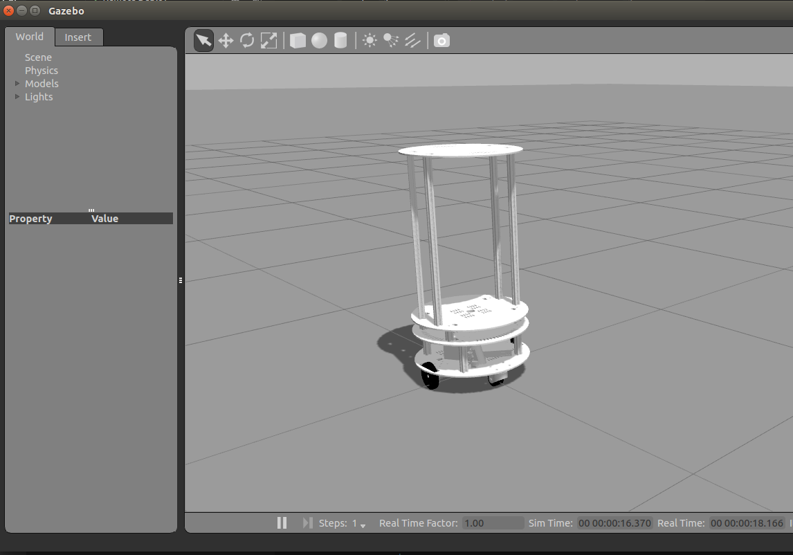

如上图所示,我们可以放置一些模型到仿真空间中。
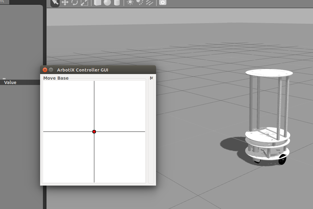
我们可以安装一些小工具来测试机器人能否移动。
sudo apt-get install ros-indigo-arbotix-*
sudo apt-get install ros-indigo-joystick-drivers
sudo apt-get install joystick
执行完上面的三句语句后,运行roslaunch运行仿真,然后在另一个终端启动arbotix_gui,即可打开一个仿真的摇杆界面,此时我们就可以控制机器人移动。
现在我们可以给地图添加模型了。
linux内核下载地址: https://www.kernel.org/pub/linux/kernel

