Software Architecture and High Level Design软件架构与概要设计
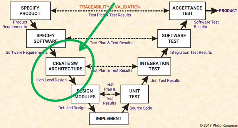
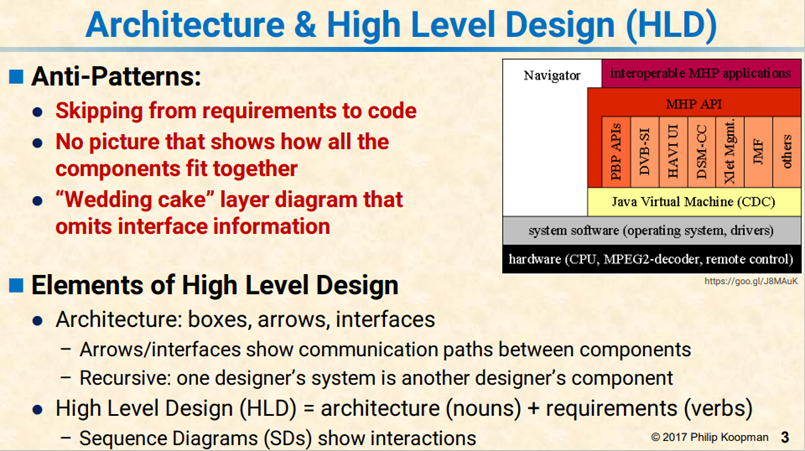
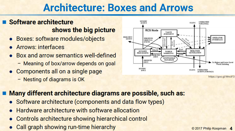
High Level Design in short HLD is the general system design means it refers to the overall system design. It describes the overall description/architecture of the application. It includes the description of system architecture, data base design, brief description on systems, services, platforms and relationship among modules. It is also known as macro level/system design. It is created by solution architect. It converts the Business/client requirement into High Level Solution. It is created first means before Low Level Design.
All the really important mistakes are made the first day.
– Eberhardt Rechtin, System Architecting
同时以下是一个软件设计文档模板:
System Design Standards | ||
Date: Oct 2020 | ||
Prepared By: | ||
Project: CAWS Standards Documentation | ||
Harvest Package Name: | ||
Harvest Version: | ||
Contract: N/A |
This section lists the various versions or releases of the document.
Version | Details/Description | Distribution | Date | Author |
Contents
Revision History............................................................................................................................................................. 1
<About this document>............................................................................................................................................... 5
<Ministry Standards>............................................................................................................................................... 5
1. Introduction........................................................................................................................................................... 6
1.1 Document Purpose....................................................................................................................................... 6
1.2 Audience......................................................................................................................................................... 6
1.3 System Overview........................................................................................................................................... 6
1.4 References...................................................................................................................................................... 7
1.5 Design Methodology.................................................................................................................................... 7
1.6 Quality Assurance......................................................................................................................................... 7
1.7 System Background...................................................................................................................................... 7
1.8 System Objectives......................................................................................................................................... 7
1.9 System Constraints....................................................................................................................................... 7
1.10 Measures of Success..................................................................................................................................... 8
1.11 Guiding Principles........................................................................................................................................ 8
1.12 <Revision of System Design to Match As-Built System>...................................................................... 8
2. System Architecture............................................................................................................................................ 8
2.1 Architectural Design.................................................................................................................................... 8
2.2 Decomposition Description......................................................................................................................... 8
2.3 Design Rationale........................................................................................................................................... 9
3. Process Design....................................................................................................................................................... 9
4. Data Design............................................................................................................................................................ 9
4.1 High-level Data Interactions...................................................................................................................... 9
4.2 Data Security................................................................................................................................................. 9
5. Human Interface Design.................................................................................................................................. 10
5.1 Overview...................................................................................................................................................... 10
5.2 Screens......................................................................................................................................................... 10
5.3 Reports......................................................................................................................................................... 12
5.4 Help............................................................................................................................................................... 13
5.5 Error Messages........................................................................................................................................... 13
6. Technical Requirements.................................................................................................................................. 13
6.1 Capacity....................................................................................................................................................... 13
6.2 Software........................................................................................................................................................ 14
6.3 Hardware..................................................................................................................................................... 14
6.4 Communication protocols......................................................................................................................... 14
6.5 Interoperability Requirements.................................................................................................................. 14
6.6 Performance................................................................................................................................................ 14
6.7 Hardware/Software Interfaces................................................................................................................. 15
Sign-Off.......................................................................................................................................................................... 16
Appendix A. Definitions, Acronyms, and Abbreviations................................................................................. 16
Appendix B. Screen Images...................................................................................................................................... 17
Appendix C. Report Layouts................................................................................................................................... 17
Appendix D. Known Issues....................................................................................................................................... 17
<This document is the standard template for Design Specification documents. Text enclosed in angle brackets (< >) are comments that would not be included in an actual Design Specification.
The contents of this document are based upon the concepts espoused in the document “IEEE Std 1016-1998 - Recommended Practice for Software Design Descriptions.”
The context of this document is directed primarily towards the design of .NET Web applications – this is the target architecture for custom applications being developed for the Ministry.
The system identified in the System Design document must be decomposed to the point where each subsystem is clearly identified and specify the extent to which subsystems depend on each other. In general, each subsystem should perform a single function.
It is expected that a logical system description and a physical system description be included. By this we mean that:
- Logical System Description is a description of a system that focuses on the system’s function and purpose without regard to how the system will be physically implemented.
- Physical System Description is a description of a system that focuses on how the system will be materially constructed.
It is also expected that the completed document be concise and clear, with an effort to eliminate vagueness and unnecessary verbiage. Finally, it is expected that the Systems Design document will receive one final revision following system build to describe the as-built system.>
<The standards mentioned in this document may change without notice. It is the responsibility of the vendor to confirm current standards with the Ministry.
Any exceptions to the standards must have prior written approval of the Ministry’s Technical Architect
Complete exemption from using this System Design Standards template must be attained by the Director, ISB.>
1. Introduction
<The Introduction section provides an overview of the Design Specifications and the scope of the system.>
1.1 Document Purpose
<Define the purpose of the Design Specifications document.>
This document describes the system design specifications for the <name of system>. It describes how the application will be constructed by specifying the components to be used, how they will be organized in relation to each other, and the general principles of the application's internal construction.
This document also serves as a systems reference manual for the running system once it is implemented, and is the primary reference for application migrations, support and maintenance.
<The description must go beyond detailed requirements to cover physical design. The description must be sufficiently detailed to enable a project team to build the system without any further breakdown and for support staff to understand the running system in its environment once the system becomes operational.>
1.2 Audience
The intended audience for the document is technically proficient, but does not necessarily have specific knowledge of the business areas involved.
During application development and implementation, it will be used primarily by:
- Ministry staff responsible for approval of the <system’s> specifications, presentation standards, intended architecture, security, and deployment context;
- Development staff responsible for developing, documenting, and delivering the <system> application.
After implementation, it will serve as the authoritative description of the application as built, and will be used primarily by operations and maintenance staff.
1.3 System Overview
<This section provides an overview of the system. Specifically, it will:
- Explain what the proposed system will and will not do
· Describe relevant benefits, objectives and goals as precisely as possible
· Provide a context diagram for the system (if useful to readers), clearly delineating the sub-systems in-scope and out-of-scope
The description of scope must be consistent with higher-level project documents (e.g. Project Charter, Project Plan).>
Any/all references to “the system” will relate to the contents of this section.
1.4 References
<List any documents referenced in Design Specifications document, such as:
· Project Charter
· Project Plan
· Requirements document
· Documentation of whiteboard session outcomes and decisions
· Change requests
Include the version number of each document and the URL of any document repositories.>
1.5 Design Methodology
<List the approaches that the design of this system will follow.>
<The SDLC standards as currently published are based upon a “waterfall” methodology. Variation from these standards requires prior written permission from the Ministry’s Technical Architect.>
1.6 Quality Assurance
<Please describe the Quality Assurance processes applied to this project, Include vendor and Ministry process. The vendor must have a quality assurance process in place that meets accepted UAT standards (e.g. IEEE Std 730 - IEEE Standard for Software Quality Assurance Plans). The vendor must review all code before submitting the application to the Ministry. Once received by the Ministry, the application will be reviewed by the Ministry to ensure that the relevant standards have been met. These quality assurance processes include, but are not limited to, the following:
Standards, practices, conventions, and metrics;
- Reviews and audits;
- Testing;
- Problem reporting and corrective action;
- Tools, techniques, and methodologies;
- Source Code control.>
1.7 System Background
<Describe the business background of the system, the business requirements for initiating the project, the history of any predecessor systems or closely related systems. >
1.8 System Objectives
<Describe the high-level objectives of the application and list subsidiary goals that will achieve each objective. >
1.9 System Constraints
<Identify any business or system constraints or exemptions from the Ministry that will impact the manner in which the software is to be:
- specified
- designed
- implemented, or
- tested.>
1.10 Measures of Success
<Describe one or more approaches for the determining success of the application, including quantitative or qualitative metrics.>
1.11 Guiding Principles
<Identify where design was based on existing implementations, best practices, etc, if any, that describes the underlying design of the application. The purpose of these guiding principles is to clarify the reader’s understanding of the application’s design.>
1.12 <Revision of System Design to Match As-Built System>
<The system design document provides a blueprint for system build. Following deployment, the System Design acts as the application systems reference manual for application support.
During the course of build, some changes may be made in consultation with Ministry Infrastructure or Architecture staff. At the end of the build phase, the vendor will perform a final revision of the System Design document to match the system as-built.>
2. System Architecture
<This section discusses the system architecture aspect of the application’s design.
The discussion has two parts:
1. The application as it relates to computer systems that exist independent of the application (Section Architectural Design);
2. A decomposition of the application to show its minimum constituent parts as they will appear in the implementation (Section Decomposition Description).>
2.1 Architectural Design
<The Architectural Design section describes the detailed system architecture, and the fundamental technical structure of the software components and the interfaces between them. It must include a description of the proposed deployment environment and major user categories (e.g., internal and external). This may be supplemented by diagrams where appropriate.>
2.2 Decomposition Description
<This section further decomposes the System Architecture to its constituent parts, in order to show the fundamental technical structure of the subsystems. The developer may elaborate within this structure, but the development must be constrained by these structural principles. >
2.2.1 Data Access Model
<Describe the overall design that will govern access to the persistent data layer. This section must address all types of access and data distribution, whether to the end user, or to an external application.>
2.2.2 Application Security Model
<Describe the authentication and authorization models that apply consistently throughout the application. The model must be based upon existing standards defined in the Oracle Designer 10g standards and guidelines, and the roles must be listed and described in this section.
For .NET based applications that require user authentication, the design proposed must employ the use of the BC Government Common Log-on Page (CLP), which uses Netegrity SiteMinder for user authentication..>
2.2.3 Domain Model
<Describe the high-level class model. Where appropriate, list the Class to the Database Table/View mapping and include as an Appendix.>
2.3 Design Rationale
<Discuss the rationale for any major design decisions that may not be obvious to the target audience.>
3. Process Design
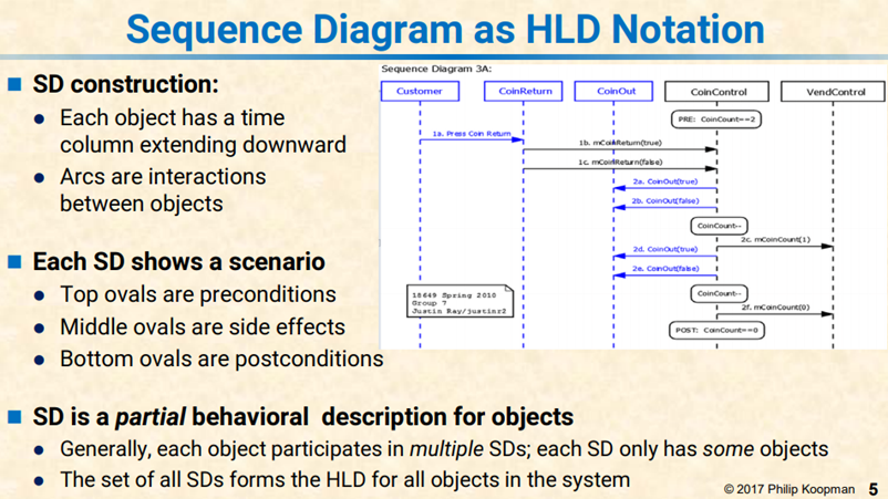
<This is the section where the business transaction designs are documented, such as interactions between software components. The description could employ UML diagrams where appropriate.>
4. Data Design
<This section is intended to describe the application’s interaction with the database with an emphasis on Data Security... This must include the Crud Matrix and application database roles required to support the data security framework.
NOTE: The Server Model and Data Conversion deliverables are NOT included in this section, however they may be referenced if necessary. These would be separate deliverables which when approved along with the Design Document would constitute formal approval of the Design Phase of the SDLC.>
4.1 High-level Data Interactions
<Identify all data repositories used in the application, highlighting key features such as security features, data validation, and report parameters. >
4.2 Data Security
<Describe the database security and authorization features including implementation of the data access matrix. Enumerate and describe the roles, or types of users, that may access the application. Note any special cases, such as those involving sensitive or restricted data. This covers both application security and direct-connect security.>
5. Human Interface Design
<This discussion addresses the functionality required by the application's users and how the application will support this functionality through its implementation. It should not specify the tools used to create the interface.
In this section you must cover the following topics (if applicable):
- Screen and Form Design
- Report Design
- Application Screen Flow Design>
5.1 Overview
<Summarize the application’s human interface, highlighting key features. It is not necessary to include every screen and report.>
5.1.1 Application Screen Flow Design
<Provide a high level hierarchical view of how the screens interrelate with one another.>
5.2 Screens
<Note:
Sections 5.2.1 to 5.2.4 must be repeated sequentially for each new and modified screen that appears in the system. Any requests to exclude screens/sections must be approved by the Ministry’s Technical Architect.>
DEFINITIONS: The following describe the purpose of each column in the data elements grids for section 5.2.X and 5.3.X
Screen Element: Descriptive name of the Screen Element
Label: Label Name as it appears on the screen
Behaviour: Describe normal behaviour associated with screen element (eg Clears all text fields, or Validates and saves data and Navigates to previous screen, etc)
Tab Order: Numeric Value of Tab order for screen
Required: Y/N
Unique Y/N
Format Specific input formatting (eg dd/mmm/yyyy or aa@aa.aa, min/max length, $0.00, etc)
Source Lists the source of data presented or input (eg DB field from which values are sourced, or user for user input, N/A, etc)
Destination Lists the destination of data presented or input (eg DB field where entered values will be saved, N/A for read only, etc)
Type: Element Type (eg date, string, integer, double)
Special Behaviour: List special behaviours not already covered in previous columns (eg specific associated business rules, data validation rules, calculations, etc)
5.2.1 Screen Description
Screen Identifier | |
Screen Name | |
Purpose | . |
Supporting Documentation (Requirements) | |
Supporting Documentation (Use Cases) | |
Supporting Documentation (Testing) | |
Assumptions | |
Outstanding Issues[1] |
5.2.2 Screen Image
<Display facsimiles of screen images used in the application.>
5.2.3 Screen/Form Objects and Actions
<Describe the flow of control through screen objects.
All Boxes must be filled in for all screen objects>
Screen Element | Label | Behaviour | Tab Order | Type | Special Behaviour |
5.2.4 Data Elements
<All Boxes must be filled in for all screen elements (excluding static content), not already covered in 5.2.3 Screen Objects and Actions>
Screen Element | Label | Behaviour | Tab Order | Required | Unique | Format | Source | Destination | Type | Special Behaviour |
Special Behaviours Listed here:
5.3 Reports
<Note:
Sections 5.3.1 to 5.3.3 must be repeated sequentially for each new and modified report that exists in the system. Any requests to exclude reports/sections must be approved by the Ministry Technical Architect.>
5.3.1 Report Description
Report Identifier | |
Report Name | |
Purpose | . |
Supporting Documentation (Requirements) | |
Supporting Documentation (Use Cases) | |
Supporting Documentation (Testing) | |
Assumptions | |
Outstanding Issues[2] |
5.3.2 Report Image
<Display facsimiles of Report images used in the application>
5.3.3 Data Elements
<All Boxes must be filled in>
Report Element | Label | Behaviour | Format | Source | Type | Special Behaviour |
Special Behaviours Listed here:
5.4 Help
<Describe the application’s online help system.>
5.5 Error Messages
<Specify guidelines for writing and displaying error messages associated with the application. It is unnecessary to document all error messages.>
6. Technical Requirements
<This discussion addresses the technical issues affecting the application. This includes the specification of how the system will satisfy non-functional requirements arising from the technical environment of the application. These include external systems, support libraries, anticipated load, and deployment procedures.>
6.1 Capacity
<This section describes relevant capacity issue for the application. If appropriate these may be broken down by hardware component (e.g., web server capacity, data server capacity, etc.). Non-applicable subsections may be deleted.>
6.1.1 CPU usage
< This section describes CPU requirements. Both database CPU and webserver CPU requirements must be described Provide a description of the expected usage, explaining activities associated with high usage.>
6.1.2 Disk space
<This section describes disk storage requirements. Both database storage and file-system storage requirements must be described. Provide a description of disk space requirements as well as an estimate of future storage requirements.>
6.1.3 Concurrent usage
<Estimate the number of concurrent users and their usage levels, including average and maximum peak.>
6.1.4 Database Performance
<Define database performance standards, both qualitative. Performance requirements must provide an estimate of throughput expressed as Transactions per Second (TPS) and target response times for representative transactions.>
6.2 Software
< Define the software requirements for the application. The Ministry provides a list of software in the Application Development Environment standards that encompasses the supported software environment. The design proposed must conform to this environment
If the application requires features of Oracle Enterprise Edition (rather than Oracle Standard Edition), list these features in this section.>
6.2.1 Server software
<As per the Ministry Application Development Environment standards.NET applications will typically be deployed under IIS running on a Windows server.
If the application requires a non-standard server operating system, describe and justify the deviations.>
6.2.2 Software Dependencies
<List all of the software dependencies and their versions, including support libraries plug-ins, and 3rd party controls. This includes both dependencies on software you assume to exist and software that you wish to include. For each software dependency identify whether it is a ministry standard as identified in the Application Development Environment Standards. Use of any non-standard components requires prior written approval by the Ministry Technical Architect.>
6.3 Hardware
<If the application requires a non-standard hardware, describe and justify the requirements.>
6.4 Communication protocols
< This section must identify all TCP/IP based communication requirements.>
6.5 Interoperability Requirements
<Describe the implementation of any interoperability requirements, listing system interfaces and citing standards and versions.>
6.6 Performance
<Define performance standards for the application, and describe factors affecting performance. It must define performance metrics for the application as a whole. It should define performance metrics (e.g. “10,000 transactions per hour with an average size per transaction of 65 KB”). This section must identify end-to-end performance requirements; database performance requirements should be identified in Section 6.1.4.>
6.7 Hardware/Software Interfaces
<List any hardware or software interfaces used by the application. The information provided should complement previously provided information but should not duplicate the information.
Each specific interface must be identified, including inputs and outputs and the purpose of the interface should be described. This includes the reading from, or writing to, of files on disk. Directory and file permissions, if applicable, should be documented here.>
Sign-Off
<Commencing on a new page, the last section of the document must be a sign-off page where appropriate members of the Ministry and contract team can accept and approve the System Design deliverable.>
Name | Signature | Date | |
Vendor Project Manager | |||
Name | Signature | Date | |
Ministry Project Manager | |||
Name | Signature | Date | |
Technical Architect | |||
Name | Signature | Date | |
Program Area Representative | |||
Name | Signature | Date | |
Program Area Representative | |||
Appendix A. Definitions, Acronyms, and Abbreviations
<Provide a list of all acronyms and abbreviations used in the document, other than the very obvious (e.g., “BC”, “IBM”). Include definitions of any terms that may not be clear to parts of the primary or secondary audiences.>
<Provide a complete listing of the application Screen Images.>
<Provide a complete listing of the application Report Layouts.>
<This appendix is used to track known deficiencies in the design document, in the application, or in the data architecture. For example, if the application uses an unapproved non-standard component, this is a deficiency in the application. If the design document lacks adequate detail in a section and this has not been rectified, then this is a design document deficiency. Deficiencies are expected to be addressed in subsequent releases of the operational system.>
今天先到这儿,希望对云原生,技术领导力, 企业管理,系统架构设计与评估,团队管理, 项目管理, 产品管管,团队建设 有参考作用 , 您可能感兴趣的文章:
领导人怎样带领好团队
构建创业公司突击小团队
国际化环境下系统架构演化
微服务架构设计
视频直播平台的系统架构演化
微服务与Docker介绍
Docker与CI持续集成/CD
互联网电商购物车架构演变案例
互联网业务场景下消息队列架构
互联网高效研发团队管理演进之一
消息系统架构设计演进
互联网电商搜索架构演化之一
企业信息化与软件工程的迷思
企业项目化管理介绍
软件项目成功之要素
人际沟通风格介绍一
精益IT组织与分享式领导
学习型组织与企业
企业创新文化与等级观念
组织目标与个人目标
初创公司人才招聘与管理
人才公司环境与企业文化
企业文化、团队文化与知识共享
高效能的团队建设
项目管理沟通计划
构建高效的研发与自动化运维
某大型电商云平台实践
互联网数据库架构设计思路
IT基础架构规划方案一(网络系统规划)
餐饮行业解决方案之客户分析流程
餐饮行业解决方案之采购战略制定与实施流程
餐饮行业解决方案之业务设计流程
供应链需求调研CheckList
企业应用之性能实时度量系统演变
如有想了解更多软件设计与架构, 系统IT,企业信息化, 团队管理 资讯,请关注我的微信订阅号:
作者:Petter Liu
出处:http://www.cnblogs.com/wintersun/
本文版权归作者和博客园共有,欢迎转载,但未经作者同意必须保留此段声明,且在文章页面明显位置给出原文连接,否则保留追究法律责任的权利。
该文章也同时发布在我的独立博客中-Petter Liu Blog。


![MegadotnetMicroMsg_thumb1_thumb1_thu[2] MegadotnetMicroMsg_thumb1_thumb1_thu[2]](http://images.cnitblog.com/blog/15172/201503/211054062506158.jpg)

