


详细介绍:STM32 GPIO-------设置成51单片机模式输出
2025-11-12 13:51 tlnshuju 阅读(0) 评论(0) 收藏 举报在做项目的过程中,我总感觉STM32 GPIO 电平的高低输出用函数时比较费时(敲代码费时),没有51单片机IO输出时的简单。在这里,我给出了STM32类似51单片机IO口输出的设置方式。
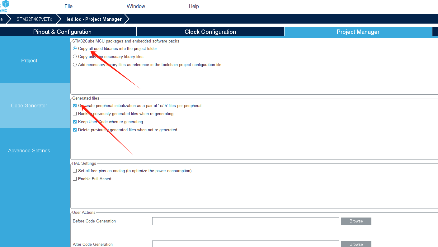
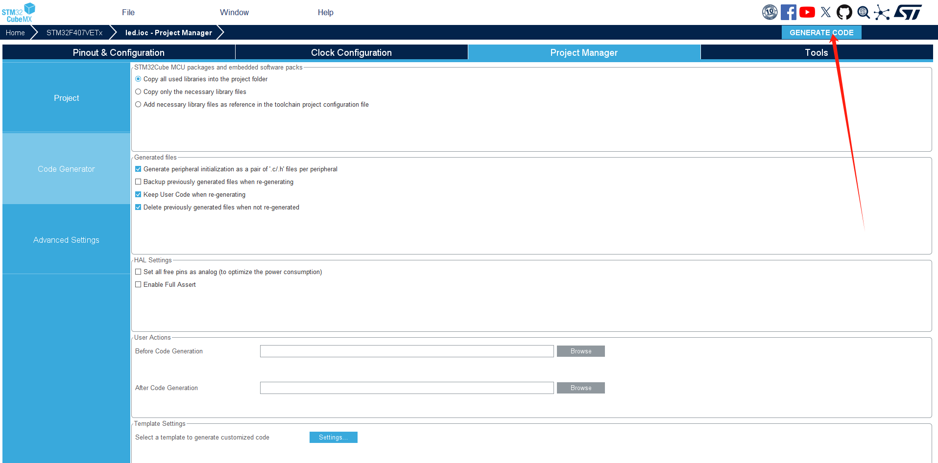
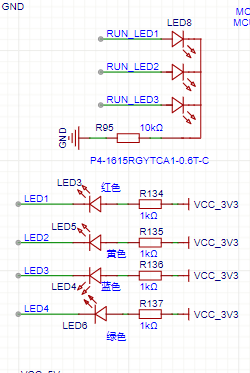
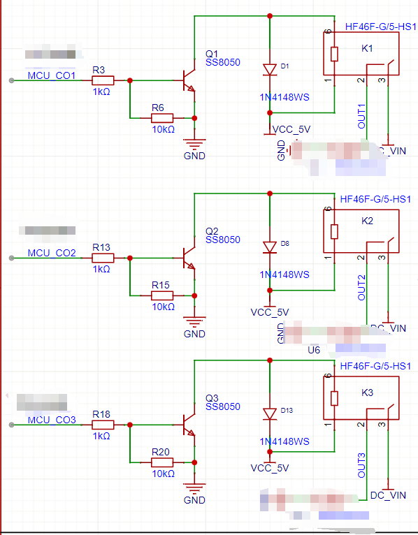
废话不多说,我直接上图及代码。写出的代码经过实际的实验,验证可行。

主函数代码
/* USER CODE BEGIN Header */
/**
******************************************************************************
* @file : main.c
* @brief : Main program body
******************************************************************************
* @attention
*
* Copyright (c) 2025 STMicroelectronics.
* All rights reserved.
*
* This software is licensed under terms that can be found in the LICENSE file
* in the root directory of this software component.
* If no LICENSE file comes with this software, it is provided AS-IS.
*
******************************************************************************
*/
/* USER CODE END Header */
/* Includes ------------------------------------------------------------------*/
#include "main.h"
#include "iwdg.h"
#include "tim.h"
#include "gpio.h"
/* Private includes ----------------------------------------------------------*/
/* USER CODE BEGIN Includes */
/* USER CODE END Includes */
/* Private typedef -----------------------------------------------------------*/
/* USER CODE BEGIN PTD */
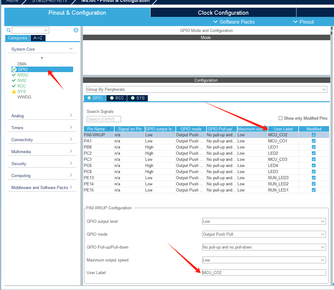
#define LED1(n) HAL_GPIO_WritePin(LED1_GPIO_Port, LED1_Pin, n);
#define LED2(n) HAL_GPIO_WritePin(GPIOC, LED2_Pin, n);
#define LED3(n) HAL_GPIO_WritePin(GPIOC, LED3_Pin, n);
#define LED4(n) HAL_GPIO_WritePin(GPIOC, LED4_Pin, n);
#define RUN_LED1(n) HAL_GPIO_WritePin(GPIOE, RUN_LED1_Pin, n);
#define RUN_LED2(n) HAL_GPIO_WritePin(GPIOE, RUN_LED2_Pin, n);
#define RUN_LED3(n) HAL_GPIO_WritePin(GPIOE, RUN_LED3_Pin, n);
#define CONTROL1(n) HAL_GPIO_WritePin(GPIOA, MCU_CO1_Pin, n);
#define CONTROL2(n) HAL_GPIO_WritePin(GPIOA, MCU_CO2_Pin, n);
#define CONTROL3(n) HAL_GPIO_WritePin(MCU_CO3_GPIO_Port, MCU_CO3_Pin, n);
/* USER CODE END PTD */
/* Private define ------------------------------------------------------------*/
/* USER CODE BEGIN PD */
/* USER CODE END PD */
/* Private macro -------------------------------------------------------------*/
/* USER CODE BEGIN PM */
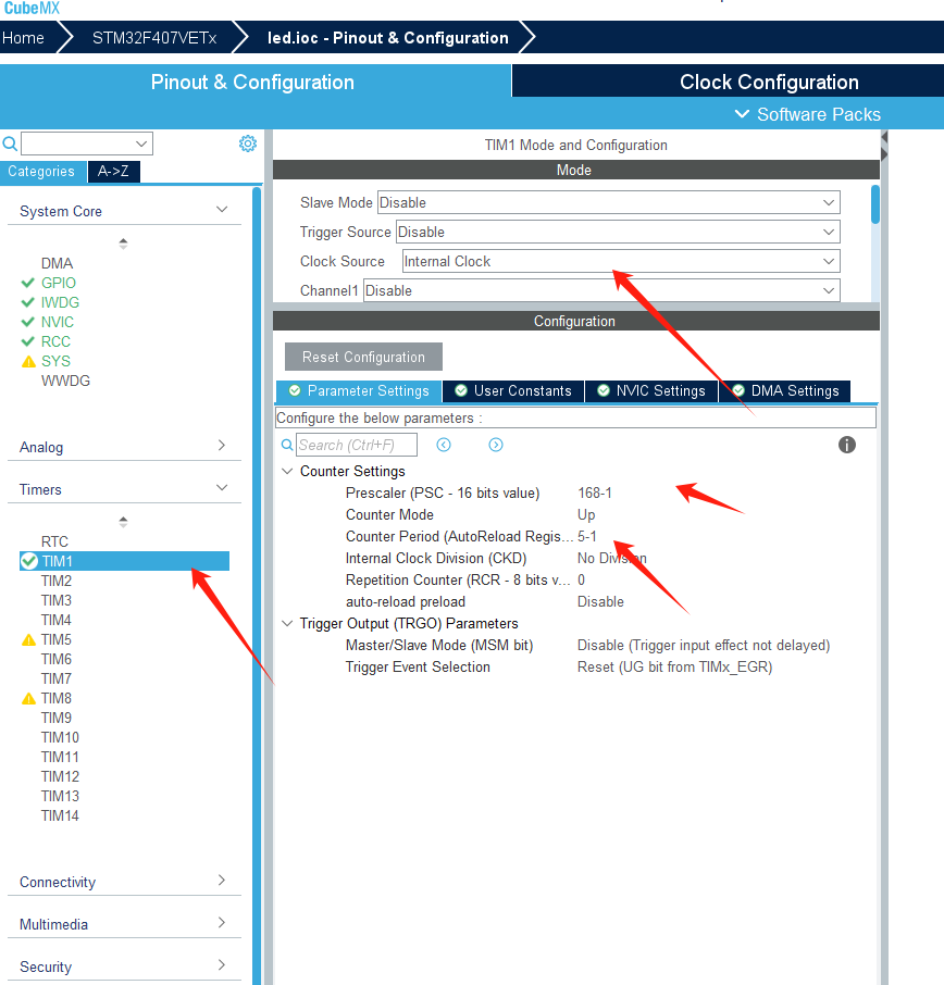
//定时器
#define TIME_HTIM htim1
//创建定时器计数
uint16_t timeCount;
/* USER CODE END PM */
/* Private variables ---------------------------------------------------------*/
/* USER CODE BEGIN PV */
/* USER CODE END PV */
/* Private function prototypes -----------------------------------------------*/
void SystemClock_Config(void);
/* USER CODE BEGIN PFP */
/* USER CODE END PFP */
/* Private user code ---------------------------------------------------------*/
/* USER CODE BEGIN 0 */
/* USER CODE END 0 */
/**
* @brief The application entry point.
* @retval int
*/
int main(void)
{
/* USER CODE BEGIN 1 */
uint8_t i=0;
uint16_t time_1s=0;
timeCount=0;
/* USER CODE END 1 */
/* MCU Configuration--------------------------------------------------------*/
/* Reset of all peripherals, Initializes the Flash interface and the Systick. */
HAL_Init();
/* USER CODE BEGIN Init */
/* USER CODE END Init */
/* Configure the system clock */
SystemClock_Config();
/* USER CODE BEGIN SysInit */
/* USER CODE END SysInit */
/* Initialize all configured peripherals */
MX_GPIO_Init();
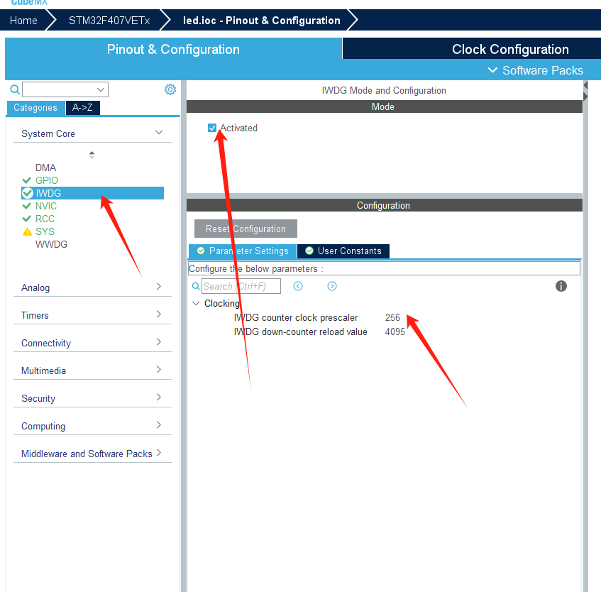
MX_IWDG_Init();
MX_TIM1_Init();
/* USER CODE BEGIN 2 */
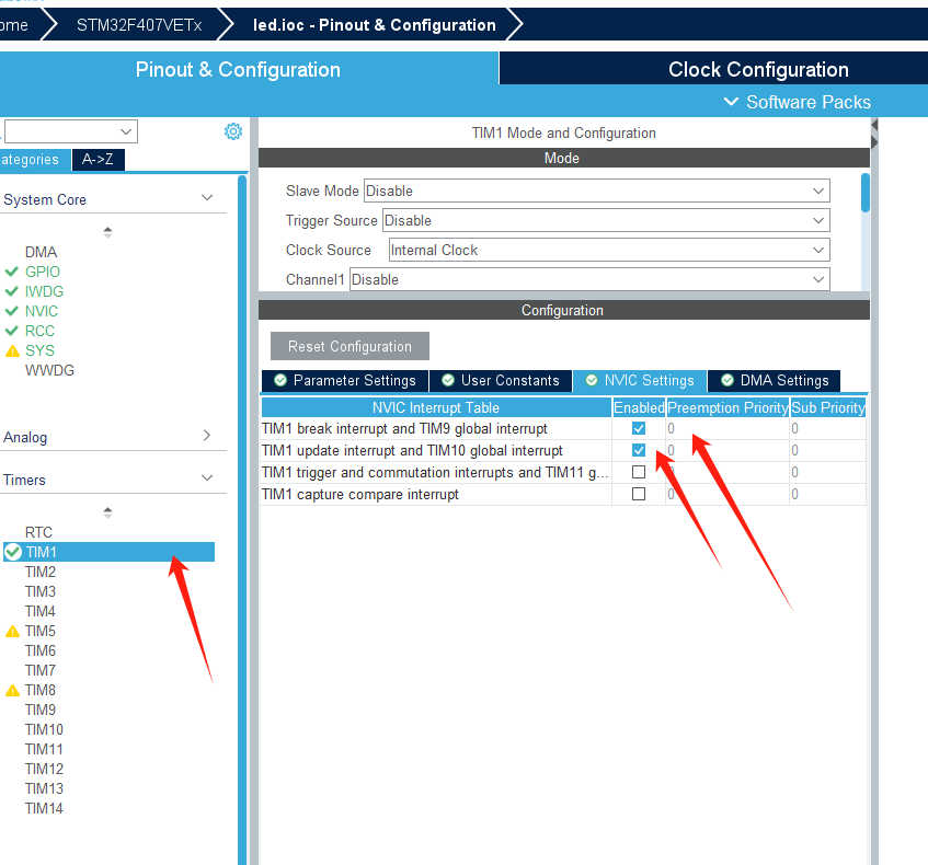
//开启定时器
HAL_TIM_Base_Start_IT(&TIME_HTIM);
//复位看门狗 喂狗
HAL_IWDG_Refresh(&hiwdg);
/* USER CODE END 2 */
/* Infinite loop */
/* USER CODE BEGIN WHILE */
while (1)
{
/* USER CODE END WHILE */
/* USER CODE BEGIN 3 */
//复位看门狗 喂狗
HAL_IWDG_Refresh(&hiwdg);
if(timeCount>=200)
{
timeCount=0;
time_1s++;
}
if(time_1s>=1000)
{
time_1s=0;
RUN_LED1(1-i);
i=1-i;
}
}
/* USER CODE END 3 */
}
/**
* @brief System Clock Configuration
* @retval None
*/
void SystemClock_Config(void)
{
RCC_OscInitTypeDef RCC_OscInitStruct = {0};
RCC_ClkInitTypeDef RCC_ClkInitStruct = {0};
/** Configure the main internal regulator output voltage
*/
__HAL_RCC_PWR_CLK_ENABLE();
__HAL_PWR_VOLTAGESCALING_CONFIG(PWR_REGULATOR_VOLTAGE_SCALE1);
/** Initializes the RCC Oscillators according to the specified parameters
* in the RCC_OscInitTypeDef structure.
*/
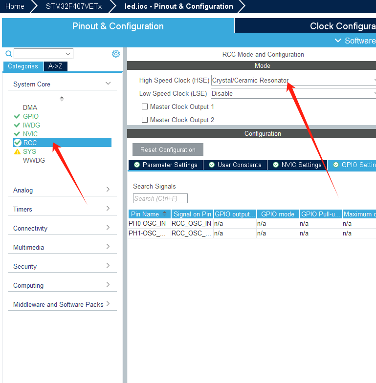
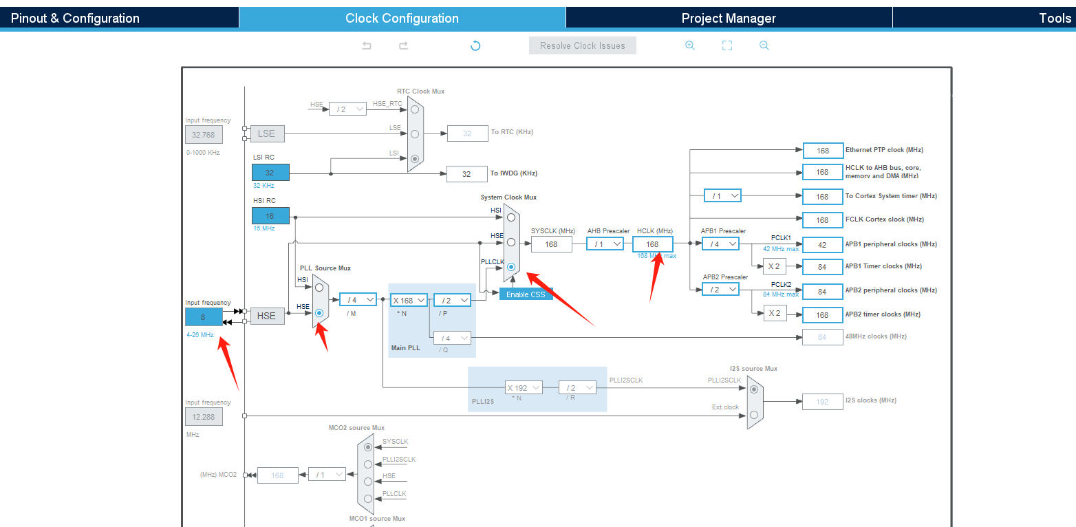
RCC_OscInitStruct.OscillatorType = RCC_OSCILLATORTYPE_LSI|RCC_OSCILLATORTYPE_HSE;
RCC_OscInitStruct.HSEState = RCC_HSE_ON;
RCC_OscInitStruct.LSIState = RCC_LSI_ON;
RCC_OscInitStruct.PLL.PLLState = RCC_PLL_ON;
RCC_OscInitStruct.PLL.PLLSource = RCC_PLLSOURCE_HSE;
RCC_OscInitStruct.PLL.PLLM = 4;
RCC_OscInitStruct.PLL.PLLN = 168;
RCC_OscInitStruct.PLL.PLLP = RCC_PLLP_DIV2;
RCC_OscInitStruct.PLL.PLLQ = 4;
if (HAL_RCC_OscConfig(&RCC_OscInitStruct) != HAL_OK)
{
Error_Handler();
}
/** Initializes the CPU, AHB and APB buses clocks
*/
RCC_ClkInitStruct.ClockType = RCC_CLOCKTYPE_HCLK|RCC_CLOCKTYPE_SYSCLK
|RCC_CLOCKTYPE_PCLK1|RCC_CLOCKTYPE_PCLK2;
RCC_ClkInitStruct.SYSCLKSource = RCC_SYSCLKSOURCE_PLLCLK;
RCC_ClkInitStruct.AHBCLKDivider = RCC_SYSCLK_DIV1;
RCC_ClkInitStruct.APB1CLKDivider = RCC_HCLK_DIV4;
RCC_ClkInitStruct.APB2CLKDivider = RCC_HCLK_DIV2;
if (HAL_RCC_ClockConfig(&RCC_ClkInitStruct, FLASH_LATENCY_5) != HAL_OK)
{
Error_Handler();
}
}
/* USER CODE BEGIN 4 */
//定时器中断
void HAL_TIM_PeriodElapsedCallback(TIM_HandleTypeDef *htim)
{
//定时为5us
if (htim->Instance==htim1.Instance)
{
timeCount++;
if(timeCount>=65530)
{
timeCount=0;
}
}
}
/* USER CODE END 4 */
/**
* @brief This function is executed in case of error occurrence.
* @retval None
*/
void Error_Handler(void)
{
/* USER CODE BEGIN Error_Handler_Debug */
/* User can add his own implementation to report the HAL error return state */
__disable_irq();
while (1)
{
}
/* USER CODE END Error_Handler_Debug */
}
#ifdef USE_FULL_ASSERT
/**
* @brief Reports the name of the source file and the source line number
* where the assert_param error has occurred.
* @param file: pointer to the source file name
* @param line: assert_param error line source number
* @retval None
*/
void assert_failed(uint8_t *file, uint32_t line)
{
/* USER CODE BEGIN 6 */
/* User can add his own implementation to report the file name and line number,
ex: printf("Wrong parameters value: file %s on line %d\r\n", file, line) */
/* USER CODE END 6 */
}
#endif /* USE_FULL_ASSERT */

 浙公网安备 33010602011771号