


 3D 中的模型创建除了颜色以及贴图,灯光的效果也是非常重要的,配置好灯光的位置和颜色可以让整个场景提升不止一个档次,这个例子非常有代表性,希望大家能有所收获~
构建 3D 的场景除了创建模型,对模型设置颜色和贴图外,还需要有灯光的效果才能更逼真的反映真实世界的场景。这个例子我觉得既美观又代表性很强,所以拿出来给大家分享一下。
本例地址:http://www.hightopo.com/guide/guide/core/lighting/examples/example_flowing.html
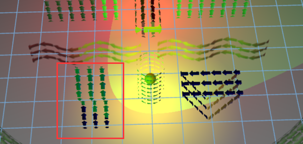
例子动图:

上面场景中主要的知识点包括:3D 灯光以及 3D 模型的流动。
- 场景搭建
整个场景中包括 2D 场景(也就是鹰眼部分)以及 3D 场景:
dm = new ht.DataModel();
g3d = new ht.graph3d.Graph3dView(dm);
g3d.setGridVisible(true);//指定是否显示网格
g3d.setGridColor('#74AADA');//指定网格线颜色
g3d.getView().className = 'main';//设置类名
document.body.appendChild(g3d.getView());//将3d组件添加进body体中
window.addEventListener('resize', function(e) {
    g3d.invalidate();
}, false);

g2d = new ht.graph.GraphView(dm);
g2d.setAutoScrollZone(-1);//设置自动滚动区域大小,当鼠标距离拓扑边缘小于这个值时,拓扑自动滚动(调整translateX或translateY)
g2d.getView().className = 'g2d';
g2d.setEditable(true);//设置拓扑中的图元是否可编辑
document.body.appendChild(g2d.getView());
ht.Default.callLater(g2d.fitContent, g2d, [true, 50, true]);//获取全局下一个id编号

g3d.setHeadlightRange(2000);//灯影响范围,默认为0代表可照射到无穷远处,如果设置了值则光照射效果随物体远离光影而衰减
所有
HT组件最根层都为一个 div 组件,可通过组件的 getView() 函数获得,这里就是利用这种方法将 3D 和 2D 组件添加进 body 体中的。只要 3D 和 2D 共用同一个数据容器,那么数据容器中的图元都是共用的,也就是说只要我们排布好 2D 或者 3D 中的图元,那么剩下的那个组件中图元的排布以及样式都是根据排布好的组件来排布的。 - 添加灯光
场景中出现的灯光,除了会旋转的灯光,还有就是两个静止的红灯和黄灯,当旋转的灯光照向其他地方的时候看得比较清楚:
redLight = new ht.Light();//灯类
redLight.p3(0, 0, -175);//实例变量的位置
redLight.s({
    'light.color': 'red',//灯光颜色
    'light.range': 400//灯影响范围,默认为0代表可照射到无穷远处,如果设置了值则光照射效果随物体远离光影而衰减
});
dm.add(redLight);//将实例变量添加进数据容量中

rotateLight = new ht.Light();
rotateLight.s({
    'light.color': 'green',
    'light.type': 'spot'//默认为point点光灯,可设置为spot聚光灯,以及directional的方向光类型
});
dm.add(rotateLight);

yellowLight = new ht.Light();
yellowLight.p3(0, 0, 60);
yellowLight.s({
    'light.color': 'yellow',
    'light.range': 200
});
dm.add(yellowLight);
- 场景中模型的构建
首先是地板的创建,地板是一个圆形的地板,通过设置样式 shape3d 为 cylinder,剩下的只要设置好大小、位置以及样式等等即可:
floor = new ht.Node();//Node 节点类
floor.s3(1100, 10, 1100);
floor.p3(0, -100, -110);
floor.s({
    'shape3d': 'cylinder',//设置 3D 模型为圆形
    'shape3d.side': 100,//默认值为0,决定3d图形显示为几边型,为0时显示为平滑的曲面效果
    'shape3d.color': 'white',//默认值为#3498DB,3d图形整体颜色
    '3d.selectable': false,//默认值为true,控制图元在Graph3dView上是否可选中
    '2d.visible': false//默认值为true,控制图元在GraphView上是否可见
});
dm.add(floor);
接着添加地板外围的 8 根圆柱:
for(var i=0; i<8; i++){
    var angle = Math.PI*2*i/8;
          pillar = new ht.Node();
    pillar.s({
        'shape3d': 'cylinder',
         'shape3d.color': 'white',
         'shape': 'circle',//多边形类型图元,为空时显示为图片
         'shape.background': 'gray'//多边形类型图元背景
    });
    pillar.s3(50, 180, 50);
    pillar.p3(Math.cos(angle)*480, 0, -110+Math.sin(angle)*480);
    dm.add(pillar);
}
还有就是这些“箭头”作为贴图的模型,各种各样的,这里我就只解析一个,比较靠前的“波动”部分,具体的多边形的描述请参考形状手册:
其中 image 的部分是通过 ht.Default.setImage 函数来创建的名为 arrow 的贴图。shape3 = new ht.Shape();//多边形类 dm.add(shape3); shape3.setTall(60);//设置高度 shape3.setThickness(0);//设置厚度 shape3.s({//设置样式 'shape.background': null, 'shape.border.width': 10,//多边形类型图元边框宽度 'shape.border.color': 'blue', 'all.visible': false,//六面是否可见 'front.visible': true, 'front.blend': 'blue',//前面染色颜色 'front.reverse.flip': true,//前面的反面是否显示正面的内容 'front.image': 'arrow',//前面贴图 'front.uv.scale': [16, 3]//前面贴图的uv缩放,格式为[3,2] }); shape3.setPoints([//设置点数组 {x: 0, y: 0}, {x: 25, y: -25}, {x: 50, y: 0}, {x: 75, y: 25}, {x: 100, y: 0}, {x: 125, y: -25}, {x: 150, y: 0}, {x: 175, y: 25}, {x: 200, y: 0} ]); shape3.setSegments([//描述点连接样式 1, // moveTo 3, // quadraticCurveTo 3, // quadraticCurveTo 3, // quadraticCurveTo 3 // quadraticCurveTo ]); shape3.p3(-100, 0, 100); shape3.setRotationZ(-Math.PI/2);//设置图元在3D拓扑中沿z轴的旋转角度(弧度制)
- 设置定时器使各个模型中的图片“流动”以及旋转灯光的旋转
offset = 0;
angle = 0;
setInterval(function(){
    angle += Math.PI/50;
    rotateLight.p3(400*Math.cos(angle), 70, -110+400*Math.sin(angle));//设置旋转灯光的坐标

    offset += 0.1;
    uvOffset = [offset, 0];
    shape1.s({
        'front.uv.offset': uvOffset//前面贴图的uv缩放,格式为[3,2]
    });
    shape2.s({
        'front.uv.offset': uvOffset
    });
    shape3.s({
        'front.uv.offset': uvOffset
    });
    shape4.s({
        'front.uv.offset': uvOffset
    });
    shape5.s({
        'shape3d.uv.offset': uvOffset,//决定3d图形整体贴图的uv缩放,格式为[3,2]
        'shape3d.top.uv.offset': uvOffset,//决定3d图形顶面贴图的uv缩放,格式为[3,2]
        'shape3d.bottom.uv.offset': uvOffset//决定3d图形底面贴图的uv缩放,格式为[3,2]
    });
    cylinder.s({
        'shape3d.uv.offset': uvOffset
    });
    torus.s({
        'shape3d.uv.offset': uvOffset
    });
}, 200);
整个例子结束,感觉就是“小代码大效果”,代码量少而且简单,效果又非常不错,大家有兴趣可以去官网或者手册中查看其它的例子。

