
RFID 仿真/模拟/监控/拦截/检测/嗅探器
Sound card based RFID sniffer/emulator
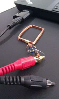
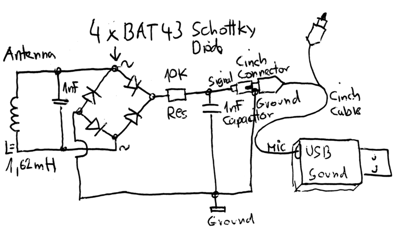
(Too tired after recon.cx to do draw the schematics better than that :) Stay tuned for the next version including Tag emulation.)
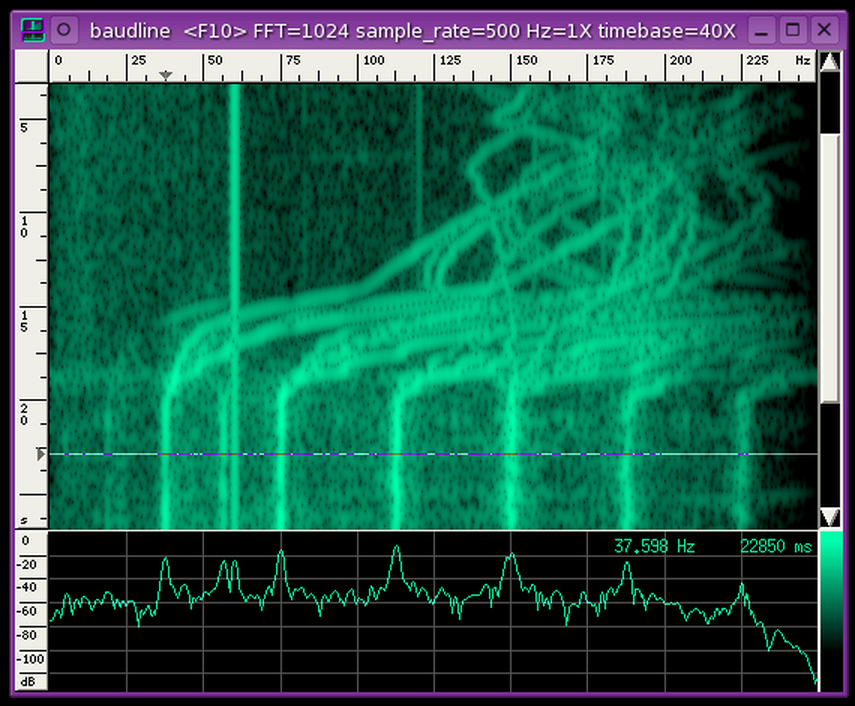
- baudline FFT signal analyzer for sniffing LF RFID tags using our sound card based RFID sniffer/emulator (more information soon!).
PicNic - yet another emulator/spyware for HF RFID

Abstract
Rather than a final construction, this is just an experimental kit addressed to anybody, who wants to play with e.g. MIFARE chip emulation etc. It has two main parts – HW module which is a simple microcontroller driven HF RFID transceiver and a particular SW module which does the particular job (fake UID sending, terminal spying, MIFARE hacking, etc.). The modules currently available in public are listed bellow. Of course, it is definitely up to you to build your own HW/SW modules basing on some of those already existing. Remember – this is a kit... it all started as a demo project for my students, then I decided to put it here - just for an inspiration.
The name PicNic itself explain the main design paradigm and also tells why I did construct „yet another emulator/spyware“. The word “Pic” comes from the name of the microcontroller family being used, while “Nic” comes from the Czech word for “Nothing”. So, PicNic = PIC and „Nothing else around it“. Thus, in opposite to the other designs available on the internet which often try to be as robust as possible, I searched for a minimal design possible. I do not say I have reached the absolute minimum, but I feel I am close enough.
The whole design is addressed to people with a moderate knowledge of radio electronics, PIC programming, and RFID technology.
Documentation
Rosa, T.: PicNic for HF RFID, Santa’s Crypto Get-together 2008, Rump Session presentation, Prague
Klima, V. and Rosa, T.: PicNic pro RFID-KV, Sdelovaci technika, 1/2009
(this article is in Czech, I hope I will find a time to translate it; nevertheless, the scheme and short notes presented bellow together with source code comments in assembler files should be enough to understand how it works and how to build it up)
HW design
Note on the PIC clock source
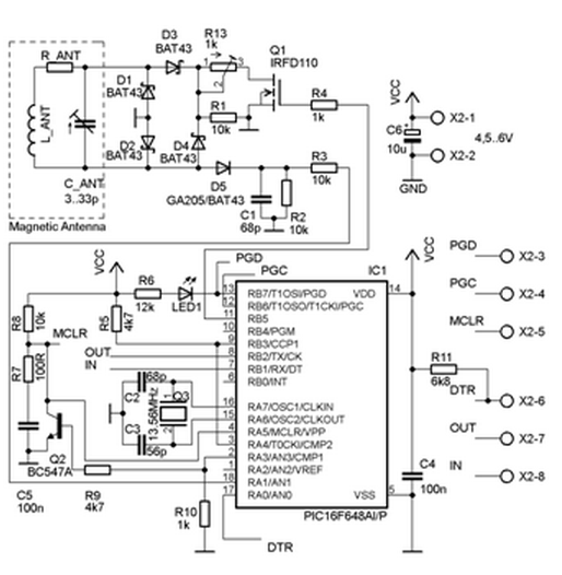
The microcontroller oscillator is driven by X-tal with parallel resonant frequency at 13.56 MHz. We should use a parallel cut with a load capacitance approx. 30 pF. Using the same frequency as of the basic carrier, we can get easily synchronized with the RFID terminal on the very basic level of the instruction flow.
Note on the magnetic antenna design
The analog part uses magnetic antenna which is dictated by the fact that HF RFID operates in the near field range where the inductive coupling is reasonable. Rather than a particular antenna type, a general design rules are presented here. The antenna is composed of the main coil, the serial resistor, and the resonant capacitor. From the electromagnetic field viewpoint, the coil should be constructed as 4 to 15 turns in a plane around a surface similar to a general ISO card. From the circuit viewpoint, the inductance should be kept at moderate level (tents of uH at maximum) as we need to set the resonant capacitor accordingly. The well known Thomson formula can be used as an estimate here:
f = 1/[2*Pi*sqrt(LC)].
Furthermore, we must care about the quality (the Q factor) of the antenna as it limits the transceiver bandwidth. Let us say we need 1.7 MHz bandwidth (as the subcarrier for ISO 14443A is 847.5 kHz), then we can use the following estimation for the serial resistance:
R > 3.4*Pi*10^6*L.
We keep the value of R_ANT as low as possible otherwise, as we do not want to mute the antenna too much.
A classical diode AM detector is coupled to the antenna directly.
Its output is then fed to the analog input RA1.
An internal comparator is working there which output is fed to TMR0 and CCP modules of PIC.
TMR0 is used to “de-modify” the modified Miller encoding used by ISO 14443A for terminal data transmission.
The CCP module is used as a capture register for TMR1 which is then used to synchronize the time frame for the emulator response
(cf. ISO 14443-3A for the detailed requirements).
Another part attached to the antenna circuit is the load modulator.
It is composed of a Graetz bridge which load impedance is driven by an induced N-channel MOSFET.
Note that using this technology over a classical bipolar transistor turned out to be necessary
due to a poor switching characteristic of the bipolar one when driven by an asymmetric input source at 847.5 kHz.
On the other hand, the gate saturation voltage affects the minimum power requirements of the whole PicNic.
If we want to go bellow 4.5 V, a different part with a lower saturation voltage should be considered.
The whole modulation impedance is mainly resistive and the resistance can be adjusted by R13 (we start at the value of 100 Ohms typically).
The MOSFET itself is driven by RB5 digital output.
Note on the external communication
The design expects an USART connection to the outside world as well. We shall not forget to do a proper signal conversion, of course.
To connect a RS232 of PC, we can use, for instance, a well known MAX232 convertor of Maxim.
We can also use the FTDI chips if we want a straight forward connection via USB.
I also have a very good experience with the Bluetooth serial adaptor OEMSPA311i of ConnectBlue.
The particular communication speed etc. is up to the particular SW module.
As the clock frequency is the same as of the basic carrier,
we can derive the (13.56*10^6/128) bps (approx. 106 kbps) or (13.56*10^6/64) bps (approx. 212 kbps) easily.
The question is, of course, what we can set on the receiver’s part.
It is worth noting that FTDI controllers are equipped with so-called rational (or sub-integer) divider
which allows quite precise setup for wide range of communication speeds. This is another reason why using the FTDI chips is quite reasonable.
The signals used for the communication are Rx, Tx, and DTR.
There is a circuit (cf. the scheme and the source code initialization) that performs automatic hard reset of the PIC on each DTR signal change.
The simple scheme works mainly because of the PORTA pins going to the high impedance state with the falling edge
on MCLR and the possibility to ex-or the comparator output with a user defined bit value.
The serial line is planned mainly for sniffing and monitoring purpose.
Details on how the particular firmware employs the serial line can be found in the particular source code comments…
Crypto1 enhancement
To support MIFARE Classic attacks on schemes relying both on UID and crypto memory access,
the version with Crypto1 coprocessor support is currently under construction.
The coprocessor itself is a (V)HDL design (many thanks to Jiri Bucek <jiri_dot_bucek (at) fit_dot_cvut_dot_cz> for his vital help and patience)
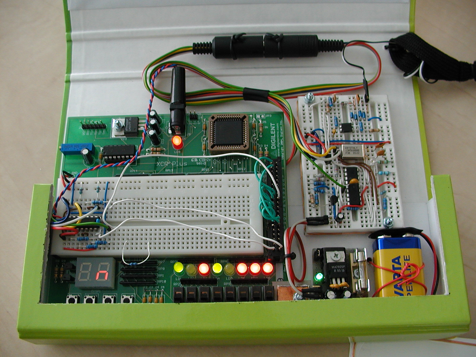
targeted for a simple CPLD devices. In particular, the (a bit obsolete)Digilent’s Digilab XCRP circuit board featuring the Xilinx XCR3064XL is used, now.
Current status of the project:
- VHDL design: OK
- VHDL testbench: OK
- PicNic interconnection: OK
- Key load procedure: OK
- UID and n_T load procedure: OK
- MIFARE Classic login procedure: OK
- MIFARE Classic simple read procedure: OK
- Access control reader protocol: sometimes fails – to be further tested
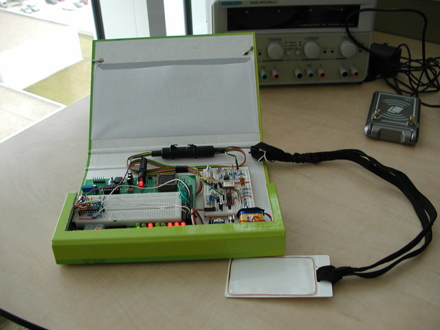
Some pictures of the whole prototype design can be found here:
device detail, inner side, outer box.
ALPHA codes snapshot - just to get an idea (interconnection with CPLD can be derived from the sources).
http://crypto.hyperlink.cz/files/FakeUIDCrypto_1_0_alpha.zip
(Ab)Using the NFC-WI/S2C interface (SAM-PicNic)
This interface is supported by several NFC front ends of NXP, mainly by the PN511 and PN512.
Note that these chips are also embedded in the PN531, PN532, and PN533 controllers,
since those devices are in fact composed of PN511 (or PN512) plus certain 80C51-based microcontroller core.
The NFC-WI/S2C interface main purpose is to allow using the core analog Tx/Rx path for attaching the so-called Secure Module (SAM).
The Secure Module can be, for instance, a somehow stripped MIFARE Classic chip (only its digital part is used).
The interface provides mainly the following five signals: power source/reference, GND, SIGOUT, SIGIN, and SIC_CLK.
The SIGOUT is an output providing modified Miller encoded data (the particular analog signal appearance depends on the particular registry configuration of the controller). The SIGIN is an input expecting Manchester coded signal with the subcarrier of 847.5 kHz (modulation signal of the transponder). The SIC_CLK provides recovered basic carrier signal of 13.56 MHz. Some other signals can be added to this interface, provided these are useful for the specific purpose. For instance, there is the CLAD signal allowing the SAM to inform the controller about start/end of the SAM RF-activity. Details can be found in the technical documentation of NXP. It can be obtained from NXP under NDA. In time of writing this notice, however, a copy of it appeared in the doc lib at www.proxmark.org.
The idea of attaching the PicNic is that simple:
- use SIGOUT in place of the antenna/demodulator output
- use SIGIN in place of MOSFET load modulator input
- use SIC_CLK as a clock source for the PIC16F648A (as it supports external clock signal allowing even the DC idle state!); yes(!)
– the choice of designing the PicNic firmware as for the PIC having the clock signal the same as the RF basic carrier finally pays off here.
The main benefits of this setup should be:
- much better timing synchronization of the PicNic Rx and Tx (mainly the Tx-after-RX frame delay)
- possibility to simply “implant” PicNic into existing NFC devices; this could allow using existing antenna and low-level analog design as well as hiding the PicNic into, for instance, an NFC equipped mobile phone etc.
Current status of the project:
- prepare a demo board for SAM-PicNic experiments: OK
It is based on SCL3710 dongle. The interesting signals of PN531 have been drawn outside the original PCB layout. Cf. overall demo board design or SCL3710 interconnection details. The SCL3710 is driven by the libnfc library via USB channel.
- research the interconnection details: to be done (basing on the demo board measurements)
- redesign PicNic fw (minor changes are expected): to be done
- verify the real PicNic implantation: to be done
SW modules
FakeUID 1.3.2 – emulator of ISO14443A anticollison handshake for 4 bytes long UID. Certain support for data gathering for MIFARE Classic cryptanalysis is also added (see comments in the source code).
FakeUID 1.4-beta – supports ISO14443A UID of all lengths (4/7/10 bytes) and presents a redesigned Tx synchronization to allow easier application protocol extension (see comments in the source code).
FakeUID 1.4 – final version, minor changes done and some bugs corrected.
FakeUID 1.5-beta – adds a better support for the DESFire emulation. Allows capturing of terminal response for the Authenticate command. This enables offline key guessing attacks. Furthermore, it adds support for the R(NAK) – R(ACK) ping-pong which is used by some readers (e.g. CardMan 5321) to check the presence of a transponder in the terminal field. The ATS support is added as well.
FakeUID 1.5-beta OpenCard Special Edition –
the exact experimental version employed for OpenCard partial emulation in applications relaying only on static transponder data (mainly UID).
Surprisingly, such applications were already found!
This firmware was used to show that building security of RFID applications on UID-only approach is really very, very bad idea.
The whole story (in Czech) is captured here. Some technical details were discussed in this lecture (CZ).
Recommended reading
[1] Finkenzeller K.: RFID Handbook, John Wiley & Sons Ltd., 2nd edition, 2004
[2] Lee, Y.: Antenna Circuit Design for RFID Applications, Microchip Tech. Inc., 2003
[3] PIC16F627A/628A/648A Data Sheet, Microchip Tech. Inc., 2007
USING AN AVR AS AN RFID TAG


Experiments in RFID, continued…
Last time, I posted an ultra-simple “from scratch” RFID reader, which uses no application-specific components: just a Propeller microcontroller and a few passive components. This time, I tried the opposite: building an RFID tag using no application-specific parts.
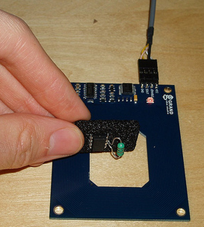
Well, my solution is full of dirty tricks, but the results aren’t half bad. I used an Atmel AVR microcontroller (the ATtiny85) and a coil. That’s it. You can optionally add a couple of capacitors to improve performance with some types of coils, but with this method it’s possible to build a working RFID tag just by soldering a small inductor to an AVR chip:
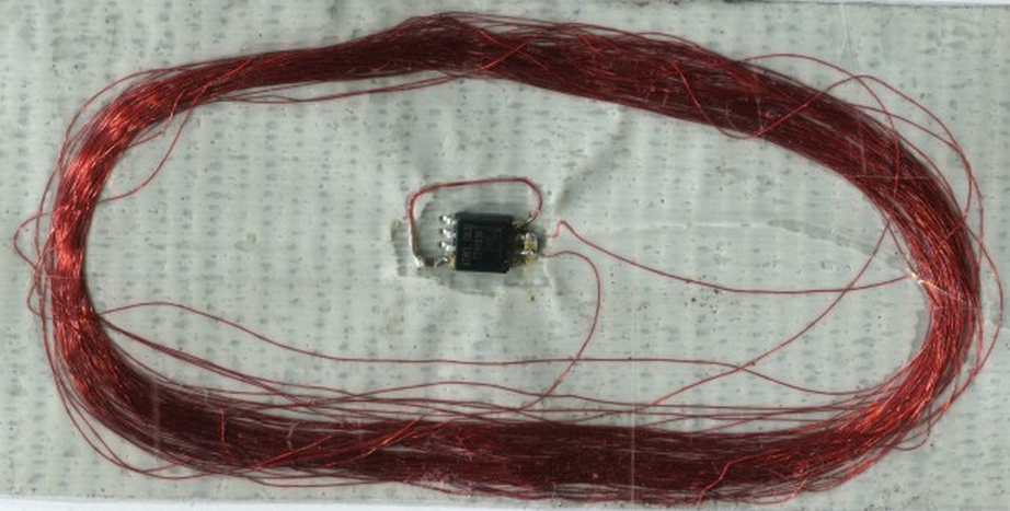
The above prototype emulates an EM4102-style tag- a very popular style of low-frequency RFID tag which stores a 40-bit unique ID. I can read my bogus ID value (0x12345678AB) using Parallax’s RFID reader. Below is another prototype, with a larger coil and a couple of capacitors for added range and stability. It is programmed to emulate a HID prox card, a simple FSK-modulated tag with a 44-bit payload. I can read this card successfully with my garage door opener. This one is a little large to conveniently carry around, but a smaller AVR package should help.
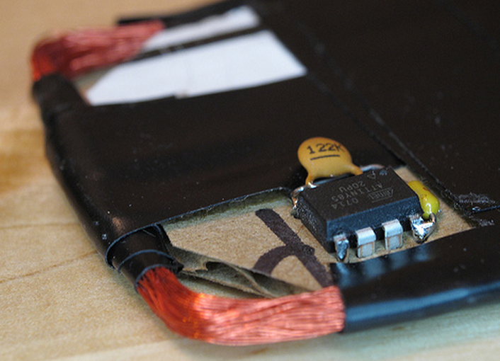
So, the shiny electrical tape is beautiful, but how does this thing even work? The power pins on the microcontroller aren’t even connected!
As I said, this makes use of several dirty tricks:
- The coil actually powers the AVR through two of its I/O pins. Nearly every chip out there has clamping diodes on its I/O pins, which prevent voltages on that pin from rising above the chip’s supply voltage or sinking below ground. These diodes are useful for arresting static discharge.When you first hold the RFID tag up to a reader, the chip has no power- the supply voltage is zero. When the coil starts to pick up power from the RFID reader, these two I/O pins are presented with a sine wave, a few volts in amplitude. Anywhere that sine wave exceeds the supply voltage, some energy is diverted from the coil to the chip’s supply rails, via the clamping diode. The end result is that the chip is powered, and the coil’s sine wave is truncated. The top and bottom of the sine have been chopped off, and it looks a lot more like a square wave now.
- Power filtering using the AVR’s die capacitance. In the smaller prototype, there is no power filtering capacitor at all. In fact, the power is filtered by the internal capacitance of the power planes in the AVR’s silicon die. This isn’t much, but it makes the power supply stable enough that we can execute code even though the supply is pulsing at 125 kHz.
- Very low voltage operation. This particular ATtiny85 chip is specified for operation at voltages as low as 2.5v. The extended voltage range version (I didn’t have any of these handy) is specified down to 1.8v. But I’m running these AVRs at barely over 1 volt. At these voltages, the normal AVR clock oscillators don’t work- but I can get away with this because of the next hack…
- The coil is the AVR’s clock source. The inductor isn’t just hooked up to any I/O pin: it’s actually connected to the AVR’s clock input. Remember the square-ish wave we’re left with after the clamping diodes suck away some power? That waveform is now our clock input. The microcontroller is executing code at 125 kHz, in lockstep with the RFID reader’s carrier wave.
- Firmware? What firmware? At such low speeds, the chip’s firmware looks less like a program, and more like a sequence of I/O operations to perform in sync with each carrier clock cycle. There aren’t a lot of cycles to spare. In the EM4102 protocol, you could potentially do some useful work with the 32 clock cycles you have between each bit. With the HID protocol, though, you need to output an FSK edge as often as once every 4 clock cycles. As a result, the firmware on the RFID tag is extremely dumb. The “source code” is really just a set of fancy assembler macros which convert an RFID tag code into a long sequence of I/O instructions.
The fact that this thing works at all is quite a testament to the robust design of the AVR. The latest AVRFID source is in Subversion, as usual.
/*
 * Software-only implementation of a passive low-frequency RFID tag,
 * using an AVR microcontroller.
 *
 * Version 1.1, 2010-06-15
 *
 * Copyright (c) 2008-2010 Micah Dowty <micah@navi.cx>
 * See end of file for license terms. (BSD style)
 * Improved HID modulation contributed by Luke Koops <luke.koops@gmail.com>
 * HID parity bit support contributed by Cesar Fernandez <cex123@gmail.com>
 *
 * Supports EM4102-style tags, and the HID 125 kHz prox card protocol.
 * The card format and ID number are set below, with #defines.
 *
 * Basic schematic:
 *
 *              ATtiny85
 *              +--------------+
 *            --| RST      Vcc |--
 *    +- L1 ----| B3/CLKI  SCK |--
 *    +---------| B4      MISO |--
 *            --| GND     MOSI |--
 *              +--------------+
 *
 * L1 is about 1 mH. It and the AVR are the only components.
 * All other pins should be unconnected.
 *
 * AVR notes:
 *
 *   - Low-voltage parts are better, but I've had success using
 *     this with the non-extended voltage range parts as well.
 *
 *   - Program the fuses for an external clock with no divider.
 *     On the ATtiny85, this means setting lfuse to 0xC0.
 *     Note that after you set this fuse, your programmer will
 *     need to supply a clock on pin 2 for subsequent programming
 *     operations.
 *
 * Optional parts:
 *
 *   - Power decoupling capacitor, between 0.1 and 10uF.
 *     Bigger is generally better, as it will increase the
 *     usable range- but if you use this tag with readers that
 *     have a pulsed carrier wave, bigger caps may take too long
 *     to charge.
 *
 *   - A load capacitor, in parallel with L1. This will depend
 *     on your coil. For physically small coils, the internal
 *     capacitance of the AVR seems to be enough. For larger coils,
 *     it may be necessary to use a cap here. Experiment to find the
 *     best value.
 *
 *   - A header, for in-circuit programming. You'll need to expose nearly
 *     every pin on the chip, since the AVR will also need an external
 *     clock.
 *
 *   - If you want to make an active (powered) tag, you could hook a 3V
 *     battery up to the Vcc and GND pins on the AVR. To decrease the power
 *     usage when idle, you may want to hook a large (a couple megohm)
 *     pull-down resistor to the clock input, to be sure CLKI doesn't float
 *     when there is no RF field present.
 *
 * Theory of operation:
 *
 *   Like all passive RFID tags, this circuit is powered by the 125 kHz
 *   carrier wave emitted by the RFID reader. In our case, the coil is
 *   just connected to two AVR I/O pins. We're actually powering the AVR
 *   through its protective clamping diodes, and the power is retained by
 *   the AVR die's internal capacitance.
 *
 *   This is a very weak power source, and the AVR typically gets little
 *   over a volt of Vcc. As a result, most of the AVR's oscillators won't
 *   start. We can, however, use the carrier wave itself as a clock as well.
 *   This also makes the software easy, since the instruction clock is also
 *   the RF clock. We're already clamping the coil voltage into something
 *   resembles a square wave, so this makes a good external clock source.
 *
 *   To send data back to the reader, passive RFID tags can selectively
 *   attenuate the reader's carrier wave. Most RFID tags do that with a
 *   transistor which shorts their coil. We accomplish this by driving the
 *   coil I/O pins to ground, by toggling the DDRB register. Since the I/O
 *   drivers on the AVR are weaker than the RF signal, we still get enough
 *   of a pulse to provide the CLKI input.
 *
 *   And that's about all there is to it. The software is quite simple- we
 *   are mostly just using assembler macros to convert the desired RFID tag
 *   code into sequences of subroutine calls which output bits. We can't
 *   get too fancy with the software, since it's only executing at 125 kHz.
 *
 */

/************ Configuration *****************************************/

// Uncomment exactly one format:

#define FORMAT_IS_EM4102
//#define FORMAT_IS_HID

// For the EM4102: An 8-bit manufacturer ID and 32-bit unique ID.

#define EM4102_MFR_ID        0x12
#define EM4102_UNIQUE_ID    0x3456789A

/*
 * For the HID card:
 *   A 20-bit manufacturer code, 8-bit site code, and 16-bit unique ID, 1-bit odd parity.
 *
 * Manufacturer code is fixed. If modified, HID readers do not recognise the tag.
 * (This may also be a kind of fixed header.) Tested on HID readers with 26-bit wiegand output.
 */

#define HID_MFG_CODE        0x01002  // Do not modify
#define HID_SITE_CODE       0x9F
#define HID_UNIQUE_ID       1326     // May be written on the back of the card

/************ Common ************************************************/

#ifndef __ASSEMBLER__
#define __ASSEMBLER__
#endif
#include <avr/io.h>

.global main

#define OUT_PINS       _BV(PINB3) | _BV(PINB4)

    .macro    delay cycles
    .if \cycles > 1
    rjmp    .+0
    delay    (\cycles - 2)
    .elseif \cycles > 0
    nop
    delay    (\cycles - 1)
    .endif
    .endm

    .macro    manchester bit, count=1
    .if        \count
    manchester (\bit >> 1), (\count - 1)
    .if        \bit & 1
    baseband_1
    baseband_0
    .else
    baseband_0
    baseband_1
    .endif
    .endif
    .endm

    .macro    stop_bit
    baseband_0
    baseband_1_last
    .endm


/************ EM4102 Implementation *********************************/

/*
 * The common EM4102 cards use Manchester encoding, at a fixed rate of
 * 64 RF clocks per bit. This means 32 clock cycles per half-bit (baseband
 * code). There are a total of 64 manchester-encoded bits per packet. 40
 * of these are payload, 9 bits are header (all ones) and one bit is a stop
 * bit (zero). All other bits are parity, with one row parity bit every
 * 4 bits, and four column parity bits at the end of the packet.
 */

#ifdef FORMAT_IS_EM4102

#define ROW_PARITY(n)  ( (((n) & 0xF) << 1) | \
                         (((n) ^ ((n) >> 1) ^ ((n) >> 2) ^ ((n) >> 3)) & 1) )

#define COLUMN_PARITY  ( (EM4102_MFR_ID >> 4) ^        \
                         (EM4102_MFR_ID) ^             \
                         (EM4102_UNIQUE_ID >> 28) ^    \
                         (EM4102_UNIQUE_ID >> 24) ^    \
                         (EM4102_UNIQUE_ID >> 20) ^    \
                         (EM4102_UNIQUE_ID >> 16) ^    \
                         (EM4102_UNIQUE_ID >> 12) ^    \
                         (EM4102_UNIQUE_ID >> 8) ^     \
                         (EM4102_UNIQUE_ID >> 4) ^     \
                         (EM4102_UNIQUE_ID) )

main:

        .macro    baseband_0
        rcall    baseband30_0
        rjmp    .+0
        .endm

        .macro    baseband_1
        rcall    baseband30_1
        rjmp    .+0
        .endm

        .macro    baseband_1_last
        rcall    baseband30_1
        rjmp    main
        .endm

        .macro    header
        manchester 0x1FF, 9
        .endm

        header
        manchester    ROW_PARITY(EM4102_MFR_ID >> 4), 5
        manchester    ROW_PARITY(EM4102_MFR_ID >> 0), 5
        manchester    ROW_PARITY(EM4102_UNIQUE_ID >> 28), 5
        manchester    ROW_PARITY(EM4102_UNIQUE_ID >> 24), 5
        manchester    ROW_PARITY(EM4102_UNIQUE_ID >> 20), 5
        manchester    ROW_PARITY(EM4102_UNIQUE_ID >> 16), 5
        manchester    ROW_PARITY(EM4102_UNIQUE_ID >> 12), 5
        manchester    ROW_PARITY(EM4102_UNIQUE_ID >> 8), 5
        manchester    ROW_PARITY(EM4102_UNIQUE_ID >> 4), 5
        manchester    ROW_PARITY(EM4102_UNIQUE_ID >> 0), 5
        manchester    COLUMN_PARITY, 4
        stop_bit

        /*
         * Emit a 0 at the baseband layer.
         * Takes a total of 30 clock cycles, including call overhead.
         */
baseband30_0:
        ldi    r16, OUT_PINS        // 1
        rjmp    baseband30        // 2

        /*
         * Emit a 1 at the baseband layer.
         * Takes a total of 30 clock cycles, including call overhead.
         */
baseband30_1:
        ldi    r16, 0            // 1
        rjmp    baseband30        // 2

        /*
         * Internal routine for baseband32_0 and _1. Must use
         * a total of 24 clock cycles. (32 - 1 ldi - 2 rjmp - 3 rcall)
         */
baseband30:
        out    _SFR_IO_ADDR(DDRB), r16        // 1
        delay    19                // 19
        ret                    // 4

#endif /* FORMAT_IS_EM4102 */


/************ HID Implementation *********************************/

/*
 * This works with the HID 125 kHz prox cards I've tested it with,
 * but there are undoubtedly other formats used by HID. My cards are
 * marked with the model number "HID 0004H".
 *
 * These cards use both manchester encoding and FSK modulation. The FSK
 * modulation represents zeroes and ones using 4 and 5 full RF cycles, respectively.
 * An entire baseband bit lasts 50 RF cycles.
 *
 * Each packet begins with a header consisting of the baseband bit pattern "000111".
 * After that, we have 45 manchester-encoded bits before the packet repeats. The
 * last bit appears to be a stop bit, always zero. The previous 20 bits encode the
 * 6-digit unique ID, which is printed on the back of the card. The other 24 bits
 * have an unknown use. They could be a site code or manufacturing code. In the cards
 * I've examined, these bits are constant.
 */

#ifdef FORMAT_IS_HID

#define ODD_PARITY(n)  ((( ((n) >> 0 ) ^ ((n) >> 1 ) ^ ((n) >> 2 ) ^ ((n) >> 3 ) ^ \
                           ((n) >> 4 ) ^ ((n) >> 5 ) ^ ((n) >> 6 ) ^ ((n) >> 7 ) ^ \
                           ((n) >> 8 ) ^ ((n) >> 9 ) ^ ((n) >> 10) ^ ((n) >> 11) ^ \
                           ((n) >> 12) ^ ((n) >> 13) ^ ((n) >> 14) ^ ((n) >> 15) ^ \
                           ((n) >> 16) ^ ((n) >> 17) ^ ((n) >> 18) ^ ((n) >> 19) ^ \
                           ((n) >> 20) ^ ((n) >> 21) ^ ((n) >> 22) ^ ((n) >> 23) ^ \
                           ((n) >> 24) ^ ((n) >> 25) ^ ((n) >> 26) ^ ((n) >> 27) ^ \
                           ((n) >> 28) ^ ((n) >> 29) ^ ((n) >> 30) ^ ((n) >> 31) ) & 1) ^ 1)
main:
        eor    r16, r16
        ldi    r17, OUT_PINS
loop:

        /*
         * Toggle the output modulation, in the specified number
         * of total clock cycles.
         */
        .macro toggle clocks
        delay    (\clocks - 2)
        eor    r16, r17
        out    _SFR_IO_ADDR(DDRB), r16
        .endm

        /*
         * Emit a 0 at the baseband layer. (Toggle every 4 cycles, for 50 cycles)
     * There was an rjmp that got us to the beginning of the loop, so drop
     * 2 cycles from the delay if this is the first bit.  That will give the
     * appropriate delay before the toggle.
     *
     * From observing the HID card, each 0 bit is either 48 or 52 cycles.
     * The length alternates to keep the average at 50.  This keeps the
     * waveform smooth, and keeps each bit in its 50 cycle time slot.
     *
         * We don't have time for a function call, so we just chew
         * up lots of flash...
         */
        .macro    baseband_0
    .if startloop
    toggle    2        // 4
    .equ startloop, 0
    .else
        toggle    4        // 4
    .endif
        toggle    4        // 8
        toggle    4        // 12
        toggle    4        // 16
        toggle    4        // 20
        toggle    4        // 24
        toggle    4        // 28
        toggle    4        // 32
        toggle    4        // 36
        toggle    4        // 40
        toggle    4        // 44
        toggle    4        // 48
    .if evenzero
    .equ evenzero, 0
    .else
    toggle    4        // 52
    .equ evenzero, 1
    .endif
        .endm

        /*
         * Emit a 1 at the baseband layer. (Toggle every 5 cycles, for 50 cycles)
         */
        .macro    baseband_1
    .if startloop
    toggle    3        // 4
    .equ startloop, 0
    .else
        toggle    5        // 4
    .endif
        toggle    5        // 10
        toggle    5        // 15
        toggle    5        // 20
        toggle    5        // 25
        toggle    5        // 30
        toggle    5        // 35
        toggle    5        // 40
        toggle    5        // 45
        toggle    5        // 50
        .endm

        .macro header
    .equ evenzero, 0
    .equ startloop, 1
        baseband_0
        baseband_0
        baseband_0
        baseband_1
        baseband_1
        baseband_1
        .endm


    /*
     * This should add up to 45 bits.
     *
     * Some cards may use different 45-bit codes: For example,
     * a Wiegand code, or something more site-specific. But the
     * cards that I've seen use a 20-bit manufacturer code,
     * 8-bit site code, 16-bit unique ID, and a single parity bit.
     *
     * If your card uses ad ifferent coding scheme, you can add,
     * remove, and modify these 'manchester' macros. Just make sure
     * the result adds up to the right number of bits.
     */
        header
        manchester    HID_MFG_CODE, 20
    manchester    HID_SITE_CODE, 8
    manchester    HID_UNIQUE_ID, 16
    manchester    ODD_PARITY(HID_MFG_CODE ^ HID_SITE_CODE ^ HID_UNIQUE_ID), 1

        rjmp    loop


#endif /* FORMAT_IS_HID */

/*****************************************************************/

/*
 * Permission is hereby granted, free of charge, to any person
 * obtaining a copy of this software and associated documentation
 * files (the "Software"), to deal in the Software without
 * restriction, including without limitation the rights to use,
 * copy, modify, merge, publish, distribute, sublicense, and/or sell
 * copies of the Software, and to permit persons to whom the
 * Software is furnished to do so, subject to the following
 * conditions:
 *
 * The above copyright notice and this permission notice shall be
 * included in all copies or substantial portions of the Software.
 *
 * THE SOFTWARE IS PROVIDED "AS IS", WITHOUT WARRANTY OF ANY KIND,
 * EXPRESS OR IMPLIED, INCLUDING BUT NOT LIMITED TO THE WARRANTIES
 * OF MERCHANTABILITY, FITNESS FOR A PARTICULAR PURPOSE AND
 * NONINFRINGEMENT. IN NO EVENT SHALL THE AUTHORS OR COPYRIGHT
 * HOLDERS BE LIABLE FOR ANY CLAIM, DAMAGES OR OTHER LIABILITY,
 * WHETHER IN AN ACTION OF CONTRACT, TORT OR OTHERWISE, ARISING
 * FROM, OUT OF OR IN CONNECTION WITH THE SOFTWARE OR THE USE OR
 * OTHER DEALINGS IN THE SOFTWARE.
 */
AVR RFID, OPTIMIZED AND PORTED TO C
Way back in 2008, I posted a writeup about using an AVR microcontroller as an RFID tag. Since then, it’s been great to see many people pick up this code and build their own DIY RFID tags.
In my original project, I was just interested in using an AVR as a way of emulating any tag protocol I wanted, even proprietary protocols like the HID cards that are so common for door entry. But a general purpose microcontroller really lends itself to making even more interesting tags. For example, imagine an action figure that has different poses which trigger microswitches that can be read by the AVR. It could report a different RFID code depending on which pose the action figure is in. This kind of very low-power physical computing is really interesting to me.
Trammell Hudson recently took a big step in this direction, in the name of creating a “multipass” card which could stay in his pocket and pretend to be any number of other cards. His original idea didn’t quite work out, due to limitations in the HID readers. But along the way, he created an optimized version of the AVRFID firmware which uses much less flash memory, and he ported it to C so that it can be more easily extended and modified.
He made this posible by very carefully choosing the instructions in the inner loops, creating a state machine that just barely fits within the available clock cycles:
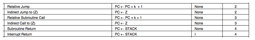
One issue with programming HID Prox compatible cards is that the AVR’s RCALL and RET instructions are quite slow — 3 and 4 clocks respectively — so making a function call and returning from it requires seven clocks and would cause errors in the RF waveform. To get around this, Beth expanded all of the code inline to produce a single function that bit-bangs the coil loading with NOP‘s between each cycle. The 20-bit manufacturer ID (0x01002), 8-bit faciity code and 16-bit unique ID, all Manchester encoded, required 80 instructions per bit for a total of 3700 instructions out of the Tiny85′s maximum of 4096. Supporting 34-bit cards would not be possible with this design, much less multiple card IDs!
While RCALL/RET are out of the question, I noticed that IJMP is only 2 clocks. This means that the CPU can do an indirect jump to the value in the 16-bit Z register in enough time to be ready for the next FSK cycle. If we know where to go, that is… The LPM instruction takes three cycles to read a byte from flash into a register, which just barely fits during the idle time during a FSK baseband one. Loading the Z register for LPM takes at least two clocks (since it is really the two 8-bit registers r31:r30), which means the pgm_read_word() macro in avr/progmem.h won’t work. While the rest of the firmware is in mostly normal C, I resorted to writing assembly to interleave the coil toggling with the operations to determine the next output state and make the appropriate jump. If you want to follow along, the source for the RFID firmware is available in rfid/avrfid2.c.
His post covers a lot of ground, including how to connect an off-the-shelf HID card reader to a computer, and how to repeatedly program the AVR using a Bus Pirate.
Go check out the full article already!
/** \file
 * AVR RFID card.
 *
 * Based on avrfrid.S by Beth at Scanlime.
 * http://scanlime.org/2008/09/using-an-avr-as-an-rfid-tag/
 *
 * Normal C code doesn't really work here since we are limited to
 * very small number of cycles per bit.  The HID Prox cards are
 * FSK modulated with only four or five RF cycles per baseband cycle.
 * Since the AVR RCALL and RET instructions take four clocks each
 * we would miss all of our timing constaints if we tried to make those calls.
 *
 * However, the IJMP only takes 2 clock cycles, so we can build a state
 * machine and use it to make "function calls".  LPM also takes three
 * clocks, so we can't load a full address and jump to it within the
 * timing constraint, but we can split these operations across the
 * ten 5-cycle transitions during sending a baseband 1.
 *
 * Each of these transitions takes 2 cycles for the XOR and OUT to
 * set the state, which leaves three cycles for our work.
 *
 * when programming with buspirate (wire/clip):
 *
 *    White/white   Reset 1  v  8 Vcc   Red
 *    Blue/Blue     Xtal1 2     7 SCK   Purple/green
 *                  Xtal2 3     6 MISO  Black/Black
 *    Black         Gnd   4     5 MOSI  Gray/Yellow
 *
 */
#include <avr/io.h>
#include <avr/pgmspace.h>
#include <avr/sfr_defs.h>

static void manchester_0(void);
static void manchester_1(void);
static void hid_header(void);
static void hid_reset(void);
//int main(void);

#define HID_MFG_CODE        0x01002  // Do not modify
#define HID_SITE_CODE       42
#define HID_UNIQUE_ID       23946     // May be written on the back of the card

#define HID_HEADER "2"
#define HID_RESET "3"

static const char hid_bits[]
PROGMEM __attribute__((__used__)) = {
#if 1
    HID_HEADER
    "0000"
    "0001"
    "0000"
    "0000"
    "0010" // HID Manufacturer code 0x01002 for n1002 cards?
    "00101010" // Site code 42
    "01011101"
    "10001010" // ID 23946
    "0" // parity
#else
    HID_HEADER
    "0001"
    "0000"
    "0000"
    "0000"
    "0010" // HID Manufacturer code, trying 10002 for 34-bit?
    "00000000" // fc-12
    "00001100"
    "00111000" // id 14371
    "00100011"
    "0"
#endif
    HID_RESET
};

typedef void (*state_function)(void);

static const state_function state_handlers[]
PROGMEM __attribute__((__used__)) = {
    manchester_0,
    manchester_1,
    hid_header,
    hid_reset,
};


#if 0
// HID manufacturer code (20 bits) == 0x01002
_0, _0, _0, _0,
_0, _0, _0, _1, _0, _0, _0, _0,
_0, _0, _0, _0, _0, _0, _1, _0,

// Facility code (8 bits) == 42
_0, _0, _1, _0, _1, _0, _1, _0,

// ID (16 bits) == 23946
_0, _1, _0, _1, _1, _1, _0, _1,
_1, _0, _0, _0, _1, _0, _1, _0,

// Parity
_0,

// And return to the header when we're done
hid_header
};
#endif


/** Use r16 and r17 to track the state of the pins.
 *
 * These are hard coded in toggle_raw().
 */
volatile register uint8_t r16 __asm__("r16");
volatile register uint8_t r17 __asm__("r17");

/** r15 tracks which bit are we currently sending.
 *
 * This is hard coded in hid_header().
 */
volatile register uint8_t bit_num __asm__("r15");


/** Jump to what ever has been stored into Z (r31:r30)
 *
 * PC <- Z
 * 2 clocks
 */
static inline void
__attribute__((__noreturn__))
ijmp(void)
{
    __asm__ __volatile__("ijmp");
    while(1); // make gcc happy
}


/**
 * Delay a specific number of clock cycles.
 *
 * rjmp is 2 clocks, nop is 1.
 *
 * So do one nop if the delay is an odd value and then rjmp's for n/2
 * to maximize code density.  Doesn't matter for the state machine version,
 * but otherwise the straight-code version would overflow the 8 KB space.
 */
static inline void
__attribute__((__always_inline__))
delay(
    const uint8_t n
)
{
    switch (n/2)
    {
    case 8: asm("rjmp .+0");
    case 7: asm("rjmp .+0");
    case 6: asm("rjmp .+0");
    case 5: asm("rjmp .+0");
    case 4: asm("rjmp .+0");
    case 3: asm("rjmp .+0");
    case 2: asm("rjmp .+0");
    case 1: asm("rjmp .+0");
    case 0: break;
    }

    if (n % 2 == 1)
        asm("nop");
}


/** Toggle the output pins to change the coil state.
 *
 * The DDRB pins are used to short the coil, which causes
 * an increase in current draw at the reader.
 *
 * 2 clocks.
 */
asm(
    ".macro toggle\n"
    "eor r16, r17\n"
    "out 0x17, r16\n" // _SFR_IO_ADDR(DDRB)
    ".endm\n"
);


static void
__attribute__((__always_inline__))
toggle_raw(void)
{
    __asm__ __volatile__("toggle");
}


/** Toggle the state of the output pins and delay for some clocks.
 *
 * The toggle_raw() takes 2 clocks, so we delay for the remainder.
 */
static void
__attribute__((__always_inline__))
toggle(
    const uint8_t n
)
{
    toggle_raw();

    if (n > 2)
        delay(n-2);
}

#define ZERO_FREQ    4
#define ONE_FREQ    5


/** Send a 0 at the baseband layer.
 *
 * If delay_slot is set, the delays after the last FSK slot will not be
 * done, instead allowing the caller to make use of three extra clock
 * cycles for their own usage.
 */
static void
__attribute__((__always_inline__))
baseband_0(
    uint8_t delay_slot
)
{
    toggle(ZERO_FREQ); // 4
    toggle(ZERO_FREQ); // 8
    toggle(ZERO_FREQ); // 12
    toggle(ZERO_FREQ); // 16
    toggle(ZERO_FREQ); // 20
    toggle(ZERO_FREQ); // 24
    toggle(ZERO_FREQ); // 28
    toggle(ZERO_FREQ); // 32
    toggle(ZERO_FREQ); // 36
    toggle(ZERO_FREQ); // 40
    toggle(ZERO_FREQ); // 44
    toggle(delay_slot ? ZERO_FREQ : 0); // 48
}


/** Send a 1 at the baseband layer.
 *
 * This is only used by the header during setup since it must send
 * several 1 bits in a row.  Only the last one computes the next state.
 * There are no delay slots following this function.
 */
static void
__attribute__((__always_inline__))
baseband_1(void)
{
    toggle(ONE_FREQ); //  5
    toggle(ONE_FREQ); // 10
    toggle(ONE_FREQ); // 15
    toggle(ONE_FREQ); // 20
    toggle(ONE_FREQ); // 25
    toggle(ONE_FREQ); // 30
    toggle(ONE_FREQ); // 35
    toggle(ONE_FREQ); // 40
    toggle(ONE_FREQ); // 45
    toggle(ONE_FREQ); // 50
}


/** Send a 1 at the baseband layer.
 *
 * Interleaved with the FSK are the operations to load the next
 * function pointer.  Once the function "returns", the Z register
 * will contain the address of the next function in the state machine.
 *
 * This was too difficult to write in C and have gcc output the correct
 * stream of instructions.  Instead it is in inline assembly.
 * The rough translation into C:
 *
 *    toggle 5
 *            z = &hid_bits[bit_num];
 *    toggle 10
 *            next_state = lpm(z);
 *    toggle 15
 *            next_state = (next_state - '0') * 2
 *    toggle 20
 *            z = &state_handlers[next_state];
 *    toggle 25
 *            next_func_lo = lpm(z++);
 *    toggle 30
 *            next_func_hi = lpm(z++);
 *    toggle 35
 *            z = next_func_hi << 8 | next_func_lo;
 *    toggle 40
 *            bit_num++;
 *    toggle 45
 *            delay
 *    toggle 50
 *            No delay (leave these free for caller)
 */
static void
__attribute__((__always_inline__))
baseband_1_load(void)
{
    __asm__ __volatile__(
        "toggle /* 5 */\n"
                    "ldi r30, lo8(hid_bits)\n"
                    "ldi r31, hi8(hid_bits)\n"
                    "add r30, %0\n"
        "toggle /* 10 */\n"
                    "lpm r24, Z\n"
        "toggle /* 15 */\n"
                    "ldi r30, lo8(state_handlers)\n"
                    "ldi r31, hi8(state_handlers)\n"
                    "nop\n"
        "toggle /* 20 */\n"
                    "subi r24, '0'\n"
                    "lsl r24\n"
                    "add r30, r24\n"
        "toggle /* 25 */\n"
                    "lpm r24, Z+\n"
        "toggle /* 30 */\n"
                    "lpm r31, Z\n"
        "toggle /* 35 */\n"
                    "mov r30, r24\n"
                    "rjmp .+0\n"
        "toggle /* 40 */\n"
                    "inc %0\n"
                    "rjmp .+0\n"
        "toggle /* 45 */\n"
                    "nop\n"
                    "rjmp .+0\n"
        "toggle /* 50 */\n"
                    "/* Leave slot free */\n"
        : "=r" (bit_num) // 0
    );
}


/** Send the HID header start bits.
 *
 * The HID header is an illegal state in the Manchester encoding
 * used to indicate the start of the packet.
 *
 * The last baseband 1 will load the first state machine function
 * pointer and jump into the statemachine.
 */
static void
hid_header(void)
{

    baseband_0(1);
    baseband_0(1);
    baseband_0(1);
    baseband_1();
    baseband_1();
    baseband_1_load();
                delay(1);
                ijmp();
}


/** Output a manchester 0.
 *
 * Output a baseband 0, followed by a baseband 1.
 * During the baseband 1 the Z register will be updated
 * to contain the pointer to the next function in the state machine.
 *
 * After the 1, with one delay slot since ijmp() takes two clocks,
 * we jump to the next state.
 */
static void
manchester_0(void)
{
    baseband_0(1);
    baseband_1_load();
                delay(1);
                ijmp();
}


/** Output a manchester 1.
 *
 * Output a baseband 1, followed by a baseband 0.
 * During the baseband 1 the Z register will be updated
 * to contain the pointer to the next function in the state machine.
 *
 * After the 0, with no delay slots since ijmp() takes two clocks,
 * we jump to the next state.
 */
static void
manchester_1(void)
{
    baseband_1_load();
                delay(3); // 3 delays slots remain
    baseband_0(0);
                ijmp();
}


/** Restart the state machine at state 0.
 *
 * This must be the last state in the machine and is the first one
 * called from main to kick things off.
 */
static void
hid_reset(void)
{
    // We will start in state 0, so the next to read is 1
    // gcc keeps optimizign writes to r15 out for some reason
    __asm__ __volatile__(
        "eor %0, %0\n"
        "inc %0\n"
        : "=r"(bit_num)
    );

    __asm__ __volatile__("rjmp hid_header");
}


/** Entry point at 0x0.
 *
 * Since we linking with -nostdlib, main needs to be at 0x0.
 * The easiest way to force that with the default linker script
 * is to put it in the .vectors text section.
 */
int
__attribute__((section(".vectors")))
main(void)
{
    r16 = 0;
    r17 = _BV(PINB3) | _BV(PINB4);

    hid_reset();

    /* Never returns */
}
AVR RFID Multipass

I was inspired by Beth’s avrfid.S project to try to build a replacement for the multiple HID Prox cards that I carry for work.
Her design is simultaneously a technical tour-de-force and an example of how badly we can abuse the Atmel chips.
Here is the entire schematic:

There is no connection to power and ground: the chip is powered through leakage current from the input pins. The AC waveform is fed directly into the pins: the internal protection diodes rectify it. During negative parts of the wave the silicon die’s inherent capacitance maintains state. The CPU clock is driven by the AC as well and depends on the ability of the coil to drive more current than the chip when DDRB is configured to pull the pins to the same potential. It’s truly amazing that this works at all.
The firmware she wrote in macro assembler is easy to understand and straightfoward, but filled the entire 8 KB flash on the ATTiny85 when compiled for HID Prox cards.
Unlike the CW modulated EM41xx cards that just load the coil for thirty RF cycles to send a baseband one and don’t load the coil to send a baseband zero, the HID cards use Frequency Shift Keying (FSK) modulation.
In FSK a baseband zero is sent by cycling the load on the coil for 50 cycles at a frequency of 4 RF cycles, and a baseband one is sent by cycling the load every 5 RF cycles. Beth’s code loads the coil by setting the two bits in DDRB to 1 while holding PORTB at 0, which places a short across the coil by putting both ends at the same potential.
While it turns out that my dream of automatically selecting the right RFID card doesn’t work, read on for details of how to build your own HID compatible RFID devices and some overview of the hand-tuned assembly necessary to fit the RFID timing.
Instruction timing
One issue with programming HID Prox compatible cards is that the AVR’s RCALL and RET instructions are quite slow — 3 and 4 clocks respectively — so making a function call and returning from it requires seven clocks and would cause errors in the RF waveform. To get around this, Beth expanded all of the code inline to produce a single function that bit-bangs the coil loading with NOP‘s between each cycle. The 20-bit manufacturer ID (0x01002), 8-bit faciity code and 16-bit unique ID, all Manchester encoded, required 80 instructions per bit for a total of 3700 instructions out of the Tiny85’s maximum of 4096. Supporting 34-bit cards would not be possible with this design, much less multiple card IDs!
While RCALL/RET are out of the question, I noticed that IJMP is only 2 clocks. This means that the CPU can do an indirect jump to the value in the 16-bit Z register in enough time to be ready for the next FSK cycle. If we know where to go, that is… The LPM instruction takes three cycles to read a byte from flash into a register, which just barely fits during the idle time during a FSK baseband one. Loading the Z register for LPM takes at least two clocks (since it is really the two 8-bit registers r31:r30), which means the pgm_read_word() macro inavr/progmem.h won’t work. While the rest of the firmware is in mostly normal C, I resorted to writing assembly to interleave the coil toggling with the operations to determine the next output state and make the appropriate jump. If you want to follow along, the source for the RFID firmware is available in rfid/avrfid2.c.
The state machine
The card IDs are stored in a flash memory character array where the ASCII characters encode the states. 2 is the state that sends the HID header, state 3 is to jump back to the start, and states 0 and 1 send a zero or one. For one of my test cards, the array definition looks like this (with __used__ to indicate to gcc that this array must be present, even if it does not see any usage of it):
static const char hid_bits[]
PROGMEM __attribute__((__used__)) =
{
        "2"                    // HID_HEADER
        "00000001000000000010" // HID code 0x01002 for n1002 cards?
        "00101010"             // Site code 42
        "0101110110001010"     // ID 23946
        "0"                    // parity (should be a separate state)
    "3"                    // HID_RESET
};
The code to send a baseband one looks roughly like this, with the FSK generation interleaved with reading the next state from the hid_bits[] array and then looking up the function to call from the state_handlers[]. At the end of the function, the Z register holds the function pointer to be called next. The toggle macro takes two clocks and turns the load on the coil if it is currently unloaded, or turns it off if it is currently on. This leaves three clocks to do before the next toggle. Most of the instructions are single cycle, except for LPM which is three clocks, and RJMP .+0 which is a two clock NOP.
baseband1:
    toggle /* 5 */
                ldi r30, lo8(hid_bits)
                ldi r31, hi8(hid_bits)
                add r30, r15 // bit_num
    toggle /* 10 */
                lpm r24, Z // next_bit = lpm(hid_bits[bitnum])
    toggle /* 15 */
                ldi r30, lo8(state_handlers)
                ldi r31, hi8(state_handlers)
                nop
    toggle /* 20 */
                subi r24, '0'
                lsl r24
                add r30, r24 // z = &state_handlers[next_bit - '0']
    toggle /* 25 */
                lpm r24, Z+
    toggle /* 30 */
                lpm r31, Z
    toggle /* 35 */
                mov r30, r24 // z = lpm(z);
                rjmp .+0
    toggle /* 40 */
                inc r15 // bit_num++
                rjmp .+0
    toggle /* 45 */
                nop // Nothing to do!
                rjmp .+0
    toggle /* 50 */
                /* Leave last delay slot free */
Last year we wrote about building HID Proxcard RFID tags with attiny85 microcontrollers (based on Micah’s avrfid.s code). The C version only supported classic 26-bit cards, but I recently needed to support the “secure” HID Corporate 1000 35-bit format.
Based on Daniel Smith’s writeup on the format and some digging around, I figured out that the MFG_CODE for this format is 10-bits long with the value 0x005. He also pointed out that the 26-bit firmware had the wrong code — it is not the 20-bit code 0x01002, but is instead the 19-bit code 0x0801 and the bottom bit is part of the parity computation for the card id. If you’re using a HID branded Proxcard reader, the value that it outputs is the entire data portion, including all of the parity bits, but does not include the MFC_CODE part. If anyone knows of a table of these codes, please let me know!
I’ve updated my firmware with these changes and it works great. Emulating a 35-bit card takes 846 bytes of flash (nine more than the 26-bit cards since the state machine stores one bit per byte), so it might be possible to port this to the attiny10. I’ve also found that the tags work much better with a small capacitor across the two clock pins, as shown in the above photo.
AVRFID 1.1 FIRMWARE
I don’t normally write bloggy posts on every version of every source file I check in, but every so often an older project sees some more activity, and I love the opportunity to revisit software I wrote years ago. Sometimes I wonder why I wrote such-and-such thing that way and oh my god what an ugly hack. But usually it’s just refreshing to think about a problem I haven’t thought about in a while.
The AVRFID was a quick but rather unique project, back from when I was on a bit of a 125 kHz RFID binge culminating in the design, construction, and installation of a proxcard reader for my garage door. While I was fidgeting around with such things, it occurred to me that you could (using a whole host of dirty tricks) convince a general-purpose 8-bit microcontroller like the AVR to function as a passive RFID tag.
Since then, I received a couple patches:
- Luke Koops improved the FSK modulation for HID tags, so that the resulting waveform is much more regular.
- Cesar Fernandez described the HID card format in more detail, and implemented a parity calculation. The 45-bit code is actually composed of four distinct fields:
- A 20-bit manufacturer code or header, constant for all HID cards.
- An 8-bit site code, unique to the particular security installation.
- A 16-bit unique ID. These are often printed in decimal on the back of the card, and they seem roughly sequential.
- An odd parity bit, covering the other 44 bits.
I didn’t have my RFID gear handy, so Cesar was kind enough to verify it with his official HID reader. So I stamped a new version number on it. If you’re interested in building your own HID card emulator, there is now a much better chance it will actually work with your reader
- Grab the latest source code from Subversion.
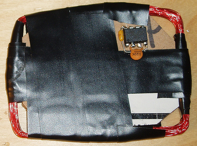
DUCT TAPE RFID TAG #1
This is just a messy first prototype, but I recently tried making an AVRFID tag on a substrate of duct tape. The first attempt involved:
- An upside-down strip of duct tape, as the base for everything else to stick atop
- 100 turns of AWG 40 magnet wire around a ~66mm diameter form, which I then haphazardly squished against the tape
- An ATtiny85 µC in the SOIC-8 package, programmed with the latest AVRFID firmware
- SMT 0.1 µF capacitor across the power pins
- SMT 1 nF capacitor in parallel with the coil, for tuning it to approximately 125 kHz
- Sealed with clear packing tape on the opposite side
It’s ugly, and I really want to try this experiment over again with a smaller IC package, like TSSOP-8. But the card works very well, and the read range is practically indistinguishable from a mass-produced RFID card. I tested this one using an official HID ProxPoint reader.
I’ve been busy, but once I have time to perfect this technique I’m hoping to write some instructions, as it’s a pretty quick and easy way to make a DIY RFID tag that’s actually in a convenient form-factor.
Stupid Simple Arduino LF RFID Tag Spoofer
UPDATE: Here is a link to an Arduino Mini shield based on these instructions
*Some enamel coated solid core copper wire (I used the green spool from the 3 spool set Radio Shack carries).
*A NPN transistor, I used a 2N3904
*A 10 K Ohm Resistor
*A 10 nF capacitor (0.01 uF). I'm using a Metalized polyester film cap I got from Radio Shack, others should work though
*A toilet paper roll to wind the wire on
I tested my circuit using a Parallax RFID serial reader connected to a second Arduino
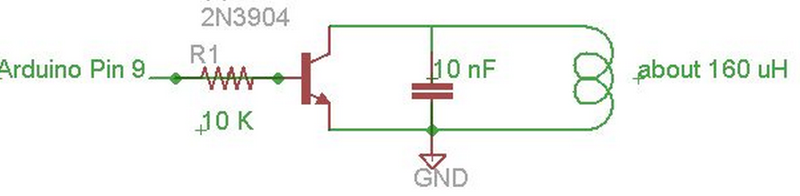
After you have your coil you can connect it to your circuit. The schematic is pretty easy. Just connect pin 9 on the Arudino to a 10 K Ohm resistor, then to the base of the transistor. Next you can put your capacitor between the collector and emitter of the transistor. The emitter also needs to be connected to ground. Next connect the coil the the emitter and collector of the transistor.
The serial number of a tag is sent over using a fairly simple protocol.
It starts by sending 9 one's
Then it sends 10 sets of 4 bits, then one parity bit (it's using even parity)
Then it sends "column" parity bits (even parity of the rows in the previous step)
Last it sends a 0 stop bit
So an example looks like this:
(start bits)
111111111
(10 rows of data - the card serial number)
(the first 4 bits are the data, the last is the even parity bit)
11110
10100
10001
11000
10010
11101
11110
00000
00011
01010
(then it sends the column parity bits, even parity of the rows above)
1101
(last a 0 stop bit)
0
See the pdf in the first link in the references section for more details on this
Image provided by Flickr user at www.flickr.com/photos/kurtisscaletta/2473469841/
//Pin to connect to the circuit
//Setting the pin LOW will tune the coil
//meaning it will respond as a high signal to the reader
//Setting the pin to HIGH will detune coil
//meaning the reader will see it as a low signal
int coil_pin = 9;

void setup( )
{
  //Set pin as output
  pinMode( coil_pin, OUTPUT );

  //Start it as low
  digitalWrite( coil_pin, LOW );
}

//Does manchester encoding for signal and sets pins.
//Needs clock and signal to do encoding
void set_pin_manchester( int clock_half, int signal )
{
  //manchester encoding is xoring the clock with the signal
  int man_encoded = clock_half ^ signal;

  //if it's 1, set the pin LOW (this will tune the antenna and the reader sees this as a high signal)
  //if it's 0, set the pin to HIGH  (this will detune the antenna and the reader sees this as a low signal)
  if ( man_encoded == 1 )
  {
    digitalWrite( coil_pin, LOW );
  }
  else
  {
    digitalWrite( coil_pin, HIGH );
  }
}

void loop( )
{
  //this is the card data we're spoofing.  It's basically 10 hex F's
  int data_to_spoof[ 64 ] =
  { 1, 1, 1, 1, 1, 1, 1, 1, 1, 1, 1, 1, 1, 0, 1, 1, 1, 1, 0, 1, 1, 1, 1, 0, 1,
    1, 1, 1, 0, 1, 1, 1, 1, 0, 1, 1, 1, 1, 0, 1, 1, 1, 1, 0, 1, 1, 1, 1, 0, 1,
    1, 1, 1, 0, 1, 1, 1, 1, 0, 0, 0, 0, 0, 0 };
  for ( int i = 0; i < 64; i++ )
  {
    set_pin_manchester( 0, data_to_spoof[ i ] );
    delayMicroseconds( 256 );

    set_pin_manchester( 1, data_to_spoof[ i ] );
    delayMicroseconds( 256 );
  }
}
RFID Spoofer
Overview
The goal of this project is to learn about RF and RFID.
Thanks to sketchsk3tch for good information.
Being new to electronics development this site was very helpful.
In short we have limited knowledge of electronics and wanted to start learning.
We thought an RFID spoofer would be a fun project.
As we learned more moving forward we decided to turn this into a dev platform for transmitting RFID and not just spoofing.
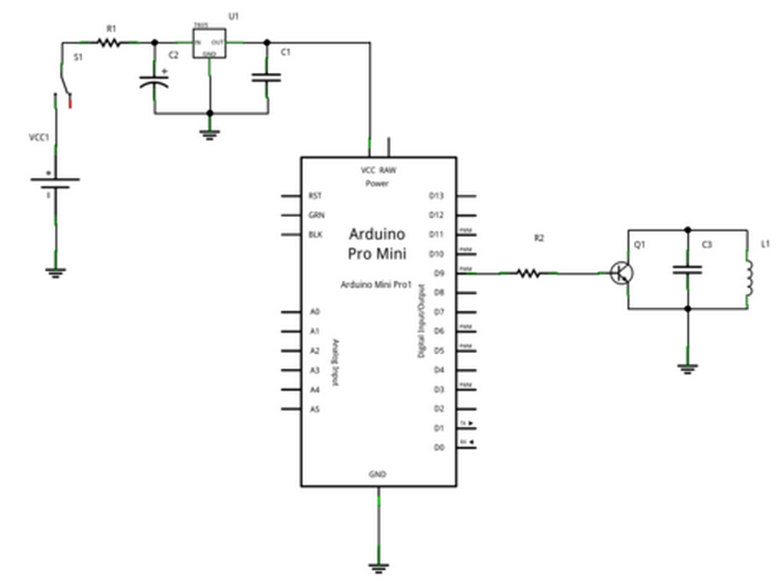
Essentially we took sketchsk3tch's project and made a shield out of it for the Arduino pro mini making it portable.
Parts List
Hardware
Antenna
-
We thought this was a good idea until we did more research. Live and learn.
-
1 x 16”x3/4” PVC pipe
-
2 x 3/4” PVC caps
-
1 x roll of 22 gauge insulated magnet wire
-
1 x male/male headphone cable (I know there is another name for this. I'll update it once I have it)
-
2 x headphone jacks
-
OR —
-
Quick and dirty to test your circuit. Better idea than the above while waiting for your coil craft inductor.
Reference http://www.instructables.com/id/Stupid-Simple-Arduino-LF-RFID-Tag-Spoofer/ -
1 x Toilet Paper Roll
-
1 x roll of 22 gauge insulated magnet wire
-
OR —
-
1 x 4312RV-905XGLB coil from http://www.coilcraft.com
PCB layout - If you want to make your own PCB. Check out our DIY PCB page.
Components
-
Arduino Pro Mini
-
SparkFun FTDI adapter to program the Pro Mini
-
VCC1 9v battery
-
S1 SPDT switch
-
R1 10 ohm resistor
-
R2 10K ohm resistor
-
C1 10uF electrolytic cap
-
C2 10nF film cap
-
C3 220pF ceramic cap
-
U1 LM7805C 5v regulator
-
Q1 NPN 2N3904 transistor
-
L1 CoilCraft 4312RV-905XGLB Induction Coil 9mH
Schematic
A Card Simulator
I designed a tag that could produce identical AM when I tested it against my reader.
This was pretty boring. I used a micro and alternately tri-stated or asserted (one low, one high)
two GPIOs connected to one terminal of the tuned coil, with the other antenna terminal grounded.
My tag produced perfect waveforms on my reader.
It did not, however, work with the Motorola readers—the door did not open.
So then I tried a lot of things. Eventually I took a closer look at the output of the peak detector;
it was a 62.5 kHz sawtooth, not 125 kHz.
The card was transmitting PSK, attenuating every other peak, but my peak detector didn't drop fast enough to follow it.
The AM that I saw was a modulation artifact;
I expect (and it's intuitive) that it can be shown that those sorts of amplitude variations
can be obtained by bandpass-filtering a PSK signal.
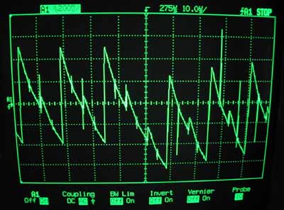
A bit time is 256 μs. The tag's id is periodic over 64 bit times, 16384 μs.
When there is no phase shift, the signal is a 125 kHz sinusoid slightly modulated by a 62.5 kHz sinusoid.
The modulation is greatly exaggerated in the figure.
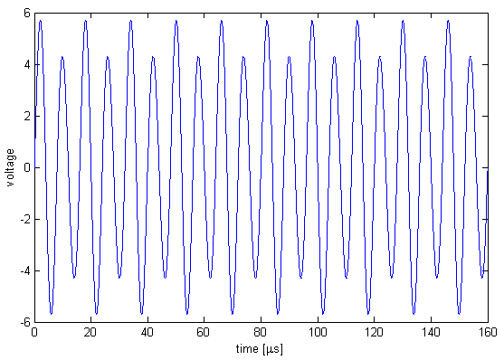
To indicate a bit transition, the tag inserts a phase shift of π.
There is always an even number of carrier cycles between phase shifts,
so that if the most recent phase shift was achieved by skipping a small-amplitude cycle
then the next phase shift will be achieved by skipping a large-amplitude cycle.
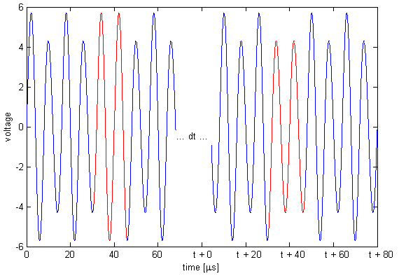
Since a bit time is 256 μs, phase shifts are an integer multiple of 256 μs apart.
Thus, in the above picture, we could have t = 256, 512, 768, ... μs.
A code consists of 64 bit times.
There are no transitions for the last 29 bits for all but one of the cards that I have tested.
Possibly the one card is in a newer format, or possibly it's just weird.
There appears to be some structure within the bits—if I get some of the bits wrong then the reader doesn't even beep,
but if I get others wrong then the reader still beeps but the door doesn't open.
I haven't had any need to figure out which are which though.
My first tag sort of disintegrated (too many flywires) so I built a new combination reader/tag.
In tag mode I chose to ignore the reader's carrier:
I just blast my own modulated carrier at the reader.
This works perfectly well, and you'd expect it to;
if we're not in phase with the reader's oscillator then we will be in a few hundred milliseconds.
(The beat frequency is ~1 Hz, for a variation of a few ppm, typical for a crystal).
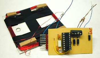
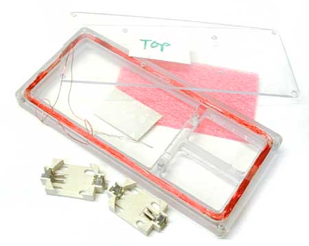
A Toy With Blinking Lights
The hardware to pretend to be a tag is very simple. The hardware to read a tag is not much more complicated; I could do it with a micro, a quad opamp, and a dozen passives. This meant that I could build a combination card reader/simulator in a few square inches of board space. Add a couple of lithium batteries and some nice plastics and I would have a clever and mostly useless pocket-sized toy. Of course I couldn't resist building it.
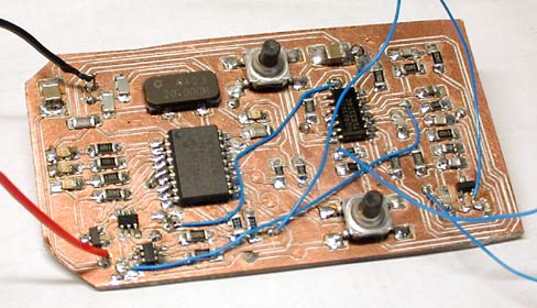
For a sense of scale, the PIC16F628 (largest IC) and the opamp are both SOICs. There aren't any unreasonably fine-pitch components on this board; the tightest are the SuperSOT FETs (bottom left), with 0.95 mm lead spacing.
The hardware is very similar to the larger reader/simulator described above. I decided not to attempt PSK demodulation; I just detect the modulation artifacts and use the hysteresis, so that I know that if the comparator output has changed state since I looked at it last then there has been a phase shift since then. This sacrifices a bit of sensitivity but my read range is small enough (by design, for reasonable battery life) that this doesn't bother me. This hardware could also be used for AM cards, if I ever came across one.
The PIC can kill power to the detector section with a couple of FET switches. This plus the PIC's sleep mode means that I can do on/off in software without ruining my battery life.
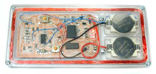
The circuit is again built on a milled PCB, with one signal layer and a ground plane.
The ground plane is split into analog (GND = 0V) and digital (V- = -3V) sections.
It is powered by a pair of CR2032 lithium coin cells. They determine the thickness of the device; the batteries, in a holder, are 0.217" thick.
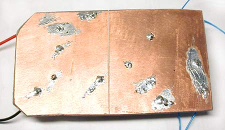
There are no connectors on the board because I couldn't find any low-profile surface mount connectors that I liked.
Instead there are test points to program the PIC and tune the coil;
I actually built a test/programming fixture (with pogo pins).
This is pretty easy with a CNC machine. P
ower and coil leads are soldered directly to the board.
The blue wires are mostly test points, for debugging only.
The 8 pin header connects to my PIC programmer.
All the plastics were routed from sheet on my milling machine, using an 1/8" carbide straight bit intended for use in wood.
Yes, the workpiece is held to the table by carpet tape; this is much cheaper than a vacuum chuck.
The top and bottom of the case are each 1/16" Lexan (polycarbonate); the core is milled from 6 mm Lexan sheet. The top has drilled holes for the actuators of the two tact switches on the PCB. I paid too much (more than a dollar each!) for the battery holders shown below because they make it very difficult to apply a reverse voltage to the circuit by mis-inserting the cell. The pink foam presses the board into contact with the lid so that the tact switch actuators project.
Both the top and bottom screw into the core with #2 tapping screws. I put a lot of effort into finding a local source for a methylene chloride solvent cement (so that I could weld the bottom on instead of screwing it) but I gave up after many failures. I first tried machine screws but small-diameter machine screws tend to have too many threads per inch to work in plastics. Next time I'd probably look for threaded inserts.
I left the wires long so that I can remove the the board from the plastics without desoldering anything. This is necessary to put it on the programming jig, and it helps when I'm trying to figure out whether I have a circuit-does-the-wrong-thing problem or a 125-kHz-pickup-on-everything problem.
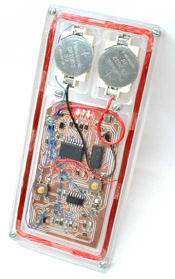
The user interface comprises four LEDs and the two tact switches. The software can currently read a card, store a single id, transmit that id over the air to a reader, blink out that id on the LEDs, and accept a new id on the tact switches. There is also a “sniff” mode, in which the detector is active but the coil is not powered; this allows me to read a card while a legitimate reader is powering it. (The read range of the cards is limited by the tag power requirements, not by reader sensitivity; it goes up substantially when another reader is powering the card.)
Most of the software is pretty straightforward. To transmit the id, I must apply a square wave with, on average, every other cycle missing. I do this entirely in software, flipping a GPIO every 4 μs. I managed to make this work on a 4 MHz device (4 cycles between edges); it's much easier on a 20 MHz device, though. The antenna is resonant around 125 kHz, so that it effectively bandpass filters the pulse train that I generate.
In the figure below, the blue trace is obtained by passing the red trace through a bandpass filter centred at twice the frequency of the pulse train:
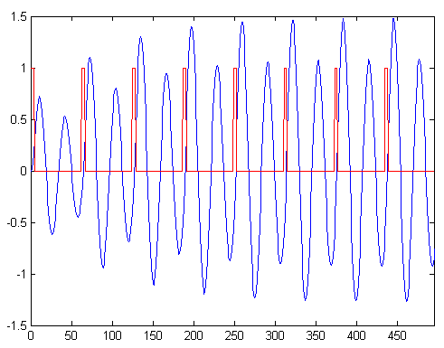
For the reader functionality I configure the PWM module to generate the unmodulated square wave so that I can be a bit sloppier with my timing.
I sync on the word by waiting for an edge after a long idle period (though this is of course unnecessary; I only need bit sync). Then I read the word into memory. Then, I read the word ten more times, comparing it against the recorded copy each time; if they all match then I decide that it's right, else I lose sync and try again. This works reasonably well, but if the card is held just barely outside the read range then I will eventually false-sync. This is bad, because there is no other verification. Legitimate readers can false-sync with no major repercussions, since they would just fail to open the door; the user would stand there waiting until the card was read correctly.
Security Implications
I can copy a proximity card at least as easily as I can take an impression of a key. This means that it's not a very good idea to reuse visitor cards without changing the id (and that it doesn't really matter whether you get the physical card back from the guy you just fired).
More insidiously, it's quite practical to read someone's card without removing it from their wallet. A bit of deliberate clumsiness, a reader up my sleeve, and I would have little trouble cloning anyone's card. I could also exploit the fact the distance at which the cards will be powered is less than the distance at which they can be read; if another reader is exciting the card then my reader can read that card from the other side of a wall!
This means that a sniffer concealed somewhere near a legitimate reader could intercept real transactions at a significant distance. This sort of attack is particularly good because the card repeats its id over and over as long as it is in the field, so that I could use signal processing techniques to combine multiple copies of the pattern to further improve my read range. This is easy—if I sample all 64 bits of the id then I don't have to get word-sync, and if I oversample then I don't even have to get bit-sync. Even if I capture the id with a few bit errors it is still useful; I could try the captured id, then every id with a Hamming distance of 1 from the captured id (one bit flipped), then 2, and so on. One or two bit errors would take seconds; three would take minutes.
If I were willing to spend money on a four (or even two) layer board then I could build a sniffer/reader much smaller than anything shown above. If I used black Lexan (or even acrylic) for the case then the device would look less like something that an image-conscious terrorist might carry. This would make it much easier to carry out the attacks outlined above.
All of these attacks can be stopped with a challenge/response scheme. I've seen brochures for cards and readers that do this; I guess it's not just a marketing gimmick.
Hardware Notes
The coil driver consists of an N/P FET pair, with the FETs working as switches.
For my initial reader I connected the drains together, like in a CMOS inverter.
This drove the RLC circuit that was the coil, the tuning cap, and a current-limiting resistor.
This has two flaws.
First, it has a software self-destruct mode;
if the input floats between the positive and negative rails then both FETs will conduct, shorting V+ to V-, and the FETs will get very, very hot.
This caught me because the PIC tri-states all its GPIOs when it's being programmed in system.
There was a bit of a shoot-through problem too; the switching transients got in to everything. Smaller FETs would actually have been better, but I just put some resistance between the drains, because I needed some resistance to limit the current anyways.
My layout seems to be reasonably good. There's hundreds of millivolts of noise on most of the signals around the PIC, but noise on the detector signals is in the tens of millivolts. More bypassing might have cleaned things up further. Not placing the circuit inside the antenna might also have helped....
The detector is rather poor.
When reading (or sniffing) from a large distance, it would be nice to be able to turn down the hysteresis to get some chance at a read. This is not currently possible. It's probably not worth messing with the envelope detector though; it would be better to build a proper PSK detector (by correlating and then integrating the peak detector output in hardware, or with a sharp notch filter to reject the 125 kHz component, allowing me to work only with the sidebands.).
The coin cells probably aren't a very good choice for this application considering the high peak currents—Panasonic's datasheet doesn't even mention what happens if you try to draw more than a milliamp. I don't know what would be better, though; thin batteries are hard to find.
The opamps that I use (TLC2274s) are not low-current. I knew this when I chose them but I assumed that they would only need to be powered when the coil was energized. In sniff mode this is not true; the coil is not driven, and I could even put the PIC to sleep and wake on an edge from the detector. Next time, I guess.
I was careless when I designed the power switching stuff; there were a couple of leakage paths that added almost 60 microamps of off current. I was able to fix this by depopulating a couple of components and faking out the functionality that they used to provide in software. Off current is about 4 μA. The CR2032s can deliver about 200 mAh, for a standby life comparable to the shelf life of the cells.
The presence of metallic objects inside the antenna probably does weird things. Certainly it detunes the coil a bit, and even after I tweaked it back to resonance the voltage on the coil was smaller (indicating that some of my battery life is going to eddy currents in the mounting screws).
I had a few interesting problems relating to 125 kHz pickup from the read coil. The wires from the board to the coil are quite vicious; seriously bad things happen if they rest on the analog traces.
I had a lot of trouble machining the polycarbonate until I got my feeds and speeds right. Too slow of a feed for your speed is very bad; the plastic melts, the cutter loads, friction increases and chip ejection goes to nothing, and you get thermal runaway. Once I figured that out everything went quite easily. Surface finish with an 0.015" finish pass was acceptable as machined almost everywhere. Where it wasn't I used the non-serrated edge of a hacksaw blade to clean it up.
Acrylic makes a nicer case than polycarbonate—it's more rigid and less prone to scratching. An acrylic case probably wouldn't survive a two foot drop onto concrete, though.
Future Plans
The toy described above is nice, but it could be better. I believe that I could sample the peak detector output directly (after AC-coupling it down) and do the demodulation in software. I have a very clever idea that uses the PIC's comparators and voltage reference module to do PSK detection, possibly one so clever that it works only in simulation. This would allow me to lose the opamp entirely. I could drive the coil from a few GPIOs tied together, at the cost of read range. This would get the design down to the micro plus some passives.
I'd also like to get rid of the split supply and run from a single 3 V rail. I think I'd have to do some sort of trick with multiple coils (like a transformer) to get a reasonable input impedance without an unreasonably high Q.
Alternatively, I could build a long range sniffer (better detector, one foot diameter read coil, enough current that it's just on the edge of melting, a motorcycle battery to power the thing...). This wouldn't be nearly as cool as a smaller version of my toy but it would be better for convincing people that the cards are insecure.
October 2003, Waterloo
the simplest possible rfid emulator
When looking for a low frequency RFID emulator for security testing purposes, you can find several designs out there.
However, their complexity can make you think twice before building one.
Is necessary that complexity? In some cases you don’t need too much functionality.
Just a simple RFID emulator without fancy capabilities.
How simple can be an emulator? Let’s see.
Look this!
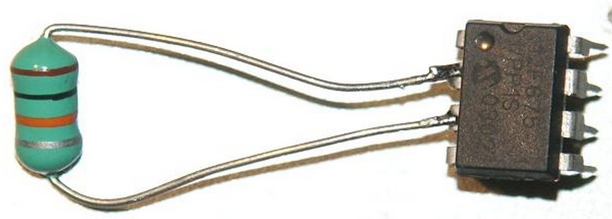

HOW IT WORKS?
In order to understand how this simple design can works, we have to consider the internal connections of the microcontroller IO ports.
Consulting the datasheet, we can observe that every IO pin has an internal parasite capacitor (around 5pF) and a pair of clamping diodes, as this diagram shows:
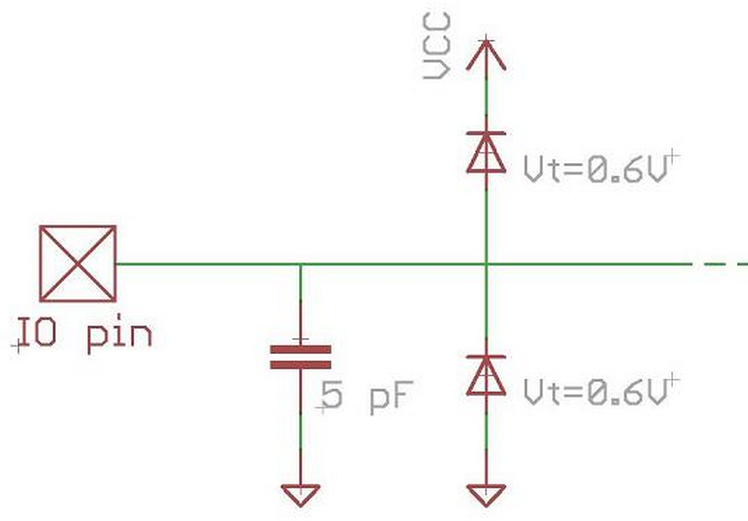
Considering internal capacitance and diodes, the result schematic of this simple emulator is something like:

The parasite capacitor in the IO pins and the external coil form a LC resonant circuit and act as an antenna. This antenna will pick up the carrier generated by the RFID reader.
The recovered carrier is rectified thanks to the bridge formed with the clamping diodes, feeding back the result signal to the power supply of the microcontroller.
Note that the coil (antenna) is connected to the GP5 / CLKIN / OSC1 port. This is important, but we will back to it later.
The other terminal of the coil is connected to the GP4 port. In order to transmit data to the RFID reader, we have to modulate the low frequency carrier by changing the coupling between the reader and tag antennas. We can achieve this by switching the GP4 as input (High-Impedance) or output (connected to GND).
THE FIRMWARE
Some knowledge on PIC assembler is requiered to understand perfectly this section.
Basically, The code for emulating a read-only tag is not more than a bunch of “well-timed” instructions that modify the GP4 state.
This microcontroller (like most of the modern PIC microcontrollers) has an internal oscillator. However, instead of using the internal oscillator, the firmware uses the RFID carrier, present in the GP4 pin, as the system clock.
This way, the firmware is simpler because there is no need to synchronize the data modulation (switching the GP4 pin to GND or High-Impedance) with the RFID carrier. The code execution is already synchronized with the carrier.
The oscillator block has a “relatively” high power consumption, so another reason for not using the internal oscillator is to save energy. And less power means longer reading distance.
As firmware example, you can download this ASM source. It emulates a EM4100 RFID tag, a very common tag.
The EM4100 [datasheet] is a read-only tag with 64 bits of memory and is usually found configured to work at 64 clocks per bit and with Manchester encoding.
The Manchester encoding implies that a ‘1’ encoded bit is transmitted “half-bit” (32 clocks) as ‘0’ and “half-bit” (32 clocks) as a ‘1’.
In this configuration, the ASM code for transmitting a ‘1’ encoded bit is:
BSF     TRISIO, GP4        ; GP4 as input (High-Impedance). Transmit a '0'.
NOP
NOP
NOP
NOP
NOP
NOP
NOP
BCF TRISIO, GP4 ; GP4 as output (GND). Transmit a '1'
NOP
NOP
NOP
NOP
NOP
NOP
NOP
Note that between the execution of the BSF and the BCF instructions there are exactly 8 instruction cycles. Considering that the PIC architecture uses 4 system clocks for executing one instruction, it means that pass exactly 32 carrier clocks between the two instructions.
A ‘0’ encoded bit is transmitted in a similar way.
The schematic with the cited improvements:
A 150 uH coil and a 10 nF capacitor are good values to start with.
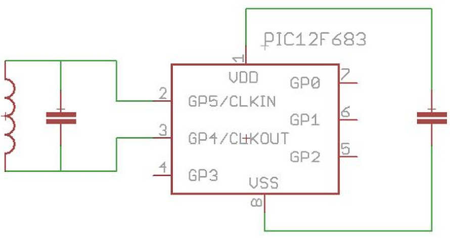
NOTES
The microcontroller used for this project is the PIC 12F683. However, any other PIC 12F (or even 16F) microcontroller is suitable for the emulator. The firmware should compile without any change.
Using a manufactured coil instead of homemade one can be tricky. Prepare yourself to do some try-outs.
Choose the biggest inductance possible because it will have a larger area. Be aware that some inductors can be covered with a conductive foil to isolate the coil from the EM noise.
The idea of creating a RFID emulator using just the microcontroller and a coil is not original mine.
This post from the Scanwidget’s Journal gave me the idea.
If you are a AVR fan instead of a PIC one, check that post.
;;;;;;;;;;;;;;;;;;;;;;;;;;;;;;;;;;;;;;;;;;;;;;;;;;;;;;;;;;;;;;;;;;;;;;;;;;;;
;; ;;
;; ;;
; OPEN RFID TAG - EM4100 TAG ;
;; ;;
;; ;;
;;;;;;;;;;;;;;;;;;;;;;;;;;;;;;;;;;;;;;;;;;;;;;;;;;;;;;;;;;;;;;;;;;;;;;;;;;;;
;; ;;
;; ;;
; ;
; Author: Ramiro Pareja ;
; E mail: ramiropareja -at- t4f -dot- org ;
; Web: www.t4f.org ;
; Date: 30/05/2009 ;
; ;
; Description: Simple EM4100 RFID emulator ;
; More info -> http://www.t4f.org ;
; ;
; License: Software released under the GPL 3 license; ;
; Commercial license avaliable under request; ;
; See www.t4f.org/license ;
;; ;;
;;; ;;;
;;;;;;;;;;;;;;;;;;;;;;;;;;;;;;;;;;;;;;;;;;;;;;;;;;;;;;;;;;;;;;;;;;;;;;;;;;;;;;;;
#include "p12f683.inc"
__CONFIG _WDT_OFF & _BOD_OFF & _PWRTE_ON & _EC_OSC
;;;;;;;;;;;;;;;;;;;;;;;;;;;;;;;;;;;;;;;;;;;;;;;;;;;;;;;;;;;;;;;;;;;;;;;;;;;;;;;;
;;; ;;;
;; ;;
; MACRO: TX ;
; Desc.: Transmits data to the reader ;
; Params.: DATA -> data to transmit ;
; NUM_BITS -> number of bits to transmit ;
; PARITY_CHECK -> calculates the parity bit ;
; ;
; Notes: ;
;; ;;
;;; ;;;
;;;;;;;;;;;;;;;;;;;;;;;;;;;;;;;;;;;;;;;;;;;;;;;;;;;;;;;;;;;;;;;;;;;;;;;;;;;;;;;;
TX MACRO DATA, NUM_BITS, PARITY_CHECK
LOCAL i = NUM_BITS
LOCAL tmp = DATA
LOCAL parity = 0
LOCAL mask = 0x01 << (NUM_BITS-1)
WHILE i > 0
IF (tmp & mask)
CALL _TX_manchester_one
parity = !parity
ELSE
CALL _TX_manchester_zero
ENDIF
tmp = tmp << 1
i -= 1
ENDW
IF (PARITY_CHECK == 1)
IF (parity)
CALL _TX_manchester_one
ELSE
CALL _TX_manchester_zero
ENDIF
ENDIF
ENDM
ORG 0x00
;;;;;;;;;;;;;;;;;;;;;;;;;;;;;;;;;;;;;;;;;;;;;;;;;;;;;;;;;;;;;;;;;;;;;;;;;;;;;;;;
;;; ;;;
;; ;;
; Function: _configuration ;
; Desc.: Configures the microcontroller ;
; ;
; Notes: If you want to port the firmware to another 12F or 16F micro, ;
; you have to change only this function. Be sure that you ;
; configure the IO ports as digital inputs. ;
;; ;;
;;; ;;;
;;;;;;;;;;;;;;;;;;;;;;;;;;;;;;;;;;;;;;;;;;;;;;;;;;;;;;;;;;;;;;;;;;;;;;;;;;;;;;;;
_configuration
BSF STATUS,RP0 ; Bank 1
CLRF ANSEL ; GPIOs as digital ports
BCF STATUS,RP0 ; Bank 0
MOVLW 07h ; Turning off the analog comparators
MOVWF CMCON0
CLRF ADCON0 ; turn off A/D convertor
;;;;;;;;;;;;;;;;;;;;;;;;;;;;;;;;;;;;;;;;;;;;;;;;;;;;;;;;;;;;;;;;;;;;;;;;;;;;;;;;
;;; ;;;
;; ;;
; Function: _main ;
; Desc.: Main program loopm. Transmits the data. ;
; ;
; Notes: The firmware emulates an EM4100 tag with the next memory map ;
; ;
; 111111111 <- Header ;
; 00011 00011 <- Manufacturer ID ;
; 00011 00011 00011 00011 <- Serial number ;
; 00011 00011 00011 00011 ;
; 11110 <- parity column and stop bit ;
;; ;;
;;; ;;;
;;;;;;;;;;;;;;;;;;;;;;;;;;;;;;;;;;;;;;;;;;;;;;;;;;;;;;;;;;;;;;;;;;;;;;;;;;;;;;;;
_main
BSF STATUS, RP0 ; Bank 1
; Transmits the header ('111111111')
TX 0x1FF, 9, 0
; Transmits the manufacturer ID (with parity bit)
TX 0x01, 4, 1
TX 0x01, 4, 1
; Transmits the serial number (with parity bit)
TX 0x01, 4, 1
TX 0x01, 4, 1
TX 0x01, 4, 1
TX 0x01, 4, 1
TX 0x01, 4, 1
TX 0x01, 4, 1
TX 0x01, 4, 1
TX 0x01, 4, 1
; Transmit the parity column (previosly calculated) and the stop bit ('0')
TX b'11110', 5, 0
bcf STATUS, RP0 ; Bank 0
goto _main ; Repeat the transmition
;;;;;;;;;;;;;;;;;;;;;;;;;;;;;;;;;;;;;;;;;;;;;;;;;;;;;;;;;;;;;;;;;;;;;;;;;;;;;;;;
;;; ;;;
;; ;;
; Function: _TX_manchester_one ;
; Desc.: Transmit a '1' ;
; ;
; Notes: Manchester encoding at 64 clocks per bit is used. ;
; To change the data rate, just add or remove NOP instructions ;
; Using a Biphase encoding would require more complex changes. ;
; However, you can transmit a biphase encoded memory map if you ;
; encode the raw data transmited as Manchester. ;
;; ;;
;;; ;;;
;;;;;;;;;;;;;;;;;;;;;;;;;;;;;;;;;;;;;;;;;;;;;;;;;;;;;;;;;;;;;;;;;;;;;;;;;;;;;;;;
_TX_manchester_one
BSF TRISIO, GP4 ; GP4 to High impedance. TX a zero
NOP ; Waiting for 32 clocks (8 instructions)
NOP
NOP
NOP
NOP
NOP
NOP
BCF TRISIO, GP4 ; GP4 to GND. TX a one
NOP ; Waiting for 32 clocks (8 instructions)
NOP
NOP
RETURN ; The RETURN and the next CALL
; instructions count as 16 clocks (4*4)
;;;;;;;;;;;;;;;;;;;;;;;;;;;;;;;;;;;;;;;;;;;;;;;;;;;;;;;;;;;;;;;;;;;;;;;;;;;;;;;;
;;; ;;;
;; ;;
; Function: _TX_manchester_zero ;
; Desc.: Transmit a '0' ;
; ;
; Notes: Manchester encoding at 64 clocks per bit is used. ;
; To change the data rate, just add or remove NOP instructions ;
; Using a Biphase encoding would require more complex changes. ;
; However, you can transmit a biphase encoded memory map if you ;
; encode the raw data transmited as Manchester. ;
;; ;;
;;; ;;;
;;;;;;;;;;;;;;;;;;;;;;;;;;;;;;;;;;;;;;;;;;;;;;;;;;;;;;;;;;;;;;;;;;;;;;;;;;;;;;;;
_TX_manchester_zero
BCF TRISIO, GP4 ; GP4 to GND. TX a one
NOP ; Waiting for 32 clocks (8 instructions)
NOP
NOP
NOP
NOP
NOP
NOP
BSF TRISIO, GP4 ; GP4 to High impedance. TX a zero
NOP ; Waiting for 32 clocks (8 instructions)
NOP
NOP
RETURN ; The RETURN and the next CALL
; instructions count as 16 clocks (4*4)
END
;;;;;;;;;;;;;;;;;;;;;;;;;;;;;;;;;;;;;;;;;;;;;;;;;;;;;;;;;;;;;;;;;;;;;;;;;;;;
;; ;;
;; ;;
; OPEN RFID TAG - RFID DETECTOR ;
;; ;;
;; ;;
;;;;;;;;;;;;;;;;;;;;;;;;;;;;;;;;;;;;;;;;;;;;;;;;;;;;;;;;;;;;;;;;;;;;;;;;;;;;
;; ;;
;; ;;
; ;
; Author: Ramiro Pareja ;
; E mail: ramiropareja -at- t4f -dot- org ;
; Web: www.t4f.org ;
; Date: 15/11/2009 ;
; Version: 0.4 ;
; ;
; Description: Detects the frequency of the RFID carrier ;
; The faster the LEDs blink, the nearer the carrier is from ;
; the reference frequency (LED1: 125KHz, LED2: 135KHz) ;
; More info -> http://www.t4f.org ;
; ;
; License: Software released under the GPL 3 license; ;
; Commercial license avaliable under request; ;
; See www.t4f.org/license ;
;; ;;
;;; ;;;
;;;;;;;;;;;;;;;;;;;;;;;;;;;;;;;;;;;;;;;;;;;;;;;;;;;;;;;;;;;;;;;;;;;;;;;;;;;;;;;;
#include "p12f683.inc"
#include "..\Common\io.inc"
#include "..\Common\misc.inc"
__CONFIG _CP_ON & _CPD_OFF & _WDT_OFF & _BOD_OFF & _PWRTE_ON & _INTRC_OSC_NOCLKOUT & _MCLRE_ON & _IESO_OFF & _FCMEN_OFF
EXTERN _initIO
EXTERN _pauseX1mS
;;;;;;;;;;;;;;;;;;;;;;;;;;;;;;;;;;;;;;;;;;;;;;;;;;;;;;;;;;;;;;;;;;;;;;;;;;;;;;;;
;;; ;;;
;; DEFINITIONS ;;
;;; ;;;
;;;;;;;;;;;;;;;;;;;;;;;;;;;;;;;;;;;;;;;;;;;;;;;;;;;;;;;;;;;;;;;;;;;;;;;;;;;;;;;;
;;;;;;;;;;;;;;;;;;;;;;;;;;;;;;;;;;;;;;;;;;;;;;;;;;;;;;;;;;;;;;;;;;;;;;;;;;;;;;;;
;;; ;;;
;; VARIABLES ;;
;;; ;;;
;;;;;;;;;;;;;;;;;;;;;;;;;;;;;;;;;;;;;;;;;;;;;;;;;;;;;;;;;;;;;;;;;;;;;;;;;;;;;;;;
UDATA
; Context vars.
W_TEMP RES 1
STATUS_TEMP RES 1
PERIOD RES 1
BLINK125 RES 1
BLINK135 RES 1
BLINK_COUNTER RES 1
TRASH UDATA 0xA0
TRASH RES .32 ; WARNING! We reserve all the GPRs in the BANK1
; to avoid the linker using them.
; This way, we force the linker to alloc all
; the vars in the BANK0.
;
; The "good" way to do this is doing a linker
; script.
;;;;;;;;;;;;;;;;;;;;;;;;;;;;;;;;;;;;;;;;;;;;;;;;;;;;;;;;;;;;;;;;;;;;;;;;;;;;;;;;
;;; ;;;
;; CODE ;;
;;; ;;;
;;;;;;;;;;;;;;;;;;;;;;;;;;;;;;;;;;;;;;;;;;;;;;;;;;;;;;;;;;;;;;;;;;;;;;;;;;;;;;;;
RST_VECTOR CODE 0x0000
GOTO _start
INT_VECTOR CODE 0X0004
; Save the actual context
MOVWF W_TEMP
SWAPF STATUS,W
BCF STATUS,RP0
MOVWF STATUS_TEMP
; Check the TMR1 interruption
BTFSC PIR1, TMR1IF
CALL _ISRTimer1
; Restore the context
SWAPF STATUS_TEMP,W
MOVWF STATUS
SWAPF W_TEMP,F
SWAPF W_TEMP,W
RETFIE
_start
CALL _initIO ; Init IO
CALL _initTimer1
CALL _initTimer0
CLRF PERIOD
MOVLW .32
MOVWF BLINK_COUNTER
_main
MOVFW PERIOD ; Wait until PERIOD != 0 (TMR1 INT)
BTFSC STATUS, Z
GOTO $-2
_blink
; BLINK125 = ABS(Period-200) & 0x1F
MOVLW .200 ; W = Period - 200
SUBWF PERIOD, W
BTFSC STATUS, C ; Period - 200 <0?
GOTO $+3
MOVFW PERIOD ; W = 200 - PERIOD
SUBLW .200
ANDLW 0x1F
MOVWF BLINK125
; BLINK135 = ABS(Period-185) & 0x1F
MOVLW .185 ; W = Period - 185
SUBWF PERIOD, W
BTFSC STATUS, C ; Period - 185 <0?
GOTO $+3
MOVFW PERIOD ; W = 185 - PERIOD
SUBLW .185
ANDLW 0x1F
MOVWF BLINK135
MOVFW BLINK125 ; W = BLINK_COUNTER - BLINK125
SUBWF BLINK_COUNTER,W
BTFSS STATUS, C ; BLINK_COUNTER < BLINK125
LED1_OFF
BTFSC STATUS, C ; BLINK_COUNTER >= BLINK125
LED1_ON
MOVFW BLINK135 ; W = BLINK_COUNTER - BLINK135
SUBWF BLINK_COUNTER,W
BTFSS STATUS, C ; BLINK_COUNTER < BLINK135
LED2_OFF
BTFSC STATUS, C ; BLINK_COUNTER >= BLINK135
LED2_ON
MOVLW .30
CALL _pauseX1mS
DECFSZ BLINK_COUNTER, F
GOTO _blink
MOVLW .32
MOVWF BLINK_COUNTER
GOTO _blink
;;;;;;;;;;;;;;;;;;;;;;;;;;;;;;;;;;;;;;;;;;;;;;;;;;;;;;;;;;;;;;;;;;;;;;;;;;;;;;;;
;;; ;;;
;; ;;
; Function: _initTimer1 ;
; Desc.: Initialize the Timer1 ;
; Vars: ;
; ;
; Notes: ;
;; ;;
;;; ;;;
;;;;;;;;;;;;;;;;;;;;;;;;;;;;;;;;;;;;;;;;;;;;;;;;;;;;;;;;;;;;;;;;;;;;;;;;;;;;;;;;
_initTimer1
BANKSEL PIE1 ; Bank 1
CLRF PIE1 ; Activate the Timer1 Interruption
BSF PIE1, TMR1IE
BANKSEL PIR1 ; Bank 0
BCF PIR1, TMR1IF ; Clear the TMR1IF flag
MOVLW b'11000000' ; Activate GIE and PEIE
IORWF INTCON, F
MOVLW 0xFF ; Write the Timer1
MOVWF TMR1H
MOVLW -.200
MOVWF TMR1L
MOVLW b'00000111' ; Timer1: external clock source, synchronous, no prescaler.
MOVWF T1CON ; Timer1 config
RETURN
;;;;;;;;;;;;;;;;;;;;;;;;;;;;;;;;;;;;;;;;;;;;;;;;;;;;;;;;;;;;;;;;;;;;;;;;;;;;;;;;
;;; ;;;
;; ;;
; Function: _initTimer0 ;
; Desc.: Initialize the Timer0 ;
; Vars: ;
; ;
; Notes: ;
;; ;;
;;; ;;;
;;;;;;;;;;;;;;;;;;;;;;;;;;;;;;;;;;;;;;;;;;;;;;;;;;;;;;;;;;;;;;;;;;;;;;;;;;;;;;;;
_initTimer0
BANKSEL OPTION_REG ; Bank 1
MOVLW b'00000010' ; Timer0: internal clock source, prescaler 8X
MOVWF OPTION_REG
BANKSEL TMR0 ; Bank 0
CLRF TMR0 ; Clear TMR0
RETURN
;;;;;;;;;;;;;;;;;;;;;;;;;;;;;;;;;;;;;;;;;;;;;;;;;;;;;;;;;;;;;;;;;;;;;;;;;;;;;;;;
;;; ;;;
;; ;;
; Function: _ISRTimer1RF ;
; Desc.: Timer1 Interruption Service Routine ;
; Vars: ;
; ;
; Notes: ;
;; ;;
;;; ;;;
;;;;;;;;;;;;;;;;;;;;;;;;;;;;;;;;;;;;;;;;;;;;;;;;;;;;;;;;;;;;;;;;;;;;;;;;;;;;;;;;
_ISRTimer1
BCF PIR1, TMR1IF ; Cleart the TMR1F flag
BANKSEL PIE1 ; Bank 1
BTFSS PIE1, TMR1IE ; Check for ghost interrupts
RETURN ; WARNING! Return with the Bank 1 selected
BANKSEL TMR1H ; Bank 0
MOVFW TMR0 ; Save the period
ADDLW -.1 ; Compensate the 15 instructions that are <- Should be -.2!
MOVWF PERIOD ; executed after the interruption.
MOVLW 0xFF ; Write the Timer1
MOVWF TMR1H
CLRF TMR0
MOVLW -.200
MOVWF TMR1L
RETURN
END
the open rfid tag
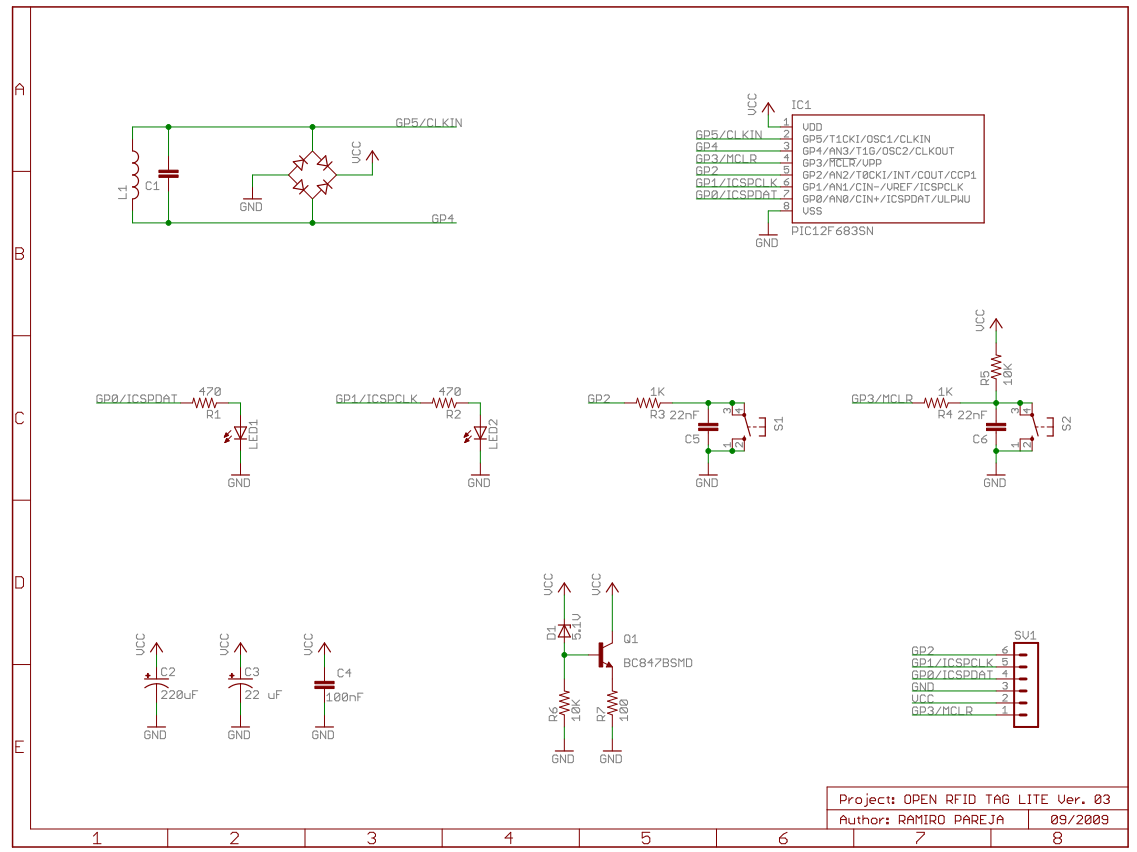
The first thing that we need to add is a simple user interface. It can be useful for controlling the tag behavior and for getting some feedback about the software status.
SPST buttons connected to the GP2 and GP3 pins are the input interface.
Two capacitors (C5 and C6) have been connected in parallel with each button to debounce the signal. Note that the GP3 pin has a pull-up resistor (R5) and GP2 has not, because it uses the internal programmable pull-up. Remember that the PIC 12F* devices have internal programmable pull-ups in every IO pin except GP3.
The 1K resistors R3 and R4 isolates the IO pins from the capacitors. That is needed, for example, to use a ICSP programmer or a debugger. Without the isolation, the capacitor could load the GP3/#MCLR/Vpp pin, avoiding the ICSP programmer to set the programming voltage and preventing the microcontroller from entering into programming mode.
As “output device”, we use two LEDs polarized through 470 ohms resistors (R1 and R2).
Be careful when using the LED in your firmware. Each led can consume up to 8 mA, several time more than the rest of the circuit. Turning on a LED can load too much the antenna coil and it could be interpreted by the reader as a carrier modulation. Moreover, if the antenna has not enough magnetical flux, it can make the power supply voltage to drop below the minimum.
POWER SUPPLY
When using the “simplest possible RFID emulator”, the first thing that you realize is that it has a not very long reading distance.
Creating a helicoidal coil antenna and tunning it properly helps a lot. However, the reading distance is still shorter than with a “real” RFID tag.
The problem is the way to obtain the energy from the carrier signal.
We are using the bridge rectifier formed by the clamping diodes to extract a power supply signal.
Those internal diodes have a forward voltage of 0.6V, causing it a drop of 1.2 volts in the rectified power signal.
Using a external bridge formed by four Schottky diodes will save us more than 600 mV. The omnipresent 1N5819 (with a Vf=0.2V @ 10mA) can be perfect for the task.
In next two images, you can appreciate the difference between using or not using the Schottky bridge rectifier.
The blue trace is the Vcc signal rectified with the Schottky bridge, the green one is without the Schottky diodes and the yellow one is the carrier signal measured in GP5 pin. In both images the oscilloscope was set to 500 mV/div and 4uS/div.
As you can see, using the Schottky diodes instead the internal clamping diodes can save more than 0.6 volts.
More capacitors are added for filtering the power signal. A electrolytic (C4), a tantalum (C3) and a ceramic (C1) capacitors are used. Not all of them are required, but it helps to minimize the impact of high current peaks when, for example, lighting on a LED or using the 8 internal MHz oscillator.
In the bottom oscillograms notice the difference in the use of Schottky diodes or ordinary in bringing the carrier frequency.
Blue: = 2.03V
Green: = 1.36V
Yellow: Max. = 2.27V
Blue line shows the power signal using Schottky diodes.
Green line is without Schottky diodes.
Yellow line is the signal induced in the coil reaching (GP5) processor.
As noted in the use of Schottky diodes compared with ordinary save about 0.6 volts.
AUTOMATIC GAIN CONTROL (AGC)
First of all, this is not a proper ACG… but I liked the name
Most of the time, the rectificated power supply will not be high enough ( >6V) to ruin any of the parts.
However, the possibility could be given if the reader creates enough magnetic field.
In order to avoid this situation, a protection circuit has been added.
While the power supply voltage is below 5.1 volts, the zenner diode (D1) does not conduct.
The base of the transistor (Q1) is tied to GND and is switched off.
How ever, when the Vcc voltage reaches the 5.1 threshold, the transistor starts to conduct current through the 100 ohms resistor (R7).
This current loads the antenna coil and makes the Vcc voltage to drop.
Automatic overvoltage protection
In most cases the voltage that is induced in the coil can not exceed 6V,
and it does not have risk to damage any of the elements.
But sometimes, under certain conditions - in a strong magnetic field or a sharp magnetization coil
(sudden skidding to a receiver) can form a peak above the maximum voltage that can kill CPU.
To prevent the risk of damage from surges, we applied the following schematic.
If the voltage is below 5.1V zener diode (D1) is blocked.
The base of the transistor (Q1) is "GND" and also blocked.
At a time when the supply voltage jump over 5.1V. Zener diode opens and unlocks respectively transistor (Q1).
On (R7) forms a voltage drop with power sufficient to load the coil so that the supply voltage drops below 5.1V
ICSP CONNECTOR
A 6 pins connector has been added. It allows an easy access to the microcontroller pins. It can be used for programming/debugging or as input/output device (Example: RS232 bootloader)
The connector’s pin-out is the same than the used by the PicKit2 programmer/debugger. You can buy one for less than 30€ or doing it yourself. Of course, you can use any other programmer like a JDM.
Selecting useful signal
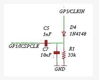
As mentioned above there are types of cards that can accept data sent by the reader.
Usually this operation is used to write data to the card processor (for programming card of our choice).
Reader transmits data to card memory as the same way as the card reader sends this data to -
modulated radio frequency carrier that is accepted by the antenna.
To empower our emulator to read and process this information be necessary
to create a circuit that reads, decodes and sends this information to the processor.
Later it was recorded in himself to play.
To do so, demodulate the carrier frequency to remove it only useful signal
and the easiest way for us is using the "Envelope detector"
OPEN RFID TAG LITE VERSION 0.3
ADDING THE “WRITE” CAPABILITY
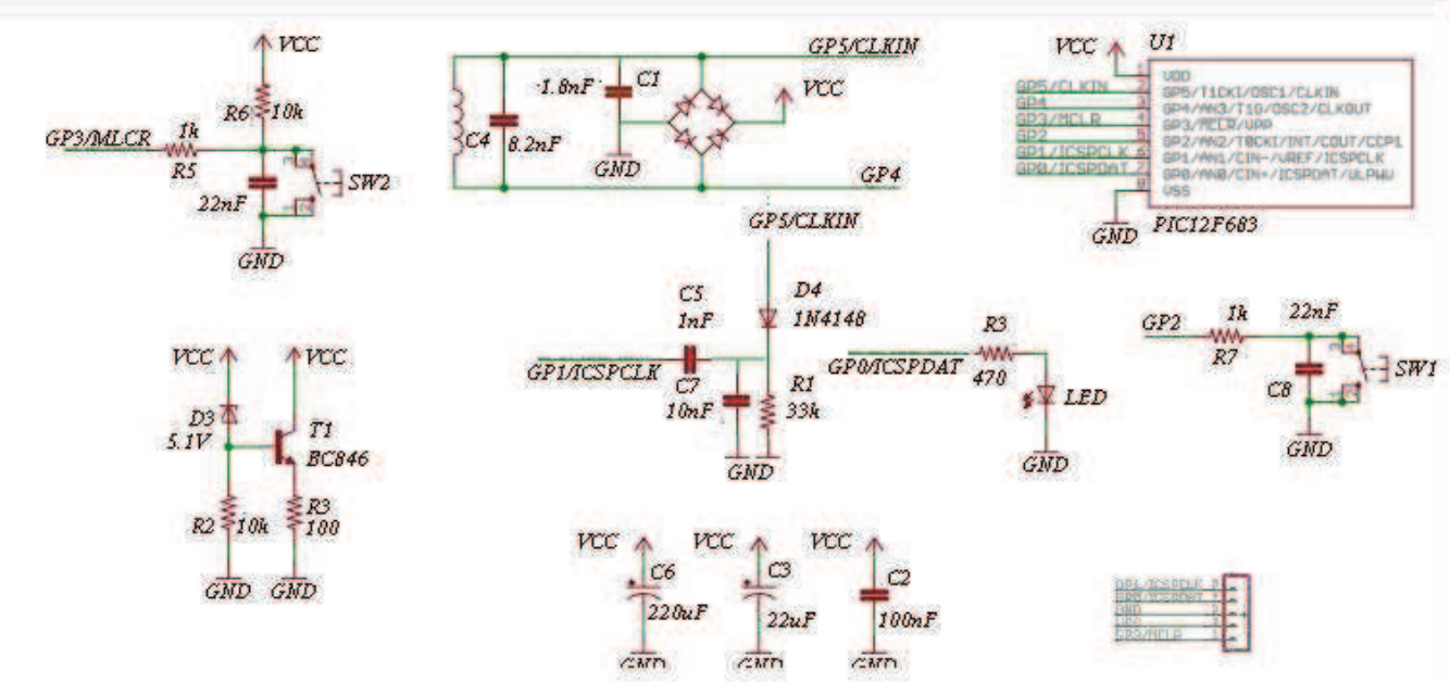
The hardware described until now allows to emulate almost any “READ ONLY” tag, which are those tags that send data (normally a serial or a unique ID number) to the reader as soon as the RF carrier is detected.
There are also other more complex tags that can receive commands from the reader. Normally this feature is used to write data in the memory map of the RFID tag, but other more interesting functions can be implemented like password or “Challenge-Response” authentication.
The reader will send the command to the tag in the same way that the tag send data to the reader: modulating the RF carrier by loading the antenna coil.
We have to demodulate the RF carrier in order to extract the modulating signal, and the simplest way to do this is using an “envelope detector” circuit like this:

The diode D4 rectifies the carrier and charges the capacitor C7 when the carrier signal amplitude increases.
When the carrier amplitude decreases the capacitor is discharged trough the resistor R8 (no current will “flow back” trough the diode).
The output signal is the envelope of the carrier… that is, the modulating signal that contain the data information
Green line: Modulated carrier input of the Envelope detector
Yellow: Modulating signal at the output of the detector
The resulting signal is connected to a coupling capacitor C8 to block the DC voltage
and the coupled output is connected to the internal voltage comparator of the PIC microcontroller.

Green line: before unleashing a constant component
Yellow line: after untying the constant component
White line: GND
Reference: 0.5V/V-div 0.4ms/H-div
The voltage comparator will compare the demodulated signal with a voltage reference (0.1 volts aprox, software defined)
and the output will be a “regenerated” signal similar to the data signal transmitted by the reader, ready to be decoded and processed
After untying the signal enters the integrated comparator the PIC processor.
Comparator compares the CPU voltage detect signal of 0.1 volts (software defined)
and the output signal is generated close to the signal sent by the reader, ready for decoding and processing.
Yellow: the input of the comparator (0.2V / V-div)
Green: the output of the comparator (1V / V-div)
White: GND
WARNING!!!
As you can see in the images, as consequence of the DC coupling, the comparator input signal is negative (< GND) in half of the cycle.
According to the microcontroller datasheet, a -0.3V voltage at the input of a I/O pin can blow that pin.
I haven’t blow any PIC yet, but keep in mind that you are stressing the microcontroller and it could be fatal.
DOING “MATHS”
The values of the capacitor (C7) and resistor (R8) of the envelope detector has to be correctly calculated.
They both form a low-pass filter whose cutoff frecuency (flp) is
The cutoff frecuency has to be high enough to pass the frequency of the modulating signal (fm)
but low enough to block the frequency of the carrier signal (fc).
If flp is too high, the carrier signal will pass and some ripple (noise) will appear in the filtered signal.
However if flp is too low, the modulating signal will be also filtered, and the output will be “clipped”.
Ideally, we have to choose a flp value such as:
Let’s calculate R and C!!!
fc = 125 KHz
fm = 1953.125 Hz
In the next image, the effects of choosing a too low flp value are show:

Yellow: R=100K C=10nF flp=1000Hz
Blue: R=56K C=10nF flp=1785Hz
The output signal should be “square shaped”, but we can observe
how a low flp introduces a distortion in the output signal by “rounding off” the falling edges.
More rounded as lower is the flp.
In order to avoid this “clipping” effect, flp has to be higher than fm (1953.125 Hz),
but not much higher because it could appear some “ripple” effects:
The chosen design values are:
flp = 3030 Hz
R = 33 Kohms
C = 10 nF
3030 Hz should be enough to filter correctly the 1953 Hz signal without having too much ripple noise, neither too “clipping”.
If you want to support a faster encoding scheme, you could have problems with the ripple noise.
In that case, a more complex filtering network is required.
But don’t worry… 3030 Hz is enough to emulate almost any low frequency RFID tag.
OPEN RFID TAG LITE 0.4
The next version of the Open RFID TAG lite has all the modifications to support data reception.
This will allow not only to emulate R/W tags, but also sniff communications and some other interesting features.
People ask me when I am going to finish the 0.4 design. Well… the answer is “as soon as Microchip decide to release the PIC 12F1822″.
One important feature I want to add to the next version of the Open RFID Tag is the ability to program the firmware using the RS232 port or using a RFID writer. To implement this, the microcontroller has to be “self-writable” and no actual PIC12F microcontroller support this and has EEPROM.
Moreover, the 12F1822 has – or will have – an internal 32 MHz clock, much faster than the actual 8 MHz. This speed improvement will be useful to implement some complex algorithms like the HiTAG encryption.
Expect this microcontroller to be released in Q1 of 2010…
FIRMWARES
Here you can download the software for the OPEN RFID Tag Lite. Documentation is still needed!!!!
The actual version is the 0.4 and includes:
- Multimap emulatorStores up to 12 different RFID memory maps (Manchester/Biphase encoding and different data rate are supported). Pressing the button 1, you can choose which one to emulate.A RS232 bootloader is implemented to change the memory maps. Commands:
- p: prints the stored memory maps.
- wABCCDDXXXXXXXX : writes a memory map. If the command is well constructed, it returns “OK”
- A is the number of the memory map. 1 Byte in hex. Values from 0 to B
- B is the encoding scheme. 1 byte in ASCII. ‘b’ form Biphase , ‘m’ for Manchester
- CC is the data rate. 2 bytes in hex.
- DD is the map size. 2 bytes in hex. Maximal value: 0x0F (firmware limited)
- XXXXXXXXX are the memory map bytes. DD bytes in hex.
- Frequency counterDetects a low frequency RFID reader and shows you the frequency of the carrier (from 115KHz to 145KHz).
LED1 represents 125 KHz and LED2 represents 135Khz. The LEDs blink proportionally to the received carrier. Examples:- 115 KHz carrier: LED1 blinks very slowly. LED2 is off
- 120 KHz carrier: LED1 and LED2 blink slowly. LED2 is blinking slower than LED1
- 125 KHz carrier: LED1 is on but do not blink. LED2 is blinking slowly.
- 130 KHz carrier: LED1 and LED2 blink slowly and at the same rate.
- 135 KHz carrier: LED2 is on but do not blink. LED1 is blinking slowly.
- ….
- Timing AttackIt performs a timing attack. The tag will transmit a memory map and will measure the time between the end of the transmission and denial event occurs. The event can be a rise edge of a signal measured inside the reader circuit (intrusive attack) or can be an acoustic or light signal (non intrusive attack). In this last case, you have to attach to the Open RFID Tag a circuit like an microphone or a light detector.The RS232 connection is used to program the transmitted memory map and read the measured times.
A PC-side software (not provided) is needed to perform the calculations and to decide which memory map try next.
OTHER FIRMWARES
These link has a VERY experimental firmware for cloning RFID tags “on the fly” and 100% passive. You can read more about it here.
- EM4100 Cloner
DOWNLOAD
These are old firmwares that can be useful.
- Brute-Force & Multimap ALL-in-1
This is the old 0.2 version of the firmware. I have not yet ported the “Brute Force Attack” to the 0.4 version of the firmware, so you have to use this old one.
It is commented in spanish and the code is a mess…DOWNLOAD - EM4100 emulator
A simple EM4100 emulator.
DOWNLOAD
HOW IT WORKS
RFID emulator
The underground waste containers in my neighborhood used to have an access system based on Texas Instruments’ TIRIS RFID tags.
The tags contain a 64-bit read-only identifier that is read using a low-frequency (LF) electromagnetic field of around 134 kHz.
Data bits are modulated using Frequency Shift Keying (FSK).
Since the system was fairly simple and involved signals of relatively low frequencies,
I decided to have a go at creating a microcontroller based solution to emulate and read these RFID tags.
Analog front-end
The main problem would be the design of the analog front-end.
A tuned coil, driven at the correct frequencies, was needed to emulate an authentic tag and to be able to read other tags.
An amplification and filtering stage was required to receive the often small return-signals of the tags.
Signal modulation and demodulation would be done entirely using the PIC microcontroller.
The software was coded using assembly to have better control of the strict signal timings.
The initial analog front-end was based on a pair of bipolar transistors to drive the coil.
A diode clamping section was needed to prevent the signal levels from getting too high for the microcontroller input.
This design didn’t work that well in practice because of the lack of amplification.
It could emulate tags but wasn’t able to read them and it also needed a more elaborate transistor biasing circuit.
Searching for better solutions, I found an Elektor article (TIRIS RFID Reader – October 2005),
describing an analog interface containing an amplification stage using op-amps (NE5532)
and a driving section using P- and N-channel MOSFETs.
I based my design for the most part on the design from this article with only minor changes to the components used.
The images below show the prototype of this improved design on breadboard,
with the microcontroller on the bottom and the analog front-end on a separate PCB on top, to reduce unwanted noise.
The prototyping PCB in the top-right corner, shown in detail in the right image, contains the SMD read-coil and tuning capacitors.
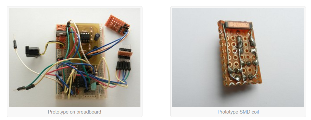
Final hardware
After the prototype on breadboard was working, I started designing the final hardware. The goal was to make the emulator portable, so I could easily use it outdoors. I decided to use a 9V battery to power it because it has enough capacity and it’s simple to convert to 5V using a linear regulator. The following schematic shows the completed design, including microcontroller, analog front-end, user-interface and power supply.
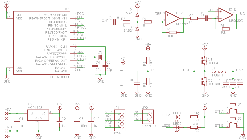
Coil L1 measures 1.08 mH and resonates at the correct frequency with the addition of 1220 pF of tuning capacitance (C9-C11). The coil is driven by two SMD FETs (Q1 and Q2) and delivers its signal (CAP) via a diode clamping stage (D1 and D2), to the dual op-amps of IC1. The diodes also bias the signal to around half the supply voltage (~2.5V). A reference voltage for the op-amps and the microcontroller is generated using 10 kΩ resistors R8 and R9 and 10 µF capacitor C8. The output signal of IC1 (SIG) is connected to the comparator input of the PIC.
The corresponding PCBs measure 29.5 x 50 mm and were designed to use mostly SMD components.
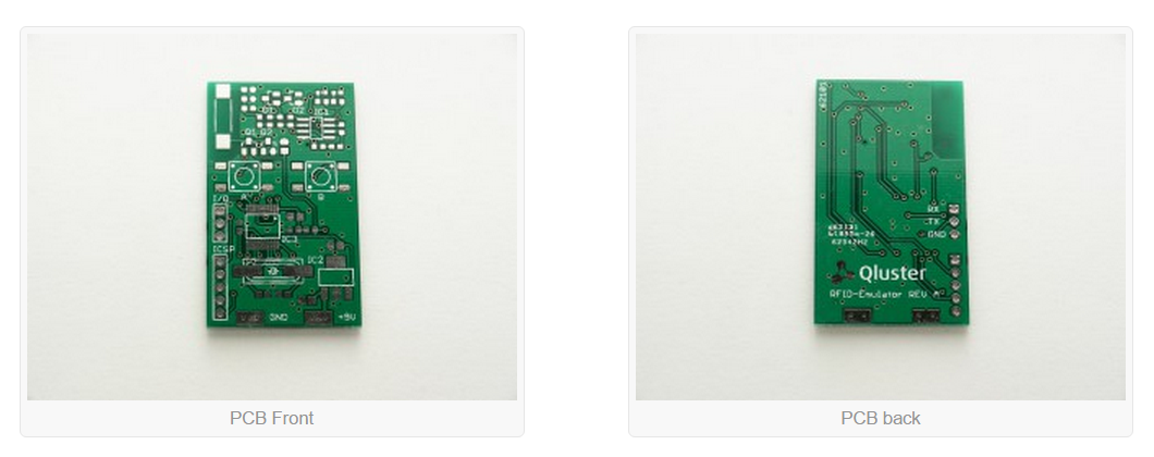
The populated PCB is shown below. It is mounted on a Keystone 1294 9V battery holder with slightly bent solder tabs. The coil at the top-left is a Coilcraft 4308RV series 1.08 mH RFID transponder coil (4308RV-115X). This SMD coil has a slightly reduced operating range compared to a full-size coil, but is far more portable and works almost as well. The two buttons can be controlled with one hand and the LEDs give feedback on the current operating state. The PCB also features connectors for serial communications and in-circuit reprogramming of the microcontroller.

Schematic and PCB layout are available in the downloads section.
Software
Transmitting tag data is accomplished by switching the coil output according to precisely timed bit-sequences. Delays are generated by jumping into a delay-table at specific locations. Every instruction used has a specific delay, so a lot of care has to be taken to output a correctly timed signal. For receiving, the internal comparator is wired to the CCP module in such a way that an interrupt is triggered on a rising edge of the input signal. This allows the software to measure the frequency of the input signal using a timer, and determine the value of the bits received.
Spoofer RFID

1 Arduino Uno ou Nano
1 keypad
1 LCD avec un expandeur I2C (PCF8574)
4 diode 1N4148,
1 zener 4.7v,
1 résistance de 100K,
1 condensateur de 1nF,
Application numérique: L=1.62mH et C=1nF, f0=125kHz
//SPOOFER RIFD
//Original work: http://hackaday.com/2010/11/28/rfid-spoofer-with-code-and-instructions/
//Programme initial par SKYWODD: https://skyduino.wordpress.com/2011/06/07/spoofer-rfid/
//Modification par J. GRISOLIA from AirDuino - 2015 -

#include <Wire.h>
#include <LiquidCrystal_I2C.h>
#include <Keypad.h>

LiquidCrystal_I2C lcd(0x27,16,2);  // set the LCD address to 0x27 for a 16 chars and 2 line display

const byte rows = 4;
const byte cols = 4;
char keys[rows][cols] =
{
{'1', '2', '3', 'A'},
{'4', '5', '6', 'B'},
{'7', '8', '9', 'C'},
{'F', '0', 'E', 'D'}
};
byte rowPins[rows] = {
  A0, A1, A2, A3};
byte colPins[cols] = {
  9, 8, 7, 6};
Keypad keypad = Keypad( makeKeymap(keys), rowPins, colPins, rows, cols );

#define coil_pin 12
#define DEBUG
#define longueur_code_RFID 10 //longueur du mot RFID à capter
#define nombre_bits_RFID 64 // nombre total de bit à transmettre dans le protocole EM4100
#define compte_a_rebours 5 //compte à rebours en secondes avant de spoofer la carte

char data[longueur_code_RFID];
int data_count =0;

//EM4100 Protocole (from EM Microelectronic):

//64 bits en tout:
// 9 bit de Header contenant chacun 1: These bits are used as a marker sequence to indicate the beginning of the string
// 8 bits de Version Number ou Customer ID: D00 à D03 + P0 et D04 à D07 + P1
//32 bits: 10 groups of 4 data and 1 even parity bits.
//4 bits of column parity (Even) and a stop bit (0)
//Shown here is an example string for a proximity card that has the data   $06 (version number), and $001259E3 as a data string.
// 111111111 | 0000 0|0110 0|0000 0|0000 0|0001 1|0010 1|0101 0|1001 0|1110 1|0011 0|0100|0
//               0      6      0     0       1      2      5      9     E      3
// the RFID transponder is able to transmit its data by modulating the RF field of the Reader.
//Here we discuss 3 popular modulation schemes:
// Manchester Encoding.
// BiPhase Encoding.
// PSK Encoding.
// The frequency of the synchronizing clock then simply becomes the frequency of the RF field used.
// RFID system clock frequencies vary according to the application required.  In low frequency, short distance sensing of Tags the typical band used is between 100-150Khz. For longer range sensing a system frequency of 13.56Mhz might be used, or other frequency as the application requires
//The length of each bit is specified in terms of clock cycles. For the EM4100 protocol bit lengths can be either 64, 32, or 16 Clock cycles.

//Manchester Encoding Scheme.
//With Manchester Encoding a Tag will produce a level transition in the middle of the bit period. A low to high
//transition represents a logic 1 state, while a high to low transition represents a logic 0 state.

/* 9bit HEADER *//* ID *//* ID *//*                      DATA 32bits + 8 bits parity                                 *//* CRC */
int spoofed_card[nombre_bits_RFID] = {
  1,1,1,1,1,1,1,1,1, 1,1,1,1,0 ,1,1,1,1,0, 1,1,1,1,0 ,1,1,1,1,0, 1,1,1,1,0 ,1,1,1,1,0, 1,1,1,1,0 ,1,1,1,1,0, 1,1,1,1,0 ,1,1,1,1,0, 0,0,0,0,0};
//<--  HEADER   --> |D0      P0 D4      P1|D8D9   P2|D13 D14    D18  D19   D23 D24    D28  D29   D33 D34     D38 D39   D43 D44    D48  D49   D53 D54    D58  D59   D63
//int spoofed_card[64] = {
//  1,1,1,1,1,1,1,1,1, 1,1,1,1,0 ,1,1,1,1,0, 1,1,1,1,0 ,1,1,1,1,0, 1,1,1,1,0 ,1,1,1,1,0, 1,1,1,1,0 ,1,1,1,1,0, 1,1,1,1,0 ,1,1,1,1,0, 0,0,0,0,0};
//  <--  HEADER   -->  D0              D8 D9    D13 D14    D18  D19   D23 D24    D28  D29   D33 D34     D38 D39   D43 D44    D48  D49   D53 D54    D58  D59   D63*/

void setup()
{
  //Déclaration pour la pin du circuit LC
  pinMode(coil_pin, OUTPUT);
  digitalWrite(coil_pin, LOW);

 lcd.init();                      // initialize the lcd
 // Print a message to the LCD.
 lcd.backlight();
  lcd.clear();
  lcd.print("RFID TAG SPOOFER");
  lcd.setCursor(0,1);

  lcd.print("    - 2015 -    ");
  delay(2000);
  lcd.clear();
  lcd.setCursor(0,0);
  lcd.print("ENTER HEX CODE:");

#ifdef DEBUG
//Activation du serial pour débuggage
Serial.begin(9600);
#endif

}

void loop()
{
  char key = keypad.getKey();
  if(key != NO_KEY) {
    data[data_count] = key;
    lcd.setCursor(data_count,1);
    lcd.print(key);
    #ifdef DEBUG
    Serial.print("N");
    Serial.print(data_count);
    Serial.print(":");
    Serial.println(key);
    #endif

    if(data_count == (longueur_code_RFID-1)){

    #ifdef DEBUG
    Serial.print("DATA RECU:");
    Serial.println(data); //Affiche le mot RFID de 10 passé par l'utilisateur
    #endif
      spoofcard();
      data_count = 0;
    }
    else{
      data_count ++;
    }
  }
}


/////////////////////////////////////////////////////////////////////////
void compute_data(){

  // Compute raw data
  int data_iterator = 0;
  for(int a =0;a<59;a+=5){ //Entre dans le tableau spoofed_card les mots de 4bits, après le header, i.e. allant de D00 à D03, puis D04 à D07, puis D08 à D012 jusqu'à D36 à D39
    int raw_data = HexToDec(data[data_iterator]);
    spoofed_card[a+9]  = bitRead(raw_data,3);
    spoofed_card[a+10] = bitRead(raw_data,2);
    spoofed_card[a+11] = bitRead(raw_data,1);
    spoofed_card[a+12] = bitRead(raw_data,0);
    data_iterator++;
  }

  int bit_set = 0;
  int i = 8;

  // CRC ROW
  for(int c=3;c<13;c++){ //Evaluation du bit de parité des lignes à effectuer sur les 10 lignes de D00-P0 à D36-P9
    for(i++;i<((c*5)-2);i++)
      if(spoofed_card[i] == 1) bit_set++;
    if((bit_set % 2) != 0) spoofed_card[(c*5)-2] = 1;
    else spoofed_card[(c*5)-2] = 0;
    bit_set = 0;
  }

  // CRC COL
  bit_set = 0;
  for(int c = 0;c<4;c++){ //Evaluation du bit de parité des colonnes, à effectuer sur les 4 colonnes
    for(int a = 9;a<55;a+=5){
      if(spoofed_card[a+c] == 1) bit_set++;
    }
    if((bit_set % 2) != 0) spoofed_card[c + 59] = 1;
    else spoofed_card[c + 59] = 0;
    bit_set = 0;
  }

   #ifdef DEBUG
    Serial.println("");
    Serial.println("SPOOFED CARD:");
    Serial.println("9 bits HEADER:");
    for(int k=0;k<9;k++){Serial.print(spoofed_card[k]);}
    Serial.println("");
    Serial.println("ID NUMBER:");
    for(int k=9;k<19;k++){Serial.print(spoofed_card[k]);
    if(k == 13) Serial.print("|");
    }
    Serial.println("");
    Serial.println("32 BITS DATA:");
    for(int k=19;k<59;k++){
    Serial.print(spoofed_card[k]);
    if((((k+2)%5) == 0) && k!=58) Serial.print("|");
    }
    Serial.println("");
    Serial.println("4 PARITY BITS + 1 STOP:");
    for(int k=59;k<64;k++){
    Serial.print(spoofed_card[k]);
    }
    #endif

}


/////////////////////////////////////////////////////////////////////////
void spoofcard(){
  compute_data();
  //Decompte pour positionnement du spoofer
  lcd.clear();
  lcd.setCursor(0,0);
  lcd.print("PLACEZ CIRCUIT:");

  for(int count=compte_a_rebours;count>0;count--){
      lcd.setCursor(0,1);
      lcd.print(count);
      lcd.setCursor(1,1);
      lcd.print("s");
      delay(1000);
   }
  for(int h=0; h<50;h++) spoofnow();
  lcd.clear();
  lcd.print("CARD SPOOFED !");
  #ifdef DEBUG
  Serial.println("");
  Serial.println("CARD SPOOFED !");
  #endif

  delay(2000);
  lcd.clear();
  lcd.setCursor(0,0);
  lcd.print("ENTER HEX CODE:");
}

/////////////////////////////////////////////////////////////////////////
void send_manchester(int clock_half, int signal)
{
  int man_encoded = clock_half ^ signal; //XOR avec le signal d'horloge pour envoyer en MANCHESTER

  if(man_encoded == 1)
  {
    digitalWrite(coil_pin, LOW);
  }
  else
  {
    digitalWrite(coil_pin, HIGH);
  }
}


/////////////////////////////////////////////////////////////////////////
void spoofnow(){

  for(int i = 0; i < nombre_bits_RFID; i++)
 // for(int i = 0; i < 64; i++)
  {
    send_manchester(0, spoofed_card[i]);
    delayMicroseconds(256);

    send_manchester(1, spoofed_card[i]);
    delayMicroseconds(256);
  }

}


//FONCTION DE CONVERSION HEXADECIMAL EN DECIMAL
int HexToDec(char hexa)
{
  switch(hexa){
  case '0':
    return 0;
    break;
  case '1':
    return 1;
    break;
  case '2':
    return 2;
    break;
  case '3':
    return 3;
    break;
  case '4':
    return 4;
    break;
  case '5':
    return 5;
    break;
  case '6':
    return 6;
    break;
  case '7':
    return 7;
    break;
  case '8':
    return 8;
    break;
  case '9':
    return 9;
    break;
  case 'A':
    return 10;
    break;
  case 'B':
    return 11;
    break;
  case 'C':
    return 12;
    break;
  case 'D':
    return 13;
    break;
  case 'E':
    return 14;
    break;
  case 'F':
    return 15;
    break;
  }
}
RFID Spoofer
Here is a little work I have done for my Master thesis: An RFID spoofer with my arduino.
An RFID spoofer is a device pretending to be a particular transponder with specific characteristics and values. To imitate it, the device needs to use the same modulation, coding and frequency in order to be able to communicate with the reader from the same application the impersonated transponder is suppose to work in.
An RFID spoofer can be composed of a single resistor and an 8-PIN microcontroller which makes it simple to build although not very versatile. Other more complex solutions are possible: adding a coil instead of the resistor — for a wider range —, a key panel and using a more developed microcontroller for editing on the fly the data, the encoding or the modulation.
The spoofer can either constantly broadcast information (e.g. its unique ID) when powered or it can work in a more logical way, by interpreting the RFID reader commands and providing the data required.
The RFID spoofer built for this dissertation is based on the “[arduino / pic] spoofer rfid” project (SkyWodd n.d.) that simulates the communication of an EM4100 RFID transponder working at 125kHz. The device needs to work on the same frequency (125kHz), modulation (PSK) and encoding (Manchester) to communicate with the reader, using the proper protocol.
Frequency
a circuit can resonate with a certain frequency depending on the inductance of the coil and the capacitance of the capacitor. The resonant frequency of an LC circuit is
ω = √(1/LC)
Where ω is the angular frequency in radians per second, L is the inductance in henries and C the capacitance in farads. In order to have the frequency in hertz (cycles per second), ω need to be devided by 2π (2π radians being 1 cycle):
f = ω/2π = 1/(2π √(LC))
For this spoofer, a coil with an inductance of 860μH has been used together with 3 capacitors in parallel with an equivalent capacitance of 1.883ηF (1.52ηF + 0.33ηF + 0.033ηF).
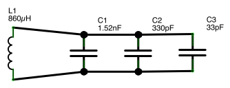
This LC circuit does not resonate exactly at 125kHz but at 125.068kHz:
f = 1/(2π √(860 x 10^-6) x (1.883 x 10^-9)) = 125.068kHz
This 68Hz difference is not that significant since the reader actually sweeps a range of the frequency from a minimum and a maximum at equal distance from the main frequency i.e. 125kHz in this case.
Modulation
The EM4100 protocol uses PSK modulation to transmit information. A 1N4148 diode bridge is plugged on the LC circuit and an Arduino output pin in order to manipulate the inducted signal: when the Arduino pin is LOW, this corrects the induced signal, which is a “1” logic for the reader. When the pin is HIGH, the diode bridge is inert and does not alter the signal and is therefore a “0” logic.
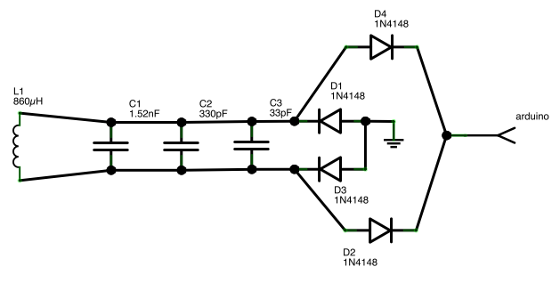
The EM4100 protocol uses 64, 32 or 16 cycles for the synchronisation between the reader and the transponder. One cycle last 8μs:
125kHz = 125 x 10^3 cycles / 1 second → 1/(125 x 10^3) = 8 x 10^-6 second per cycle
In this project, the clock period lasts 64 cycles, which means in seconds:
64 x (8 10^-6) = 512μs
The protocol uses the Manchester encoding that representing a value by a transition during the clock period. Therefore, for each value of the line code, during a half clock period (256 ), the Arduino pin will be HIGH or LOW then LOW or HIGH for another half clock period.
void spoofnow() {
  for(int i = 0; i < 64; i++) {
    send_manchester(0, spoofed_card[i]);
    delayMicroseconds(256);
    send_manchester(1, spoofed_card[i]);
    delayMicroseconds(256);
  }
}
Encoding
The Manchester encoding represents the “1” logic with a negative transition and the “0” logic with a positive transition. A negative transition means half a period of the clock, the signal is HIGH, the other half, the signal is LOW.
void send_manchester(int clock_half, int signal) {
  // XOR the clock and the signal
  int man_encoded = clock_half ^ signal;

  if(man_encoded) {
    digitalWrite(coil_pin, LOW);
  } else {
    digitalWrite(coil_pin, HIGH);
  }
}
EM4100 protocol
The EM4100 has a special data format for sending its unique ID (Priority 1 Design 2007). First, it starts with 9bit header of logic 1 followed by an 8bit version number (D00-07), then the 32 bits of the unique ID (D08-39) and finally it ends with a 4bit column parity and 1 stop bit (S0) represented by a 0 logic. The 9 bits are used to automatically synchronise the clock signal with the reader. Each group of 4 bits is actually followed by an even parity bit (P0-9).
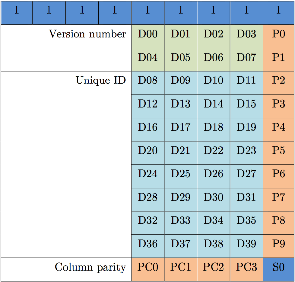
This means a transponder with version number 06 and a unique ID 00CAFE42 will send the following data:
111111111 0000 0 0110 0 0000 0 0000 0 1100 0 1010 0 1111 0 1110 1 0100 1 0010 1 0111 0
Summary
Here is a summary of how the RFID spoofer works:
- The user enters the unique ID to spoof
- The RFID spoofer generates the data to be sent in the proper format
- The data is encoded in Manchester
- The line code is outputted on the Arduino pin connected to the 125kHz antennamodule
Regarding the output, the antenna will rectify the induced signal (the electromagnetic field) which will be interpreted by the reader by as a 1 or a 0.
Source codes
Here are the source code for both the spoofer.
// Define the Arduino PIN
#define coil_pin 12

// ID to spoof
char data[10] = {'0', '6', '0', '0', 'C', 'A', 'F', 'E', '4', '2'};

int spoofed_card[64];

void setup() {
  Serial.begin(9600);
  pinMode(coil_pin, OUTPUT);
  digitalWrite(coil_pin, LOW);
  build_content();
}

void loop() {

  delay(500);
  Serial.println("Ready for spoofing");

  for(int h = 0; h < 50; h++)
    spoofnow();

  Serial.println("Spoof done");
}

// Function that build the transponder's content
void build_content() {

  // iterator for the ID wanted
  int data_iterator = 0;

  // hex value of the ID
  int raw_data;
  int i;

  // the 9 first bit are 1 logic (a+9)
  for (i = 0; i < 9; i++) {
    spoofed_card[i] = 1;
  }

  // the 5th bit is for parity. Calculated at the end
  // This loop writes each hex in bit
  for (int a = 0; a < 10; a++) {
    raw_data = HexToDec(data[data_iterator]);
    spoofed_card[(a*5)+9] = bitRead(raw_data, 3);
    spoofed_card[(a*5)+10] = bitRead(raw_data, 2);
    spoofed_card[(a*5)+11] = bitRead(raw_data, 1);
    spoofed_card[(a*5)+12] = bitRead(raw_data, 0);
    data_iterator++;
  }

  int bit_set = 0;

  // CRC ROW
  for(int r = 0; r < 10; r++) {
    // Calculate number of 1 per row
    for(i = 0; i < 4; i++) {
      if(spoofed_card[(r*5)+i+9]) {
        bit_set++;
      }
    }

    // If number of 1 is even, parity = 1 else 0
    if((bit_set % 2) != 0) {
      spoofed_card[(5*r)+4+9] = 1;
    } else {
      spoofed_card[(5*r)+4+9] = 0;
    }

    bit_set = 0;
  }

  // CRC COLUMN
  bit_set = 0;

  for(int c = 0; c < 4; c++) {

    // Calculate number of 1 per column
    for(i = 0; i < 10; i++) {

      if(spoofed_card[c+(i*5)+9]) {
        bit_set++;
      }
    }

    // If number of 1 is even, parity = 1 else 0
    if((bit_set % 2) != 0) {
      spoofed_card[50+9+c] = 1;
    } else {
      spoofed_card[50+9+c] = 0;
    }

    bit_set = 0;
  }

  // Last bit = stop bit = 0
  spoofed_card[63] = 0;
}

// Function that converts Hexadecimal in Decimal
int HexToDec(char hexa) {

  if(hexa == '0')
    return 0;

  if(hexa == '1')
    return 1;

  if(hexa == '2')
    return 2;

  if(hexa == '3')
    return 3;

  if(hexa == '4')
    return 4;

  if(hexa == '5')
    return 5;

  if(hexa == '6')
    return 6;

  if(hexa == '7')
    return 7;

  if(hexa == '8')
    return 8;

  if(hexa == '9')
    return 9;

  if(hexa == 'A')
    return 10;

  if(hexa == 'B')
    return 11;

  if(hexa == 'C')
    return 12;

  if(hexa == 'D')
    return 13;

  if(hexa == 'E')
    return 14;

  if(hexa == 'F')
    return 15;
}

void spoofnow() {
  for(int i = 0; i < 64; i++) {
    send_manchester(0, spoofed_card[i]);
    delayMicroseconds(256);
    send_manchester(1, spoofed_card[i]);
    delayMicroseconds(256);
  }
}

void send_manchester(int clock_half, int signal) {
  // XOR the clock and the signal
  int man_encoded = clock_half ^ signal;

  if(man_encoded) {
    digitalWrite(coil_pin, LOW);
  } else {
    digitalWrite(coil_pin, HIGH);
  }
}
ProxClone - Card Spoofer
Spoofing Definition
"To communicate electronically under a false identity"
"A type of deception where an intruder attempts to gain access to a user’s system or information via pretending to be the user."
My Card Spoofer Project
After spending many hours reverse engineering the bit streams from various card readers I felt that I had a pretty clear picture of the basic formats that were being used by the access card vendors whose cards I was testing. It was now time to build an equivalant electronic device that could emulate any of these 125Khz cards.
Below is a photo showing two different versions of my proximity card spoofer.
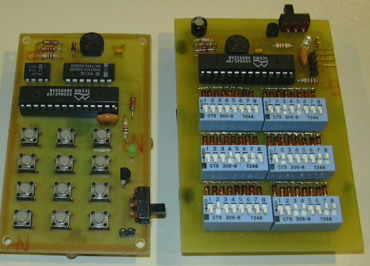
Each of the two designs share a common capability; That is, the ability to generate an FSK bit stream that is used to shunt (short) the LC tuned circuit which is receiving the 125 Khz carrier from the card reader. The spoofer on the left uses an analog switch to short the LC circuit whereas the circuit on the right simply uses a GPIO output of the microcontroller to drive the rectified LC input to a Logic 0 (ground) state.
The two versions also differ in how the "spoofed" card data is input. The unit on the left allows a user to key in the card parameters (facility code, card number and bit length/format. The microcontroller firmware then calculates the appropriate header and parity bits before sending out the modulated card data to the reader.
The spoofer on the right gives the user the most flexibility by allowing all transmitted bits of information to be selected via DIP switches. This approach provides the most flexibility and is more universal but it also requires the user to have more knowledge about the specific details of the card that is being spoofed.
A schematic diagram for the spoofer on the right is shown below. Both of the designs use a single-sided PWB that I etched myself. The total parts cost was less than $15.

he 125 Khz carrier signal is received by the tuned LC antenna circuit where it is full wave rectified before being received by the microcontroller. The microcontroller uses an internal analog comparator to look at the rectified signal to determine if it is in the vicinity of a reader. If the signal is at least 1 Volt or greater it begins to backscatter modulate the FSK card data by shunting the LC tuned circuit using the FSK timing as shown below. A 5V zener diode is used to protect the microcontroller from any high voltage signals that may be present.
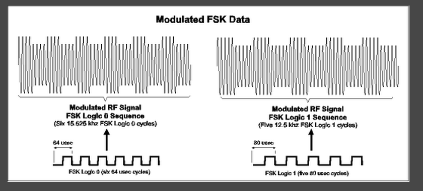
Note: The above FSK data does not reflect the manchester encoding that is done to the final data stream. That is, a manchester encoded output for a Logic 0 card bit consists of a FSK Logic 0 sequence plus a FSK Logic 1 sequence. A "Logic 1" card bit is sent out as a FSK Logic 1 sequence plus an FSK Logic 0 sequence. (Confused yet?)
The above spoofers have been extensively tested in the field and have been able to fool numerous RFID access systems by emulating various 26-bit, 34-bit, 35-bit (Corporate 1000), 36-bit and 37-bit systems. They can also be used in conjunction with my reader/cloner to create a clone card that can be programmed with any facility code, card number, and format. It's kind of like a "Skeleton Key" for 125 Khz proximity card systems.

We have known that the cheaper RFID technologies were pretty insecure for a number of years. Researchers have demonstrated cloners of all varieties, but simple RFID tags are still being used for access control. Even my current employer uses them.
A while ago, I was looking at Hack A Day, and I saw an amazing project that somebody had made. It was an RFID card with a keypad on it. For the next couple of days, I couldn't get the image of the card out of my mind; the project reminded me of how much I wanted to build a RFID spoofer myself. The original author didn't release source code for their project, but they left enough clues that I could follow.
So, in typical fashion, I built my own reader hardware so I could have a look at the data from a card, and created my own version of the Universal RFID key.
The key I made works beautifully both on my garage door, as well as a number of other RFID readers I have tried!
I have decided to publish this, as more people should be aware of the design flaws that are inherent in older RFID implementations, and to allow others to make their own universal key.
Will this key let you into anybodies RFID protected office? Yes it will, assuming a couple of things are true
1) The have to be using 125kHz RFID tags that use the same encoding standard as I have designed this project for, and,
2) You have to have access to the number printed on the back of the tag - with that number, you can simply key it into the Universal RFID key, and it will emulate that tag.
So there you go - I hope you enjoy making this project. - And remember, with great power comes great responsibility!
Step 1: How does RFID work?
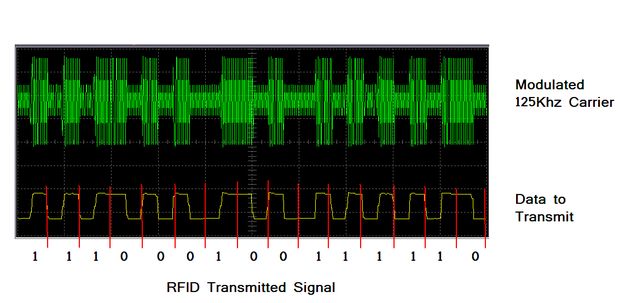
RFID, or Radio Frequency IDentification is the term used to describe a wide variety of standards that allow data stored within electronic 'tags' to be read by a reader without using wires. There are a number of standards, encoding formats, and frequencies in common use. I will describe the 125 kHz standard that is common for access control mechanisms.
125 kHz RFID tags are commonly encased in a business card sized piece of plastic, or a round disk. The tag consists of a coil of wire, connected to a microchip. When the tag is brought into close proximity to a reader, energy is coupled inductively from the reader to the microchip within the tag.
The energy from the reader has dual use; firstly, it provides power to run the card, and secondly, it provides a communication medium for data to be transmitted. Once powered up, the tag modulates the bit pattern that is programmed into the tag using a signal that the reader can detect. The reader then reads this bit pattern, and passes it onto the door controller. If the bit pattern matches one that is authorised, the door will be unlocked. If the bit pattern does not match an authorised one, then the door won't unlock.
In the RFID system I was playing with, the bit pattern looked like this;
1111111110010111000000000000001111100010111110111101001111010000
I will describe what this pattern actually means in the next page.
One interesting feature of the data transfer between the card and the reader, is that data is encoded using Manchester Encoding, which is a way of encoding data so that it can be transmitted over a single wire ensuring that the clock information is able to be recovered easily. With Manchester encoding, there is always a transition in the middle of a bit. If you want to transmit a 1, the transition would be from low to high, and if you want to transmit a 0, the transition would from from high to low. Because the transitions are in the middle of each bit, you can ensure that you have locked onto valid data. For a detailed description, have a look a this page.
The actual data is transmitted by the card effectively shorting the coil out - this applies an additional load to the transmitter in the reader, which can be detected.
Step 2: Whats stored on the card?

I started by building a RFID card reader (more details in a future article). That showed me the data that was being sent when the card transmitted its information.
The RFID cards that I brought have numbers printed on the back of them. This number says what data the card has included in it.
the card with 0007820706 119,21922 printed on it transmits this pattern:
1111111110010111000000000000001111011110101001010101000010101100
The first set of 111111111 bits are the start sequence - it is used to tell the reader that a code is coming - the reader also uses the sequence to lock onto the card data.
Data stored is transmitted in groups of 4 bits, with a parity bit at the end of every group.
The data can be broken up as follows;
00101 11000 00000 00000 01111 01111 01010 01010 10100 00101 0110 0
If we ignore the parity bit at the end of every nibble we have
0010 1100 0000 0000 0111 0111 0101 0101 1010 0010 0110 0
2 C 0 0 7 7 5 5 A 2 CHECKSUM STOP
This code is 2c 0077 55a2 if we break the code into 3 groups, we have 2c, followed by 0077 (which is 119 in decimal), and finally 55A2, which is 21922 in decimal - this corresponds to the 119,21922.
The same number is also written in another way on these cards 0007820706 (in decimal) is simply the hexadecimal number 7755A2.
WOOT we now understand how the data is stored.
2C is a constant code that is sent with all of the cards. It is simply a facility identifier for this RFID system.
How does the parity and checksum work?
One final piece of data that the card transmits is a checksum word - this is used to ensure that all of the data has been received successfully. Firstly, the parity bit at the end of each nibble of data is Even parity - this means that the transmitter will add a 1 to make sure that each block of data has an 'even' number of '1' bits - So if we look a the '2', which is 0010 in binary - the parity system would detect that there was an odd number of '1' bits, and would add one to compensate. Compare that to the 'C' which is 1100, the parity system would detect that there are an even number of '1' bits, so it would add a zero.
00101 2
11000 C
00000 0
00000 0
01111 7
01111 7
01010 5
01010 5
10100 A
00101 2
0110 checksum + 0 stop bit
Finally, the checksum is an even parity bit applied to each of the vertical row bits. This way, there is a horizontal and vertical check of every bit sent - everything has to line up, or the reader will simply reject the transmission.
When I decoded the data for my work prox card, it followed a similar sequence here, but (for obvious reasons) I won't actually publish the numbers. Again, part of the sequence was a facility code, and the rest of the sequence held the same number that was printed on the back of the card.
Step 3: How do we emulate a card?
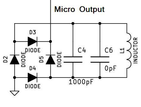
Modulation
The EM4100 protocol uses PSK modulation to transmit information.
A 1N4148 diode bridge is plugged on the LC circuit and an Arduino output pin in order to manipulate the inducted signal:
when the Arduino pin is LOW, this corrects the induced signal, which is a “1” logic for the reader.
When the pin is HIGH, the diode bridge is inert and does not alter the signal and is therefore a “0” logic.
So the next step was to identify how to pretend to be a card - I wanted a card that I could type a card number into,
so it had to have a microprocessor on it, was well as a keypad to allow the data to be keyed in.
The ATMega manipulates the 125kHz RF field by using a bridge rectifier.
When the output of the micro is low, the diodes in the bridge are allowed to be turned on by the current induced in the coil, this effectively short it out.
The reader detects the additional load, and a bit transition is detected.
The job of the micro is simply to turn the output on and off in a way that makes sense to our reader.
So I created a board that had the micro, a power supply, keypad, and some status LEDs on it.
The attached PDF is the full schematic of the project.
You may notice that c6 is 0pF - That is intentional c6 is a placeholder component allowing me to either use a 1000pF surface mount cap, or a 1000pF through hole cap.
The coil is 100 turns of fine wire would on an open former that is just smaller than the card border.
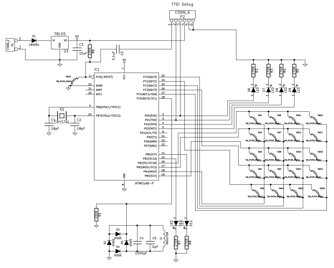
Step 4: The Software - Entering data into our card
One problem I came across, was when I was calculating the card data (parity and checksum) on the fly -
When the card is powered up, it waits for the 'mode' button to be pressed.
MODE 1 - Enter low power (sleep) mode
The card enters a low power mode, waiting for the reset button to be pressed to re-awaken it
MODE 2 - Enter a Hex Facility ID
The card waits for 2 digits to be entered signifying the facility code for this system (In this case, it is 2C) - The software defaults to 2C - so this does not need to be entered.
MODE 3 - Decimal Card ID
The card waits for 8 digits to be entered signifying the CardID for the card to be spoofed (In this case, it is 07820706) - This is the long number printed on the back of the card, not the 119,21922 number.
MODE 4 - Dump the facility and Card ID
The Facility and Card ID are Dumped as Hex numbers using the 4 Leds at the top of the card.
MODE 5 - Emulate a card
The card enters emulation mode - all LEDs are turned off.
The software relies on Mark Stanley's and Alexander Brevig's Keypad Library
#include <Keypad.h>
#include <stdio.h>
#include <EEPROM.h>
#include <avr/interrupt.h>
#include <avr/io.h>
#include <avr/sleep.h>

// uncomment the following line to get debug information dumped
#define SERIALDEBUG


/***************************************************************************
 *                                                                         *
 *  A Universal RFID Key - Instructables Version                           *
 *                                                                         *
 *   Copyright (C) 2010  Doug Jackson (doug@doughq.com)                    *
 *                                                                         *
 ***************************************************************************
 *                                                                         *
 * This program is free software; you can redistribute it and/or modify    *
 * it under the terms of the GNU General Public License as published by    *
 * the Free Software Foundation; either version 2 of the License, or       *
 * (at your option) any later version.                                     *
 *                                                                         *
 * This program is distributed in the hope that it will be useful,         *
 * but WITHOUT ANY WARRANTY; without even the implied warranty of          *
 * MERCHANTABILITY or FITNESS FOR A PARTICULAR PURPOSE.  See the           *
 * GNU General Public License for more details.                            *
 *                                                                         *
 * You should have received a copy of the GNU General Public License       *
 * along with this program; if not, write to the Free Software             *
 * Foundation, Inc., 59 Temple Place, Suite 330, Boston,                   *
 * MA  02111-1307  USA                                                     *
 *                                                                         *
 ***************************************************************************
 *                                                                         *
 *    * * * * * * * *      W A R N I N G     * * * * * * * * * *           *
 * This project implements what is effectively a universal skeleton key    *
 * for use on a range of RFID access systems.  It is presented for         *
 * educational and demonstration purposes only to enable others to learn   *
 * about the design and limitations of RFID technologies.                  *
 *                                                                         *
 * The Author is not responsible for misuse of the technological system    *
 * implemented by this software - USE AT YOUR OWN RISK!!                   *
 *                                                                         *
 ***************************************************************************
 *
 *
 * Revision History
 *
 * Date      By    What
 * 20101002    DRJ    Initial Creation of Arduino Version
 * 20101024     DRJ     Added facility to arbitrarily enter a facility and
 *                      UserID number
 * 20101025     DRJ     Added ability to enter decimal UserID
 * 20101124     DRJ     Removed my Work specific functions for public release
 ***************************************************************************
 *
 *  COMMAND STRUCTURE
 *
 * Mode key is pressed until appropriate mode is displayed on 4 upper leds
 * Enter key triggers action
 *
 * Mode 1 - Sleep (power down till next reset)
 * Mode 2 - Allow HEX facility code to be entered
 *          2 decimal characters are then read into facility[] array;
 * Mode 3 - Allow Decimal userID to be entered
 *          8 decimal characters are then read into user[] array;
 * Mode 4 - Dump data - Facility code and User code are output on 4 LEDs one byte at a time
 * Mode 5 - Emulate Card
 *
 *
 *************************************************************************************/

#define DATALED1 0
#define DATALED2 1
#define DATALED3 2
#define DATALED4 3
#define STATUSLED1 8
#define STATUSLED2 9

// the Coil is connected to Analog 5 = Digital 19
#define COIL 19


const byte ROWS = 5; //five rows
const byte COLS = 4; //four columns
char keys[ROWS][COLS] = {
  {
    '1','2','3','A'                  }
  ,
  {
    '4','5','6','B'                  }
  ,
  {
    '7','8','9','C'                  }
  ,
  {
    '*','0','#','D'                  }
  ,
  {
    'N','M','F','E'                  }
  ,

};
byte rowPins[ROWS] = {
  10, 11, 13, 17, 15}; //connect to the row pinouts of the keypad
byte colPins[COLS] = {
  12, 14, 16, 18}; //connect to the column pinouts of the keypad

byte facility[2]={ 0x02, 0x0C };
byte cardID[8]={ 0x00, 0x00, 0x00, 0x00, 0x00, 0x00, 0x00, 0x00 };
int colsum[4]={ 0,0,0,0}; // storage for the column checksums

// delay between symbols when we are transmitting
int bittime=256;

byte RFIDdata[128];


Keypad keypad = Keypad( makeKeymap(keys), rowPins, colPins, ROWS, COLS );

int clock=0;  // storage for the current state of our clock signal.

byte datapointer=0;
byte state;
byte mode=1;


void setup()
{

  pinMode(DATALED1, OUTPUT);
  pinMode(DATALED2, OUTPUT);
  pinMode(DATALED3, OUTPUT);
  pinMode(DATALED4, OUTPUT);
  pinMode(STATUSLED1, OUTPUT);
  pinMode(STATUSLED2, OUTPUT);


  pinMode(COIL, OUTPUT);
  //Start with it LOW
  digitalWrite(COIL, LOW);

  if (EEPROM.read(0)==0xa5)
  {
      facility[0]=EEPROM.read(1);
      facility[1]=EEPROM.read(2);

      cardID[0]=EEPROM.read(3);
      cardID[1]=EEPROM.read(4);
      cardID[2]=EEPROM.read(5);
      cardID[3]=EEPROM.read(6);
      cardID[4]=EEPROM.read(7);
      cardID[5]=EEPROM.read(8);
      cardID[6]=EEPROM.read(9);
      cardID[7]=EEPROM.read(10);
  }
  else
 {
    EEPROM.write(0,0xa5);
    facility[0]=0x02; EEPROM.write(1,facility[0]);
    facility[1]=0x0c; EEPROM.write(2,facility[1]);
      for (int i=0; i<8; i++)
    {
      cardID[i]=0; EEPROM.write(i+2,cardID[i]);
    }
  }


    #ifdef SERIALDEBUG
    Serial.begin(9600);
    delay(200);
    Serial.println("  ");
    Serial.println("RFID Spoofer (c) 2010 D Jackson");
    #endif
}

void WriteHeader(void)
{
  // a header consists of 9 one bits
  RFIDdata[datapointer++]=1;
  RFIDdata[datapointer++]=1;
  RFIDdata[datapointer++]=1;
  RFIDdata[datapointer++]=1;
  RFIDdata[datapointer++]=1;
  RFIDdata[datapointer++]=1;
  RFIDdata[datapointer++]=1;
  RFIDdata[datapointer++]=1;
  RFIDdata[datapointer++]=1;
}


void WriteData(byte nibble)
{
  byte data;
  byte rowsum=0;
  for (int i=4; i>0; i--)
  {
    if ((nibble& 1<<i-1) ==0)
    {
      data=0;
    }
    else
    {
      data=1;
      rowsum++;  // increment the checksum value
      colsum[i-1]++; // increment the column checksum
    }


    RFIDdata[datapointer++]= data;
    #ifdef SERIALDEBUG
      Serial.print((int) data);
    #endif

  }
  // write the row checksum out
  if ((rowsum%2)==0)
  {
    RFIDdata[datapointer++]=0;
    #ifdef SERIALDEBUG
      Serial.print((int)0);
    #endif

  }
  else
  {
    RFIDdata[datapointer++]=1;
    #ifdef SERIALDEBUG
      Serial.print((int)1);
    #endif
  }

    #ifdef SERIALDEBUG
      Serial.println();
    #endif

}


void WriteChecksum(void)
{
  byte data;
  byte rowsum=0;
  for (int i=4; i>0; i--)
  {
    if ((colsum[i-1]%2) ==0)
    {
      RFIDdata[datapointer++]=0;
     #ifdef SERIALDEBUG
      Serial.print((int)0);
     #endif
    }
    else
    {
      RFIDdata[datapointer++]=1;
      #ifdef SERIALDEBUG
      Serial.print((int) 1);
      #endif
    }
  }

  // write the stop bit
  RFIDdata[datapointer++]=0;

      #ifdef SERIALDEBUG
      Serial.print((int)0);
      #endif

}

void BuildCard(void)
{
  // load up the RFID array with card data
  // intitalise the write pointer
  datapointer=0;

  WriteHeader();
  // Write facility
  WriteData(facility[0]);
  WriteData(facility[1]);

  // Write cardID
  WriteData(cardID[0]);
  WriteData(cardID[1]);
  WriteData(cardID[2]);
  WriteData(cardID[3]);
  WriteData(cardID[4]);
  WriteData(cardID[5]);
  WriteData(cardID[6]);
  WriteData(cardID[7]);

  WriteChecksum();
}


void TransmitManchester(int cycle, int data)
{
  if(cycle ^ data == 1)
  {
    digitalWrite(COIL, HIGH); // COIL = HIGH : the diode brideg is insert and does not alter the signal and is therefore a '0' logic
  }
  else
  {
    digitalWrite(COIL, LOW); // COIL = LOW : this corrects the induced signal, which is a '1' logic  for the reader.
  }
}

void writedataLEDS(int temp)
{
  if (temp & 1<<0) digitalWrite(DATALED1,HIGH);
  else digitalWrite(DATALED1,LOW);
  if (temp & 1<<1) digitalWrite(DATALED2,HIGH);
  else digitalWrite(DATALED2,LOW);
  if (temp & 1<<2) digitalWrite(DATALED3,HIGH);
  else digitalWrite(DATALED3,LOW);
  if (temp & 1<<3) digitalWrite(DATALED4,HIGH);
  else digitalWrite(DATALED4,LOW);

}


void EmulateCard(void)
{
  #ifdef SERIALDEBUG
  Serial.println("Emulate Card Entered");
  #endif  // enter a low power modewritedataLEDS(0);  // turn off the LEDs

  BuildCard();

  #ifdef SERIALDEBUG
  Serial.println();
  for(int i = 0; i < 64; i++)
  {
    if (RFIDdata[i]==1) Serial.print("1");
    else if (RFIDdata[i]==0) Serial.print("0");
    else Serial.print((int)RFIDdata[i]);
  }
  Serial.println();
  #endif


  while (1==1)
  {
    for(int i = 0; i < 64; i++)
    {
      TransmitManchester(0, RFIDdata[i]);
      delayMicroseconds(bittime);
      TransmitManchester(1, RFIDdata[i]);
      delayMicroseconds(bittime);
    }
  }
}

void PowerDown(void)
{
  #ifdef SERIALDEBUG
  Serial.println("Sleep Mode Entered");
  #endif  // enter a low power mode

  writedataLEDS(0);  // turn off the LEDs

  set_sleep_mode(SLEEP_MODE_PWR_DOWN);
  sleep_enable();
  sleep_mode();
}


void DumpData(void)
{
  #ifdef SERIALDEBUG
  Serial.println("Dump Data Entered");
  #endif

  // dump the facility and card codes.
  writedataLEDS(0);  // turn off the data LEDs
  for (int i=0; i<2; i++)
  {
    digitalWrite(STATUSLED1,HIGH);
    writedataLEDS(facility[i]);
    delay(2000);
    digitalWrite(STATUSLED1,LOW);
    delay(500);
  }
  writedataLEDS(0);  // turn off the data LEDs
  digitalWrite(STATUSLED1,LOW);

  for (int i=0; i<8; i++)
  {
    digitalWrite(STATUSLED2,HIGH);
    writedataLEDS(cardID[i]);
    delay(2000);
    digitalWrite(STATUSLED2,LOW);
    delay(500);
  }
  digitalWrite(STATUSLED2,LOW);
  writedataLEDS(mode);
}


void LoadFacility(void)
{
  char key;
  byte temp;

  #ifdef SERIALDEBUG
  Serial.println("LoadFacility Entered");
  #endif

  writedataLEDS(0);  // turn off the data LEDs
  for (int i=0; i<2; i++)
  {
    writedataLEDS(facility[i]);
    // wait for a keypress
    key = NO_KEY;
    while (key == NO_KEY){
      delay(50);
      key = keypad.getKey();
    }
    switch (key){
      case '0': temp=0; break;
      case '1':  temp=1; break;
      case '2':  temp=2; break;
      case '3':  temp=3; break;
      case '4':  temp=4; break;
      case '5':  temp=5; break;
      case '6':  temp=6; break;
      case '7':  temp=7; break;
      case '8':  temp=8; break;
      case '9':  temp=9; break;
      case 'A':  temp=0x0a; break;
      case 'B':  temp=0x0b; break;
      case 'C':  temp=0x0c; break;
      case 'D':  temp=0x0d; break;
      case 'E':  temp=0x0e; break;
      case 'F':  temp=0x0f; break;
    }

    digitalWrite(STATUSLED1,HIGH);
    facility[i]=temp;

    writedataLEDS(facility[i]);
    delay(200);
    writedataLEDS(0);
    delay(200);
    writedataLEDS(facility[i]);
    delay(200);
  }

  writedataLEDS(mode);
  digitalWrite(STATUSLED1,LOW);
  delay(100);
  digitalWrite(STATUSLED1,HIGH);
  for (int i=0; i<2; i++) EEPROM.write(i+1,facility[i]);
  delay(200);
  digitalWrite(STATUSLED1,LOW);
}


void LoadCardID(void){
  char tempchar[9];  // temporary storage for decimal to int conversion
  char key;
  byte temp;
  long decimalval;

  #ifdef SERIALDEBUG
  Serial.println("LoadDecimalCardID Entered");
  #endif

  writedataLEDS(0);  // turn off the data LEDs
  for (int i=0; i<8; i++)
  {
    // wait for a keypress
    key = NO_KEY;
    while (key == NO_KEY){
      delay(50);
      key = keypad.getKey();
    }

    tempchar[i]=key;

    digitalWrite(STATUSLED2,HIGH);

    writedataLEDS(tempchar[i]);
    delay(200);
  }

  tempchar[8]='\n';
  #ifdef SERIALDEBUG
    Serial.print("datastring="); Serial.println(tempchar);
  #endif
  decimalval=atol(tempchar);
  #ifdef SERIALDEBUG
   Serial.print("datalong="); Serial.println((unsigned long)decimalval);
  #endif

  sprintf(tempchar,"%4.4X",(decimalval & 0xffff));
  #ifdef SERIALDEBUG
   Serial.print("dataHEXLO=");
   Serial.println(tempchar);
  #endif
  for (int i=4; i<8; i++) cardID[i]=asciitohex(tempchar[i-4]);

  decimalval = ((decimalval & 0xffff0000) >> 16);
  sprintf(tempchar,"%4.4X",decimalval);
  #ifdef SERIALDEBUG
   Serial.print("dataHEXHi=");
   Serial.print(tempchar);
  #endif
  for (int i=0; i<4; i++) cardID[i]=asciitohex(tempchar[i]);

  writedataLEDS(mode);
  digitalWrite(STATUSLED2,LOW);
  delay(100);
  digitalWrite(STATUSLED2,HIGH);
  for (int i=0; i<8; i++) EEPROM.write(i+3,cardID[i]);
  delay(200);
  digitalWrite(STATUSLED2,LOW);
}


char asciitohex(char value)  {
    char temp;
    switch (value){
      case '0':  temp=0; break;
      case '1':  temp=1; break;
      case '2':  temp=2; break;
      case '3':  temp=3; break;
      case '4':  temp=4; break;
      case '5':  temp=5; break;
      case '6':  temp=6; break;
      case '7':  temp=7; break;
      case '8':  temp=8; break;
      case '9':  temp=9; break;
      case 'A':  temp=0x0a; break;
      case 'B':  temp=0x0b; break;
      case 'C':  temp=0x0c; break;
      case 'D':  temp=0x0d; break;
      case 'E':  temp=0x0e; break;
      case 'F':  temp=0x0f; break;
    }
   return temp;
}

void loop(void)
{
  char key = keypad.getKey();

  if (key != NO_KEY){

    if (key=='M') {
      mode++;
      if (mode>5) mode=1;
      writedataLEDS(mode);
      delay(100);
      Serial.print("Mode=");
      Serial.println((int)mode);
    }

    if (key=='N')  {   // enter key pressed - dofunction
      switch (mode){
      case 1:
        PowerDown();    // power down mode
        break;
      case 2:
        LoadFacility(); // allow user to enter facility data
        break;
      case 3:
        LoadCardID();   // allow user to enter the card id
        break;
      case 4:
        DumpData();     // display the card data
        break;
      case 5:
        EmulateCard();  // start card emulation
        break;
      }
      #ifdef SERIALDEBUG
       Serial.println(key);
      #endif
    }
  }
}
Step 9: Further steps
You are welcome to adapt the project however you would like to, and while you may have the skeleton keys to the kingdom, you still need the little numbers on the back of the access card before you can use the key yourself.
I have considered modifying my card so that it works as all of the compatible RFID tags that I hold. In my job, I need have access to multiple work sites, and it would be great to use the one card, but I don't think that would be a great idea..........
Will this work on all RFID sytems?
No it won't. This is a good thing.
The first RFID systems deployed years ago used very simple protocols, based on the intelligence of the chip in the card - They also used a low frequency (125kHz) carrier.
More modern systems use a number of techniques to ensure security, such as one time codes; cryptography; use bi-directional communication; use internal passwords, and use much higher frequencies. So spoofing these systems is a lot more work.
But there are a large number of low tech systems in place now.
What can I do to protect my system?
Firstly, don't equate cards to physical keys - in simple systems they are not equivalent.
Don't give out visitor cards - They are easily duplicated - I f you do need Visitor cards, then implement a system where they are only active when they have been issued.
Enable Pass Back systems - If the card system believes you are in a particular room, make sure that the card can't be used in other rooms at the same time.
Remove the numbers from the back of the cards - while they may make it easier to enter card details, but they also make it easy for somebody to use the details for their own purposes.
Finally, look at how to upgrade your access system to a card system that is not trivially spoofed using $15 worth of parts. And - No, purchasing a new system from eBay for $15 is not the answer....
Scheme emulator RFID-tag
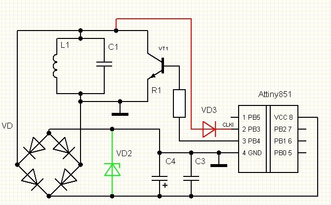
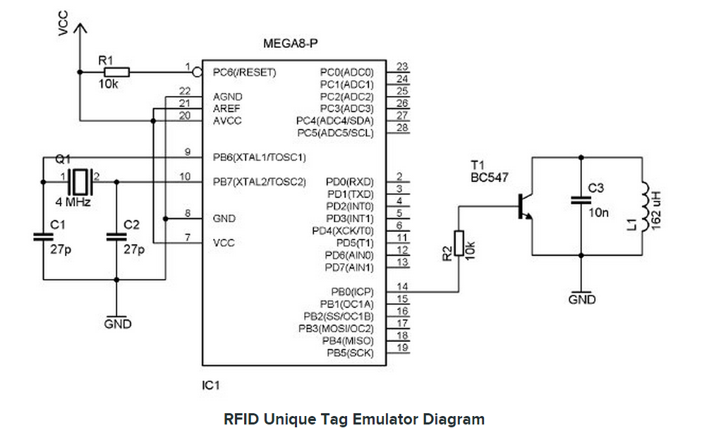

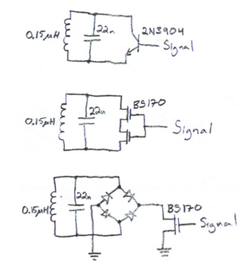
/* Basic schematic:
 *
 *              ATtiny85
 *              +--------------+
 *            --| RST      Vcc |--
 *    +- L1 ----| B3/CLKI  SCK |--
 *    +---------| B4      MISO |--
 *            --| GND     MOSI |--
 *              +--------------+
 *
 * L1 is about 1 mH. It and the AVR are the only components.
 * All other pins should be unconnected.
 */
http://svn.navi.cx/misc/trunk/avrfid/avrfid.S
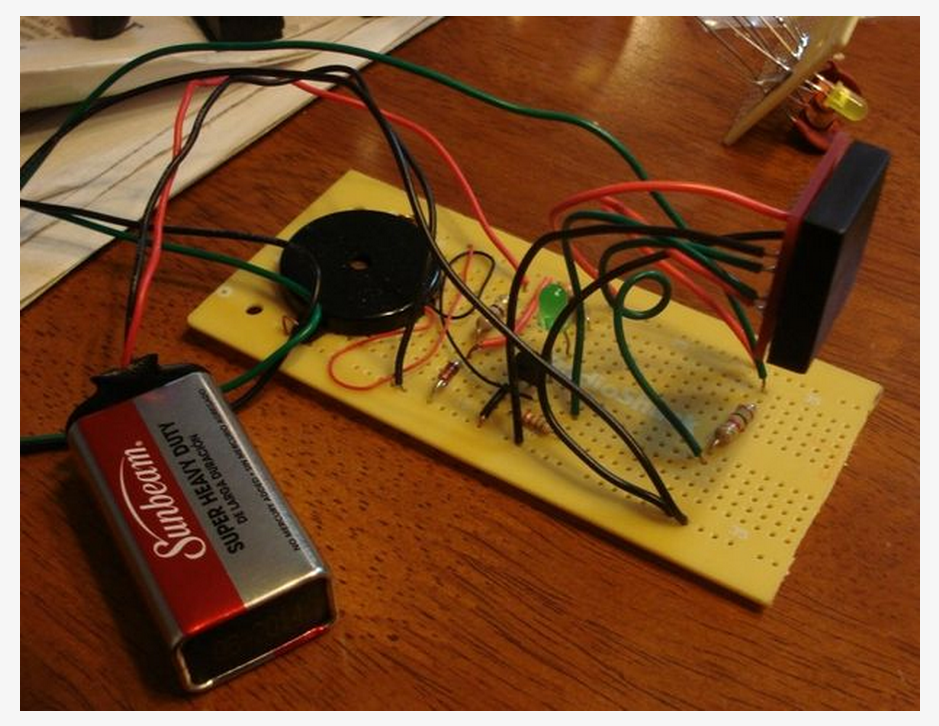
There is a lot of buzz lately about RFID (Radio Frequency ID) tags, mostly because of JC Penny's announcement of switching their retail system to RFID. Some of the buzz contains horror scenes like a hacker driving past your house and scanning it to inventory what you own. Or imagine your "Doggie Door" being hacked and you wake up with a pack of dogs in your kitchen eating food out of your RFID enabled refrigerator.
I decided to get more facts firsthand. So I ordered RFID components from Spark Fun Electronics (www.sparkfun.com/8419) and built my own RFID reader, pictured here. It works great but not nearly good enough to do the bad things described by RFID critics.
But then I came across an Instructable that described building a RFID DETECTOR (www.instructable.com/id/RFID-Reader-Dectector-and-Tilt-Sensitive-RFID-Tag/). It looked easy enough and so I built a similar one that I modified to work with my RFID reader.
This Instructable describes how to build a RFID Dectector that works...
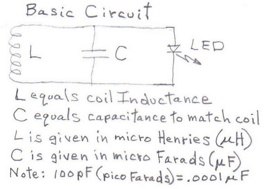
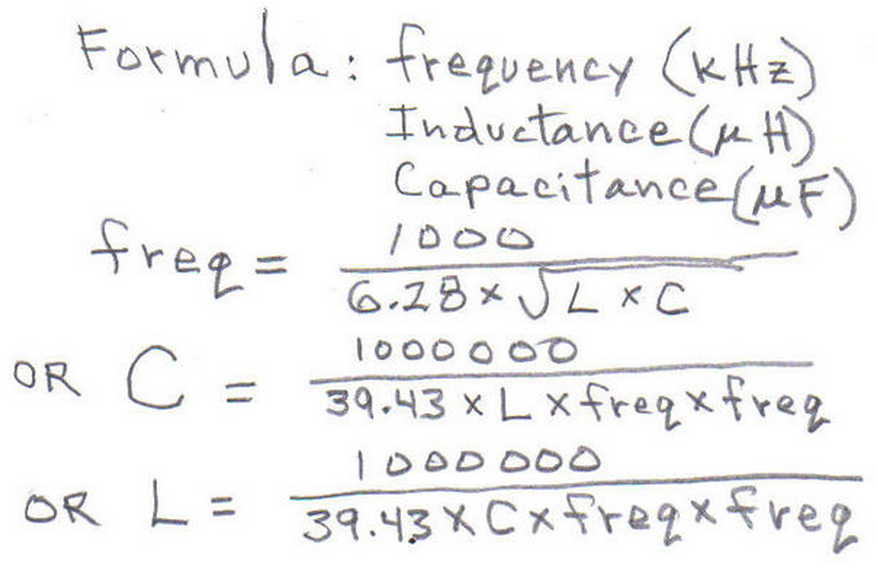


Part List:
About 40 feet of thin wire, 22 to 30 gage - I used 30 gage - Radio Shack
One common LED - I liked the red LED - Radio Shack
One .005 uF capacitor OR two .01 uF disk capacitors hooked up in series- Radio Shack
Two to five 100 pF disc capacitors - Radio Shack
Any kind of form or holder that allows one to wind a four inch diameter coil
Radio Shack type of breadboard or "prototype board" - (allows trial and error)
Some kind of circuit board for neatness but simple direct wiring could be used
Access to an RFID reader to allow testing of detector
No batteries required as this Detector gets its power wirelessly from the RFID reader (heh-heh)
When I finished winding my coil, I compared it with other coils I had and determined the inductance of my newly wound coil to be about 330 uH - (I had hoped for a much higher value).
I plugged 330 uH into the formula above and the result suggested that I needed a .005 uF capacitor to match my 330 uH coil so that the coil - capacitor combination would "resonate" at 125 kHz, allowing enough power to reach and light the LED.
Before doing any soldering, I connected all the parts to a plastic "breadboard," sometimes called a prototype board.
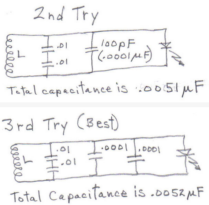
After breadboarding the coil, LED and two .01 uF capacitors hooked up in series and then hooked in parallel with the LED (to give a net capacitance of .005 uF (5000 pF), I powered up my little RFID reader and when I moved the coil within 4 inches of the reader, the LED started to glow. The LED glowed very brightly when I held the coil about one-half inch from the reader. I then add a 100 pF (.0001 uF) capacitor in parallel to the circuit.This further increased the range. And then I found that adding even another 100 pf capacitor (total of two 100 pF capacitors) in parallel with everything caused a further improvement in range. But adding a third 100 pf capacitor decreased the range. So with my coil, it looked like 5200 pf of capacitance was best for the coil that I had (see 3rd Try schematic).
My detector would have worked if I had simply wired up a capacitance of .005 uF in parallel with the coil and LED but the breadboard along with a few extra capacitors allowed me to make the detector reach up to five inches rather than just four inches. This is why a breadboard and some extra capacitors might be helpful for matching the coil that you wind.
The sequence of pictures here reveals how the LED goes from not being visible to brighter and brighter as the coil is placed closer to the RFID reader.
So this little device works - for 125 kHz ("kilo Hertz") readers. It's easy to make and somewhat forgiving even if the parts are not "exact" or "ideal."
I then soldered the parts used on the breadboard onto a piece of Radio Shack project board. However, the parts could have been just wired together "ugly style" and then soldered. This would have worked. I then taped the little circuit board to the coil so that the whole unit, coil and all could be handheld, free of any other wires or connections. This handheld unit worked just fine. I would expect it to detect any RFID Reader as long as the Dectector was within 3 to 5 inches of the reader AND the reader operated at a frequency of 125 kHz.
Since I now knew that the capacitance that gave me the most light at a given distance was .0052 uF, I plugged this value along with 125 kHz into the appropriate formula and got an Inductor value of 312 uH instead of the 330 uH value I thought I had. The math here might not be absolutely necessary but it helped me predict what capacitor value might best match my guessed inductance of the wound coil. Using only trial an error might have worked but this would have required more capacitors on hand and very likely more "trial and error."
Furthermore, the principles revealed by the general schematic and the related formulas apply to many RFID situations as well as situations related to metal detectors and radio receivers and transmitters. But that's another story...
http://youtu.be/aVBAZ8GvboQ
And now I've decided to finish here by attempting to add access to a video that reveals the action of the RFID Reader Detector...
RFID sniffer
About this project
RFID is everywhere.
Use the easy to build RFID sniffer to find out if objects are tagged.
The RFID sniffer is a simple analog electronic circuit which can detect the presence of 13.56 MHz RFID tags.
These tags are commonly used in all kinds of plastic cards like access badges,
bank cards, library cards, loyalty cards and so on.
Also many other objects may carry RFID tags without you knowing it.
Books, toys, and even clothing might be tagged.
Carrying tagged objects with you can reveal your identity or whereabouts to anyone equipped with the appropiate tools to read RFID tags.
The RFID sniffer helps you identify which objects are tagged, and which are not.
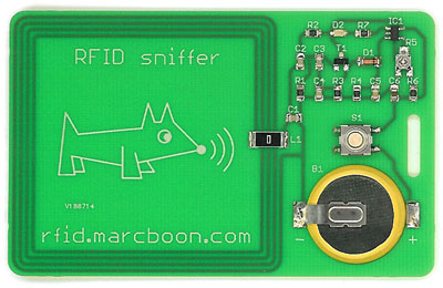
RFID sniffer
Wireless RFID Smart Key Detector Circuit
designed by David Johnson, P.E.
The hobby circuit below was designed to indicate if a key held over the small coil of wire contains a 125KHz RFID chip.
These chips are often used in smart car ignition keys.
The left side circuit forms a 125KHz power oscillator, which drives the 680uH air core inductor.
The magnetic field generated excites the RFID chip inside the key.
The AM signal produced by the key is stripped off of the 125KHz carrier, is filtered and is routed to the clock input of a flip/flop.
The flip/flop is configured as a one-shot pulse generator.
With the component values shown, the clock signal only has to be about 100 millivolts peak to peak to toggle the one-shot action.
If the flip/flop is toggled, a red LED is turned on.
Try about 250 turns of 30 gage magnet wire with a diameter of one inch for the air core coil.
Tune the electronic circuit for 125KHz by adjusting the value of the series 0.002uF cap.
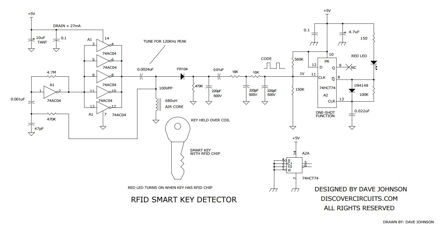

