增益 Gain 分贝 dB
https://zh.wikipedia.org/wiki/%E5%88%86%E8%B2%9D
分贝(decibel)是量度两个相同单位之数量比例的单位,主要用于度量声音强度,常用dB表示。
“分”(deci-)指十分之一,个位是“贝”或“贝尔”(bel),但一般只采用分贝。
分贝(dB)是十分之一贝尔(B): 1B = 10dB。
功率量
考虑功率或者强度(intensity)时, 其比值可以表示为分贝,这是通过把测量值与参考量值之比计算基于10的对数,再乘以10。
因此功率值P1与另一个功率值P0之比用分贝表示为LdB:
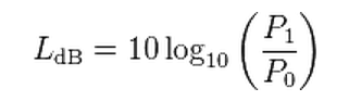
两个功率值的比值基于10的对数,就是贝尔(bel)值。
两个功率值之比的分贝值是贝尔值的10倍(或者说,1个分贝是十分之一贝尔)。
P1 与P0必须度量同一个数值类型,具有相同的单位。
如果在上式中P1 = P0,那么LdB = 0。
如果P1大于P0,那么LdB是正的;
如果P1小于P0,那么LdB是负的。
重新安排上式可得到计算P1的公式,依据P0与LdB:
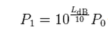
因为贝尔是10倍的分贝,对应的使用贝尔(LB)的公式为

所有例子都是无量纲的分贝表示的值,因为它们是同量纲的两个数量的比值的分贝表示。
"dBW"表示参考值是1瓦特,"dBm"表示参考值是1毫瓦。
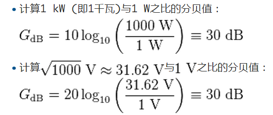
注意到 ,
,
解释了上述 的定义具有相同的值——
不论是用功率值还是电压幅值计算出来的,只要在特定系统中功率之比正比于幅值之比的平方。
使用分贝有很多便利之处:
- 分贝实际上是对数值,因此可以用常用的数量来表示非常大的比值,可以清楚地表示非常大的数量变化。
- 多部件系统的整体增益(如级联的放大器)可以直接用各部件的增益分贝相加而求得。
不必把这些增益值相乘(例如log(A × B × C) = log(A) + log(B) + log(C))。 - 人对强度的感知,如声音或者光照,更接近与强度的对数成正比而不是强度值本身,
依据韦伯定理,因此分贝值可用于描述感知级别或级差。
电子学中,通常用分贝表示功率或幅值之比(增益),而不常用算术比或者百分比。
一项好处是一些列部件组成的系统的总增益是各部件增益之和。
dB与后缀的组合,指出计算比值时的参考值。例如dBm指示功率值与1毫瓦的比值的分贝数。
如果计算分贝时的参考值明确、确切地给出,那么分贝数值可以作为绝对量,
如同被测量的功率量或者场量。例如,2 dBm即为10毫瓦。
由于分贝是依据功率而定义的,因此把电压比值转化为分贝,必须采用20倍对数。
在分贝计前大叫得震耳欲聋,可能也不如轻轻对准探测器一吹的分贝读数来得大。
这可能是因为尖叫只带来空气中能量的传送,但吹风带动空气粒子直接撞击分贝计的探测器,
引起额外的“零距离”声波,取得更大的正增长参数数值
增益
增益在电子学上,通常为一个系统的讯号输出与讯号输入的比率。
如5倍的增益,即是指系统令电压或功率增加了5倍。
增益主要应用于放大电路中。
对数单位与分贝
电子学上常使用对数单位量度增益,并以贝(bel)作为单位:
- Gain = log10(P2/P1) bel
其中P1与P2分别为输入及输出的功率。
由于增益的数值通常都很大,因此一般都使用分贝(dB,贝的10分之1)来表示:
- Gain = 10×log10(P2/P1) dB
一个类似的单位使用自然对数,称为neper。
当增益以电压而非功率计算时,使用焦耳定律 (Joule's law,P=V2/R),其公式为:
- 增益 =10×log10 ((V22/R) /(V12/R) )dB
=10×log10((V2/V1)2)dB
=20×log10(V2/V1) dB
此公式只有在负载阻抗相等(阻抗匹配)时才为正确。
在不少现代电子设备中,由于输出阻抗较低,而输入阻抗则较高,令负载可被忽略而不明显地影响计算结果。
举例
如一个放大器输出1伏特至1欧姆的负载,提供的输出功率为1瓦特。
如放大器被调节至输出10伏特至同一负载,它提供的输出功率则为100瓦特(P=V2/R)。
因此:电压增益 = 100/10 = 10倍
P = V²/R
功率增益 = (100²/R) / (10²/R) = 100倍
根据定义,其功率增益为 10Log100 = 20 dB
如果增益为1或0 dB,即输出电压等于输入电压,这个增益也称为单位增益。
功率增益(英语:Power gain)是指一个电路里输出功率和输入功率的比例。
不像其他的信号增益,例如电压增益和电流增益,功率增益由于“输入功率”和“输出功率”本身有着相对模糊的定义,因此有时显得有点混淆。
三种重要的功率增益包括:
- 运算功率增益(英语:operating power gain)、
- 转换功率增益(transducer power gain)和
- 有效功率增益(available power gain)。
值得注意的是,上述三种增益的定义均基于功率的平均效果,而非瞬时功率,不过“平均”二字经常被省略,在有的情况会引起混淆。
The amplification factor, also called gain , is the extent to which an analog amplifier boosts the strength of a signal .
Amplification factors are usually expressed in terms of power .
The decibel (dB), a logarithmic unit, is the most common way of quantifying the gain of an amplifier.
For power, If the output-to-input signal power ratio is 1:1, then the amplification factor is 0 dB.
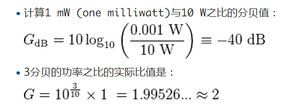
a doubling the signal strength (an output-to-input power ratio of 2:1) translates into a gain of 3 dB;
a tenfold increase in power (output-to-input ratio of 10:1) equals a gain of 10 dB;
a hundredfold increase in power (output-to-input ratio of 100:1) represents 20 dB gain.
If the output power is less than the input power, the amplification factor in decibels is negative.
Power amplifiers typically have gain figures from a few decibels up to about 20 dB.
Sensitive amplifiers used in wireless communications equipment can show gain of up to about 30 dB.
If higher gain is needed, amplifiers can be cascaded, that is, hooked up one after another.
But there is a limit to the amplification that can be attained this way.
When amplifiers are cascaded, the later circuits receive noise at their inputs along with the signals.
This noise can cause distortion.
Also, if the amplification factor is too high, the slightest feedback can trigger oscillation,
rendering an amplifier system inoperative.
Amplifier Gain & Decibels
Voltage Amplification
The Voltage Amplification (Av) or Gain of a voltage amplifier is given by:
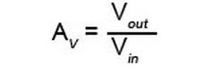
With both voltages measured in the same way (i.e. both RMS, both Peak, or both Peak to Peak),
Av is a ratio of how much bigger is the output than the input, and so has no units.
It is a basic measure of the Gain or effectiveness of the amplifier.
Because the output of an amplifier varies at different signal frequencies,
measurements of output power, or often voltage, which is easier to measure than power,
are plotted against frequency on a graph (response curve)
to show comparative output across the working frequency band of the amplifier.
Logarithmic Scales
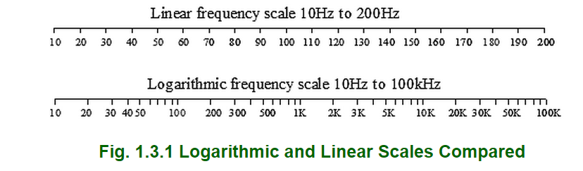
Response curves normally use a logarithmic scale of frequency, plotted along the horizontal x-axis.
This allows for a wider range of frequency to be accommodated than if a linear scale were used.
The vertical y-axis is marked in linear divisions but using the logarithmic units of decibels
allowing for a much greater range within the same distance.
The logarithmic unit used is the decibel, which is one tenth of a Bel,
a unit originally designed for measuring losses of telephone cables,
but as the Bel is generally too large for most electronic uses, the decibel (dB) is the unit of choice.
Apart from providing a more convenient scale the decibel has another advantage in displaying audio information,
the human ear also responds to the loudness of sounds in a manner similar to a logarithmic scale,
so using a decibel scale gives a more meaningful representation of audio levels.

Power Gain in dBs
To describe a change in output power over the whole frequency range of the amplifier,
a response curve, plotted in decibels is used to show variations in output.
The powers at various frequencies throughout the range are compared to
a particular reference frequency, (the mid band frequency).
The difference in power at the mid band frequency and the power at any other frequency being measured,
is given as so many decibels greater (+dB) or less (-dB) than the mid band frequency,
which is given a value of 0dB.
Notice that, on the logarithmic frequency scale in Fig 1.3.1 the middle of the 10Hz to 100kHz band is 1kHz
and frequencies around this figure (where the output is usually at its maximum)
are normally chosen as the reference frequency.
Converting a power gain ratio to dBs is calculated by multiplying the log of the ratio by 10:
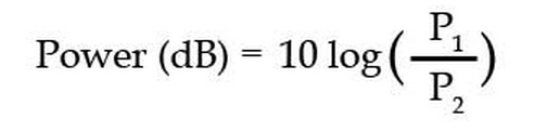
Where P1 is the power at mid band and P2 is the power being measured.
Note: When using this formula in a calculator the use of brackets is important,
so that 10 x the log of (P1/P2) is used, rather than 10 x the log of P1, divided by P2.
e.g. if P1 = 6 and P2 =3
10 x log(6/3) =3dB (right answer), but 10 x log 6/3 = 2.6dB (wrong answer).
Voltage Gain in dBs
Although it is common to describe the voltage gain of an amplifier as so many decibels,
this is not really an accurate use for the unit.
It is OK to use decibels to compare the output of an amplifier at different frequencies,
since all the measurements of output power or voltage are taken across the same impedance (the amplifier load),
but when describing the voltage gain (between input and output) of an amplifier,
the input and output voltages are being developed across quite different impedances.
However it is quite widely accepted to also describe voltage gain in decibels.
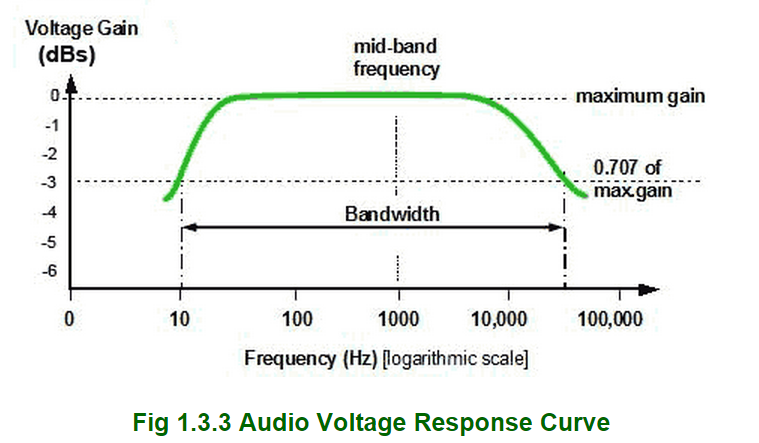
When voltage gain(Av) or current gain (Ai) is plotted against frequency the −3dB points are where the gain falls to 0.707 of the maximum (mid band) gain.
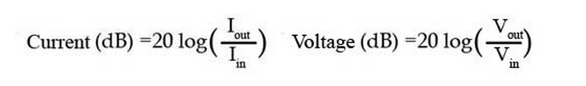
Notice that converting voltage ratios to dBs uses 20 log(Vout/Vin)
Describing the voltage gain of an amplifier that produces an output voltage of 3.5V for an input of 35mV as being 40dB,
is equivalent to saying that the output voltage is 100 times greater than the input voltage.
To reverse the process, and convert dBs to a voltage ratios for example, use:

Note that the brackets are important and antilog may be shown on calculator keypads as 10x or 10^
and is also usually Shift +log.
Use the same formula for dBs to Current gain ratio, and to convert dBs to a power ratio, simply replace the 20 in the formula with 10.

An advantage of using dBs to indicate the gain of amplifiers is that in multi stage amplifiers,
the total gain of a series of amplifiers expressed in simple ratios, would be the product of the individual gains:
Av1 x Av2 x Av3 x Av4 ...etc.
This can produce some very large numbers,
but the total of individual gains expressed in dBs would be the sum of the individual gains:
Av1 + Av2 + Av3 + Av4 ...etc.
Likewise losses due to circuits such as filters, attenuators etc. are subtracted to give the total loss.
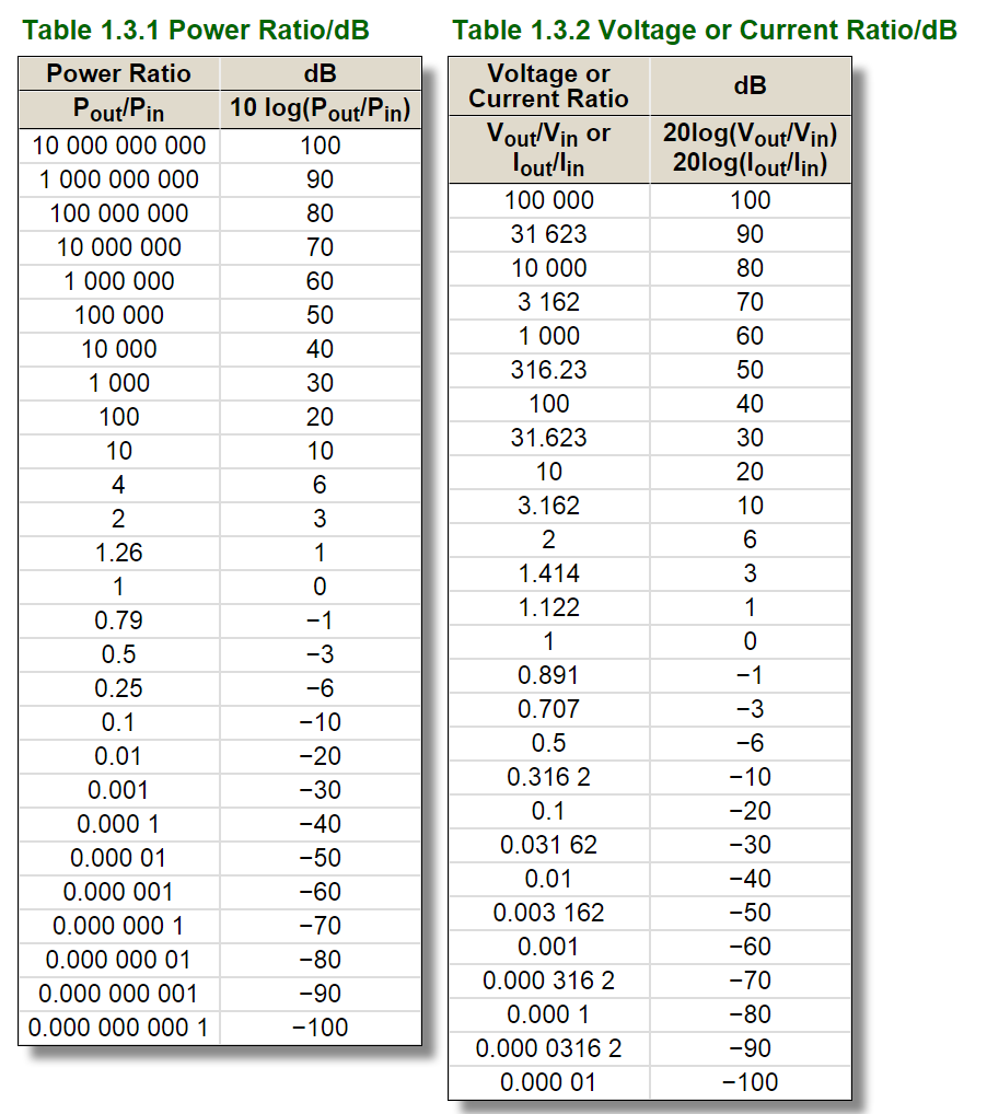
Commonly Encountered dB Values
0dB The reference level to which all +dB and −dB figures refer.
±1dB The least noticeable change in audio levels, also used for the limits of bandwidth on high quality audio amplifiers.
−3dB Commonly used for limits of bandwidth in amplifiers, indicating the points where:
a. The output voltage has fallen to 0.707 of the maximum (mid band) output.
b. The output power has fallen to half the maximum or mid band power.
(Half the VOLTAGE amplitude is −6dB)
Figures often quoted on attenuators designed to reduce the outputs on signal generators by measured amounts.
−20 dB Signal voltage amplitude divided by 10
−40dB Signal voltage amplitude divided by 100
Converting Between dBs and Power or Voltage gain