
LPCScrypt, DFUSec : USB FLASH download, programming, and security tool, LPC-Link 2 Configuration tool, Firmware Programming
What does this tool do?
The LPC18xx/43xx DFUSec utility is a Windows PC tool that provides support functions for LPC18xx/43xx microcontroller via USB. The tool is composed of 3 components: the Image Programmer, the LPC-Link 2 Configuration Tool, and the Security Support Tool (v2.00). This tool has been called the LPC18xx/43xx DFU Utility (DFUUtil) or DFUSec in versions prior to v1.10. DFUSec is the common name for the tool that covers all these components,
For instructions on how to use a specific capability of the DFUSec tool, use the menu on the right.
Where to download and download pre-requisites
Update: DFUSec and the LPC-Link 2 Configuration Tool are the same tool. Download DFUSec from the LCT link below and enable 'DFUSEC' mode by unchecking the Link2 lock button on the LCT file menu. As of v2.00 of the LCT, you no longer need to manually install .NET or the driver package - the installer will do that for you if it already isn't installed. WinUSB only needs to be installed on Windows XP machines - it is already part of Win 7/8. All you need to do is download and install the LCT.
Before you can use DFUSec, you'll need to install WINUSB and the Microsoft.NET framework 4.
DFUSec is available in pre-configured packages for the Image Programmer, Link Configuration Tool (LCT), and the (upcoming) Security Tool.
Image Programmer
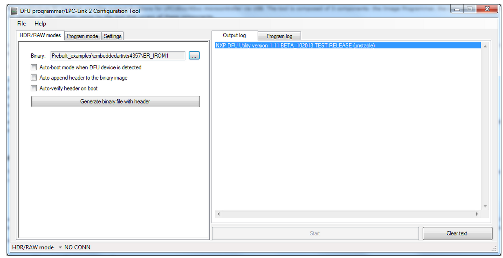
The Image Programmer uses the USB DFU boot capability of the LPC18xx/43xx devices to program the internal FLASH or EEPROM, or the SPIFLASH on some boards. To do this, a small USB image is first downloaded to the board via USB using DFU and then it communicates with the PC application. To use the Image Programmer, the a USB port must be connected for USB boot with the LPC18xx/43xx device. Most commercial boards - such as boards from Embedded Artists, Hitex, Keil, and NGX - provide this support.
The Image Programmer provides the following capabilities:
- In circuit programming and re-programming of internal FLASH and internal EEPROM on all LPC18xx/43xx devices via USB
- In circuit programming and re-programming of some SPIFLASH devices available on LPC18xx/43xx boards
- Smiple DFU download and execution of an image in IRAM with optional automated download whenever a board is plugged in
- Optional checksum generation at program time
- Boot header generation (needed by SPIFLASH or DFU boot)
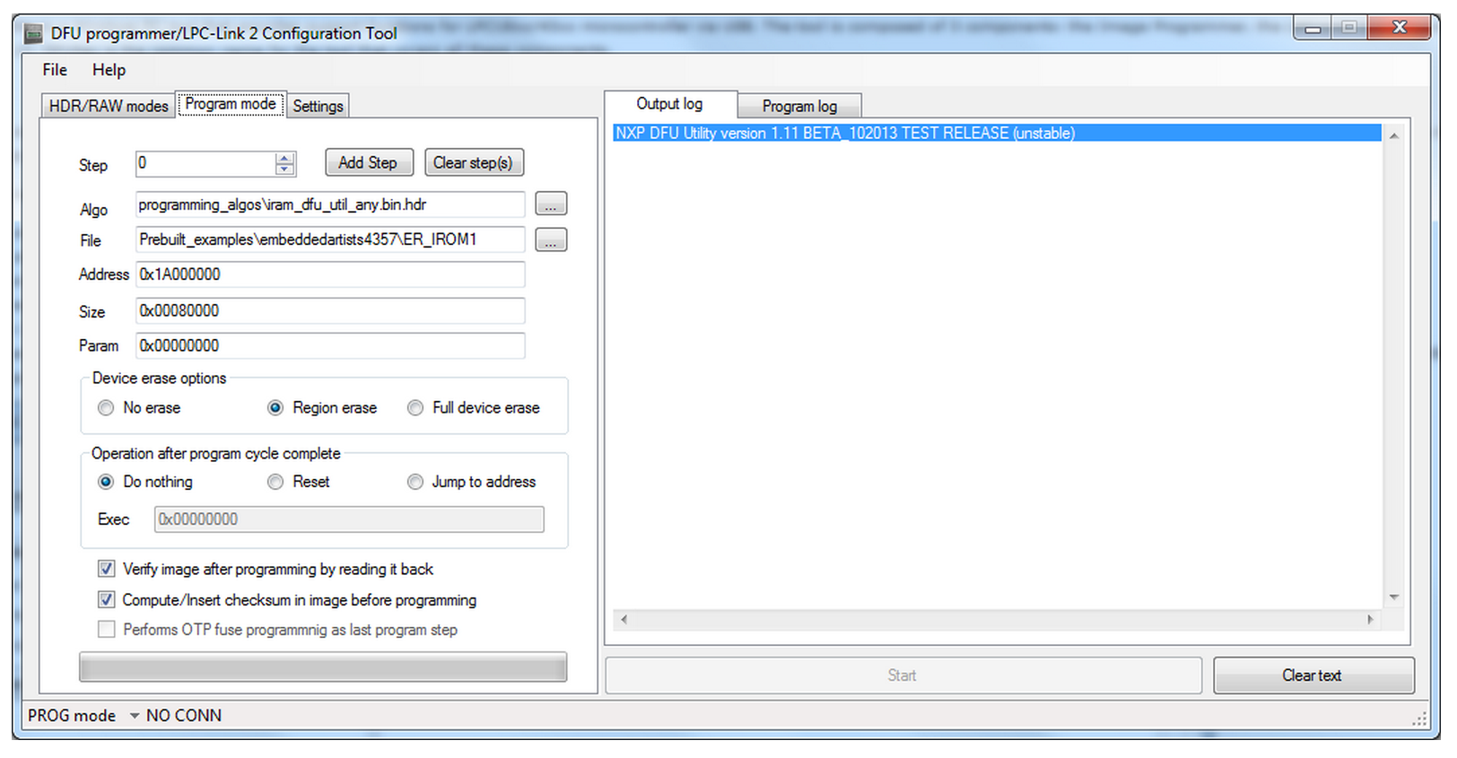
- Sequenced program operations for complex image layouts across multiple storage (internal FLASH, internal EEPROM, SPIFLASH) types - a single session can quickly program all storage with a single automated USB sessions
- Extendable FLASH support - add support for other storage devices in the programming algorithm firmware
LPC-Link 2 Configuration tool
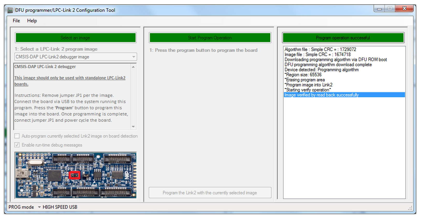
The LPC-Link 2 Configuration Tool is used to load firmware images onto the LPC-Link-2 board ir LPCXpresso V2 boards with the integrated LPC-Link 2 (LINK DFU) interface. This allows loading a firmware image that supports debugging via USB such as JLINK or CMSIS-DAP for development environments other than the LPCXpresso-IDE. To use the tool, select an image for a support LPC-Link 2 boards and follow the in-page instructions.
Security Support Tool (upcoming)
The Security Support Tool will be available with the DFUSec v2.00 release. This component of DFUSec adds the following capabilities:
- AES key management - key and vector generation, programming, and (limited) key retrieval
- Encrypted image generation with support for CMAC header
- Boot mode locking - disable JTAG, USB, or other capabilities for production systems
- Ability to encrypt FLASH binaries from Image Programmer to allow re-programming a secure board (if not locked)
LPC-Link 2 Configuration Tool
Important Notes : Read before downloading and using
- The use of the LPC-Link2 Configuration Tool is no longer recommended
- The functionality offered by this tool has been superseded by LPCScrypt.
- Download LPCScrypt to obtain the latest versions of CMSIS-DAP and J-Link firmware for LPC-Link2 or LPCXpresso V2/V3 boards.
The LPC-Link 2 Configuration Tool (LCT) is a Windows tool that installs the CMSIS-DAP/VCOM/LPCSIO or JLINK firmware on LPCXpresso V2/V3 and LPC-Link 2 boards. This package provides the Link Configuration Tool, all necessary Windows drivers, a User Manual, and the source and project files to rebuild the programming algorithm firmware used by the LCT. The V2 version provides expanded capability for LPCXpresso V2/V3 boards with improvements to CMSIS-DAP, a UART bridge connected to the target processor (LPCXpresso V2/V3 boards only), and a LPCSIO bridge that provides communication to I2C and SPI slave devices on LPCXpresso V3 boards. For LPC-Link 2 boards, an updated version of CMSIS-DAP provides faster programming and more stable operation. This version also adds support for J-Link - please see SEGGER's website for more information: for lpc-link2 boards and for LPCXpresso V2/V3 boards.
Firmware included in this package:
- LPCXpresso V2/V3 boards: CMSIS-DAP debugger + VCOM (UART bridge connected to target processor) + LPCSIO bridge (I2C + SPI + GPIO bridge connected to target processor)
- LPC-Link 2 boards: CMSIS-DAP firmware
- LPC-Link 2 and LPCXpresso V2 and V3 boards: J-Link firmware
If you are using LPC-Link 2 or LPCXpresso V2/V3 boards with the LPCXpresso-IDE, you do not need to use this tool.
Note that the LCT requires NET4.5.1 to be installed prior to use. This package will automatically download and install NET4.5.1 if it is needed. The older v1.xx versions of the LCT require NET4 to be download and installed manually prior to use.
Getting Started
Go here to get a quick guide on how to use the LCT tool to install firmware on supported boards. The LCT installer will install a User Manual that shows the LCT steps to program the firmware into your board. This User Manual can be selected from the start menu.
Known issues
- The LCT may not correctly enumerate when used with a Virtual Machine (VM). It is recommended not to use this on a VM.
- Version of the LCT >= v2.01 will not work on Windows XP systems. You can only use the v2.00 older version for Windows XP systems. Download it here.

LPCScrypt Overview
Important Note :
From v1.5 onwards, LPCScrypt is the recommenced tool for programming the latest versions of CMSIS-DAP
and J-Link firmware onto LPC-Link2 or LPCXpresso V2/V3 boards.
LPCScrypt is a command-line based, fast flash, EEPROM, OTP and security programming tool for the LPC1800 and LPC4300 series of microcontrollers.
Key features include:
- Multi-Platform Support (Windows, Mac, Linux)
- Scriptable command line interface
- Programming of internal and SPIFI flash
- Support for a wide range of SPIFI devices (via use of LPCOpen lpcspifilib)
- Optimised for high speed operation - typically 100-300KB/sec, depending upon flash device, host OS and host computer.
- Programming EEPROM (internal flash parts only)
- Programming One-Time Programmable (OTP) memory
- Images and scripts to program LPC-Link2 and LPCXpresso V2/V3 debug probe firmware
LPCScrypt consists of two parts, a multi-platform command line tool and an MCU firmware monitor.
In use, the firmware monitor is downloaded to the target MCU using USB DFU support built into the on-chip ROM (using USB0 or USB1).
The firmware creates a virtual serial port (VCOM) over USB to communicate with the host.
The LPCScrypt host tool provides a command-line interface to the firmware, giving access to the programmable features of the MCU.
It can be invoked with a single command or a script file containing a sequence of commands.
Standard host tools, such as Windows batch files or Linux/Mac shell scripts, can be used with the LPCScrypt host tool to automate multiple operations,
such as binary file encryption, programming binary files to flash devices, setting boot options, configuring VID/PID, and finally simulating MCU reset.
LPCScrypt is flexible and fast, and is suitable for one off programming and testing or semi-automated production programming.
An enhanced version of LPCScrypt with additional support for the security features of the LPC18S00 and LPC43S00 parts is available,
subject to Export Control regulations. This enhanced version adds:
- Generating and programming 128 bit AES keys
- Encrypting and programming secure images
Contact your local NXP representative to obtain the enhanced version.

LPCScrypt Downloads
| Download | Notes | |
| LPCScrypt Documentation | Please download and read the documentation before installing/using LPCScrypt | |
| Windows Installer | v1.5.2 build 588 | Supported platforms: Windows Vista or later, 32 or 64 bit |
| Mac OS X Installer | v1.5.2 build 588 | Supported platforms: Mac OS X Mountain Lion (10.8.5) or later |
| Linux Installer | v1.5.2 build 588 | Supported platforms: LPCScrypt is only tested and supported on recent distributions of Ubuntu and Fedora (32 or 64 bit). It *may* work on other distributions but we cannot provide support if it does not. |
LPCScrypt LPC-Link2 configuration
LPC-Link2 can operate as both a debug probe and an development board for the LPC4370 MCU.
For exploring the LPC4370 with LPCScrypt:
• To boot from USB0: JP1 not fitted.
• To boot from SPIFI: JP1 fitted.
Note The MCU on the LPC-Link2 has no internal flash.
LPC-Link2 Debug Probe Firmware Programming
LPCScrypt is supplied with scripts to enable the programming of CMSIS-DAP and J-Link firmware images
into LPC-Link2 and LPCXpresso V2/V3 boards.
To make use of this functionality, configure the selected board to DFU Boot, then connect to the host computer via USB.
To install CMSIS-DAP debug firmware, open a command shell and call the program_CMSIS script:
\scripts\program_CMSIS
To install J-Link debug firmware, open a command shell and call the program_JLINK script:
\scripts\program_JLINK
For Windows uses, shortcuts to these scripts are available from the LPCScrypt entry on the Start menu.

Note
File paths in this document use Windows directory separators, on Linux or Mac OSX these must be replaced with ‘/’
These scripts will boot the LPCScrypt firmware on the selected board and
then choose the appropriate firmware image and program it into flash.
Once completed, follow the onscreen instructions to make use of the programmed debug probe.
For more information, please read the following sections for a detailed explanation of this procedure.
Note
The scripts offer the option to repeat the programming sequence to enable multiple debug probes to be programmed in sequence.
Debug Firmware Variants and Drivers
4.1 Firmware Variants
Separate firmware images are available for each LPC-Link2 variant for the following debug probe protocol implementations:
4.1.1 CMSIS-DAP
The CMSIS-DAP debug probe images allow debugging from any compatible toolchain,
including IAR EWARM, Keil MDK, as well as NXP’s LPCXpresso IDE.
As well as providing debug probe functionality, the default CMSIS-DAP image also provides:
• Support for SWO Trace capture from the LPCXpresso IDE
• Support for Power Measurement from the LPCXpresso IDE
• UART bridge connected to the target processor (LPCXpresso V2/V3 boards only),
• LPCSIO bridge that provides communication to I2C and SPI slave devices (LPCXpresso V3 boards only).
For more information please see:
http://www.lpcware.com/content/project/lpc-usb-serial-io-library
Note
If these additional features are not required, a version supporting debug features only is also provided.
For information on script options, see Section 7.2.
Note
LPCXpresso IDE does not require a CMSIS-DAP image to be programmed into the debug probe flash,
as it will normally be downloaded directly into the probe after power up.
However it can use a pre-programmed version if one is present.
4.1.2 Segger J-Link
J-Link is a trademark of Segger Embedded Software Solutions. More information about JLink can be found at: http://www.segger.com
Important Note
Please ensure that you read Segger’s licensing terms for these debug probe firmware images before using them.
For information on the use of J-Link with LPC-Link2 and LPCXpresso V2/V3, please see:
https://www.segger.com/lpc-link-2.html
https://www.segger.com/jlink-lpcxpresso-ob.html
The J-Link debug probe images allow the LPC-Link2/LPCXpressoV2/V3 board to operate as a J-Link debug probe
that works with tool chains that support the J-Link protocol such as IAR EWARM, Keil MDK, Rowley CrossWorks,
Atollic TrueSTUDIO, OpenOCD compatible tools as well as GDB-based tool chains such as emIDE.
J-Link can also be used with LPCXpresso IDE.
For details see:
https://www.segger.com/nxp-lpcxpresso.html
4.2 Drivers
You may need to install additional Windows drivers in order to make use of your debug probe.
For CMSIS-DAP, the Windows driver package if not already installed – for example by LPCXpresso IDE – can be found at:
http://www.lpcware.com/content/nxpfile/lpcxpresso-link2-usb-driverpackage
For J-Link, please check the Segger website for more information.
Programming (LPC-Link2)
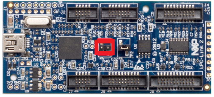
To program a standalone LPC-Link2, first of all ensure that jumper JP1 is NOT fitted so that the probe will be DFU bootable at power on.

Figure 5.1. LPCLink2 DFU Boot
Then connect the board to your host computer over the debug link USB connector and in a command shell run either:
<LPCScrypt Install Dir>\scripts\program_CMSIS
or
<LPCScrypt Install Dir>\scripts\program_JLINK
Note:
The script will automatically detect the debug probe type and select the appropriate firmware version.
Once programming is complete, disconnect the board from the host, fit JP1, then reconnect the board to the host computer.
You should see the debug probe enumerate on the host’s USB system.
Advanced
LPC-Link2 is a dual purpose debug probe and test board.
The board contains a single LPC4370 MCU and 1MB of SPIFI flash memory.
Where as, LPCXpresso V2/V3 boards, contain a dedicated 43xx debug MCU (connected via the lower left USB port)
with internal Flash memory in addition to the target MCU.
Since the debug firmware is stored in the flash memory of the debug MCU, different images are required for these board.
7.1 Script steps
This section describes the operations carried out by the program_CMSIS and program_JLINK scripts.
The scripts perform the following steps:
1. Boots the debug probe with the LPCScrypt firmware.
• this is performed by calling the script \scripts \bootLPCScrypt
• if this operation succeeds, then the script will continue, otherwise, the script will terminate with an error
2. Tests for successful communication between the host and LPCScrypt
• \bin\LPCScrypt print 0x1234 is repeatedly called until sucessful communication is achieved.
• a ‘.’ is printed for each attempt 3. Identify the debug probe MCU.
• \bin\LPCScrypt querypart is called to return the part name
• based on the result, the flash type SPIFI or BANKA is selected
4. The appropriate image file is located in the LPCScrypt firmware directory based on the identified debug probe MCU.
• if this cannot be found an error will be generated and the script will terminate
5. LPCScrypt is called to program the image onto the chosen board.
• \bin\LPCScrypt program
• if the program operation should fail, an error will be generated and the script will terminate
6. If no error has been generated, the steps will be repeated for the next device to be connected.
Note:
• for LPC-Link2, the firmware is stored in the SPIFI flash memory at 0x14000000,
so the board must be configured to boot from SPIFI memory for the CMSIS-DAP
or J-Link firmware to be used after programming (by connecting the jumper JP1)
• for LPCXpresso V2/V3 boards, the firmware is stored in flash BankA at 0x1A000000,
so the board must be re-configured to boot from BankA for the CMSIS-DAP or J-Link firmware
to be used after programming (by removing DFU Link jumper)

