STM32 Timer : Base Timer, Input Capture, PWM, Output Compare
http://www.cs.indiana.edu/~geobrown/book.pdf

An example of a basic timer is illustrated in Figure 10.1.
This timer has four components – a controller, a prescaler (PSC), an “auto-reload” register (ARR) and a counter (CNT).
The function of the prescaler is to divide a reference clock to lower frequency.
The STM32 timers have 16-bit prescaler registers and can divide the reference clock by any value 1..65535.
For example, the 24Mhz system clock of the STM32 VL Discovery
could be used to generate a 1 Mhz count frequency with a prescaler of 23 (0..23 == 24 values). T
he counter register can be configured to count up, down, or up/down and to be reloaded from the auto reload register
whenever it wraps around (an “update event”) or to stop when it wraps around.
The basic timer generates an output event (TGRO) which can be configured
to occur on an update event or when the counter is enabled (for example on a GPIO input).
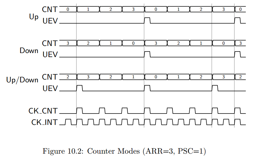
To understand the three counter modes consider Figure 10.2.
In these examples, we assume a prescaler of 1 (counter clock is half the internal clock), and a auto reload value of 3.
Notice that in “Up” mode, the counter increments from 0 to 3 (ARR) and then is reset to 0.
When the reset occurs, an “update event” is generated.
This update event may be tied to TRGO, or in more complex timers with capture/compare channels
it may have additional effects (described below).
Similarly, in “Down” mode, the counter decrements from 3 to 0 and then is reset to 3 (ARR).
In Down mode, an update “event” (UEV) is generated when the counter is reset to ARR.
Finally, in Up/Down mode, the counter increments to ARR, then decrements to 0, and repeats.
A UEV is generated before each reversal with the effect that the period in Up/Down mode
is one shorter than in either Up or Down mode.
Many timers extend this basic module with the addition of counter channels such as the one illustrated in Figure 10.3.
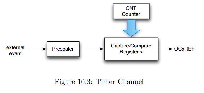
The “x” refers to the channel number – frequently, timers support multiple channels.
With this modest additional hardware, an output can be generated whenever the count register reaches a specific value
or the counter register can be captured when a specific input event occurs (possibly a prescaled input clock).
An important use of counter channels is the generation of precisely timed pulses.
There are two variations of this use – “one-pulse” pulses,
in which a single pulse is generated, and pulse width modulation, in which a series of pulses is generated with the counter UEV period.
The pulse width is controlled by the Capture/Compare Register (CCR).
For example, the channel output (OCxREF) may tied to whether the CNT register is greater (or less) than the Compare register.
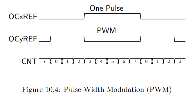
In Figure 10.4 we illustrate the use of two channels for one-pulse and PWM outputs.
Here we assume that the ARR is 7 and the CCR is 3.
In PWM mode, ARR controls the period, and CCR controls the pulse width (and hence the duty cycle).
In one-pulse mode, the pulse begins CCR cycles after an initial trigger event, and has a width of ARR-CRR.
It is possible to use multiple channels to create a set of synchronized, pulses beginning at precise delays from each other.
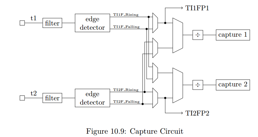
A timer channel may also be used to measure pulse widths – in effect decoding pwm signals.
There are many other configuration options for the STM32 timers including mechanisms
to synchronize multiple timers both to each other and to external signals.
In the remainder of this chapter we consider two timer applications including PWM output (Section 10.1),
input pulse measurement (Section 10.2).
In Chapter 13 we show how to use a timer to control DMA transfers for an audio player and
in Chapter 14 we use a timer to sample and analog input at regular intervals.