STM32F4 Timer Internal Trigger Connection

The Timers can be cascaded to make more complex timing relationships, or longer periods.
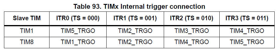
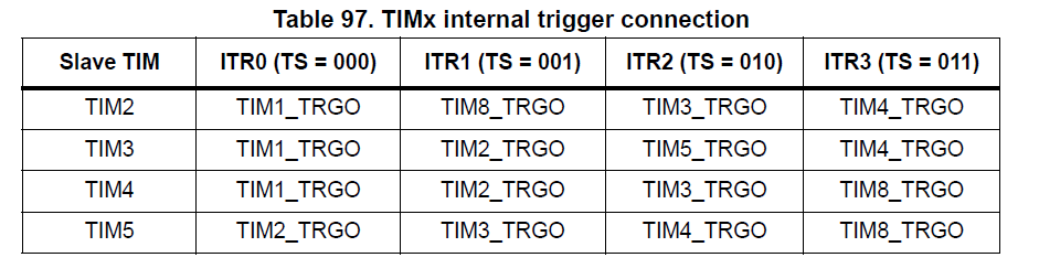
Internally only some timers can trigger others.
This is a Master/Slave relationship and is handled by the SMS register.
For example, you can see below that TIM8 can be triggerd by TIM1.

- Uses TRGI to map.
- One Timer can be used as the prescaler for another.
- The first timer update_event, or output_compare signal is used as clock for the second.
- The counter mode sets whether the update_event occurs on overflow and/or underflow of the Timer
- Counter mode is set using the TIMx_CR1 reg and CMS bits as indicated in the example below.
Example for internal trigger
Internal trigger clock mode 1 (ITRx)
TIM_CLK is replaced by ITRx_CLK which is the internal trigger freq mapped to timer Trigger input TRGI.
The counter mode indicates if the update_event is generated:
- on overflow - if mode = up counting, the DIR bit is reset in TIMx_CR1
- on underlfow - if mode = down counting, the DIR bit is set in TIMx_CR1
- both - if mode is center aligned, the CMS bits are non zero
The update_event is also generated by:
- software if the UG bit (Update Generation) is set in TIM_EGR reg.
- update generation through the slave mode controller
refer to Timer app note: DM00042534.pdf
Timer synchronisation
A Master can control a slave Timer using a Trigger TRGO.
A Timer is slaved if its ITRx is connected to a Slave and the Master is set to use TRGO
Trigger outputs from the Master can be selected from:
- Reset:
- UG bit from EGR reg is used as TRGO
- UG bit from EGR reg is used as TRGO
- Enable:
- Counter enable is used as TRGO.
- Used to start several timers at the same time or control window for Slave start
- Update:
- the update_event is TRGO.
- e.g. a master timer can act as a prescaler for a slave timer.
- Compare pulse:
- as soon as a capure or match occurs TRGO goes high when CC1IF flag is to be set
- as soon as a capure or match occurs TRGO goes high when CC1IF flag is to be set
- OC1REF: use OC1REF as TRGO
- OC2REF: use OC2REF as TRGO
- OC3REF: use OC3REF as TRGO
- OC4REF: use OC4REF as TRGO
Master mode:
- Configure the Timer
- Select Trigger output to be used
- in CR2 reg - set MSM bits
- Enable Master/slave mode
- in SMCR reg - enable MSM bit
/*
 * Trigger select mapping for slave timer from master timer.  This is
 * unfortunately not very straightforward; there's no tidy way to do this
 * algorithmically.  To avoid burning memory for a lookup table, use macros to
 * compute the offset.  This also has the benefit that compilation will fail if
 * an unsupported master/slave pairing is used.
 *
 * Slave        Master
 *     1    15  2  3  4  (STM32F100 only)
 *     2     9 10  3  4
 *     3     9  2 11  4
 *     4    10  2  3  9
 *     9     2  3 10 11  (STM32L15x only)
 *     --------------------
 *     ts =  0  1  2  3
 */
#define STM32_TIM_TS_SLAVE_1_MASTER_15 0
#define STM32_TIM_TS_SLAVE_1_MASTER_2  1
#define STM32_TIM_TS_SLAVE_1_MASTER_3  2
#define STM32_TIM_TS_SLAVE_1_MASTER_4  3
#define STM32_TIM_TS_SLAVE_2_MASTER_9  0
#define STM32_TIM_TS_SLAVE_2_MASTER_10 1
#define STM32_TIM_TS_SLAVE_2_MASTER_3  2
#define STM32_TIM_TS_SLAVE_2_MASTER_4  3
#define STM32_TIM_TS_SLAVE_3_MASTER_9  0
#define STM32_TIM_TS_SLAVE_3_MASTER_2  1
#define STM32_TIM_TS_SLAVE_3_MASTER_11 2
#define STM32_TIM_TS_SLAVE_3_MASTER_4  3
#define STM32_TIM_TS_SLAVE_4_MASTER_10 0
#define STM32_TIM_TS_SLAVE_4_MASTER_2  1
#define STM32_TIM_TS_SLAVE_4_MASTER_3  2
#define STM32_TIM_TS_SLAVE_4_MASTER_9  3
#define STM32_TIM_TS_SLAVE_9_MASTER_2  0
#define STM32_TIM_TS_SLAVE_9_MASTER_3  1
#define STM32_TIM_TS_SLAVE_9_MASTER_10 2
#define STM32_TIM_TS_SLAVE_9_MASTER_11 3