
STM32F4 External event -- WFE 待机模式
The STM32F4xx are able to handle external or internal events in order to wake up the core (WFE).
The wakeup event can be generated either by:
-
(I've removed normal external interrupt mode details)
-
or configuring an external or internal EXTI line in event mode.
When the CPU resumes from WFE,
it is not necessary to clear the peripheral interrupt pending bit
or the NVIC IRQ channel pending bit as the pending bit corresponding to the event line is not set.
唤醒事件管理
STM32 可以处理外部或内部事件来唤醒内核(WFE)。唤醒事件可以通过下述配置产生:
在外设的控制寄存器使能一个中断,但不在NVIC中使能,同时在Cortex-M3的系统控制寄存器中使能SEVONPEND位。
当CPU从WFE恢复后,需要清除相应外设的中断挂起位和外设NVIC中断通道挂起位(在NVIC中断清除挂起寄存器中)。
配置一个外部或内部EXTI线为事件模式,当CPU从WFE恢复后,因为对应事件线的挂起位没有被置位,
不必清除相应外设的中断挂起位或NVIC中断通道挂起位。
SEVONPEND位,这个位是什么作用呢?权威指南这么说:
发生异常悬起时请发送事件,用于在一个新的中断悬起时从 WFE 指令处唤醒。
不管这个中断的优先级是否比当前的高,都唤醒。
如果没有 WFE导致睡眠,则下次使用 WFE 时将立即唤醒
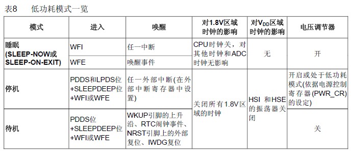
在以下条件下执行WFI(等待中断)或WFE(等待事件)指令:
– 设置Cortex-M3系统控制寄存器中的SLEEPDEEP位
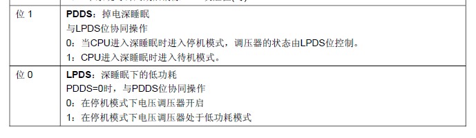
– 清除电源控制寄存器(PWR_CR)中的PDDS位 进入
– 通过设置PWR_CR中LPDS位选择电压调节器的模式
注:为了进入停止模式,所有的外部中断的请求位(挂起寄存器(EXTI_PR))
和RTC的闹钟标志都必须被清除,否则停止模式的进入流程将会被跳过,程序继续运行
如果执行WFI进入停止模式: 设置任一外部中断线为中断模式(在NVIC中必须使能相应的外部中断向量)。
如果执行WFE进入停止模式: 设置任一外部中断线为事件模式。
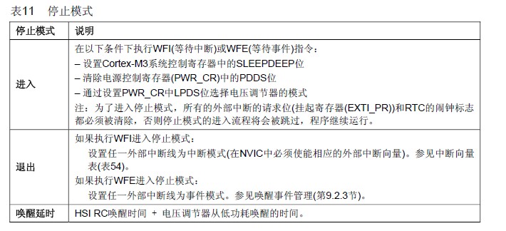
//进入停止模式
{
  u32 tmpreg tmpreg = PWR->CR;
  tmpreg &= ~(1<<1);      //清除PWR_CR的PDDS
  tmpreg |=(1<<0);      //设置PWR_CR的 LPDS
  PWR->CR = tmpreg;
  SCB->SCR|=1<<2;       //使能SLEEPDEEP位 (SYS->CTRL)
  __WFI();              //执行WFI指令
}
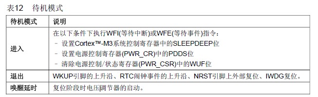

//进入待机模式
void Sys_Standby(void)
{
  SCB->SCR|=1<<2;         // 使能SLEEPDEEP位 (SYS->CTRL)
  RCC->APB1ENR|=1<<28;    // 使能电源时钟
  PWR->CSR|=1<<8;         // 设置WKUP用于唤醒
  PWR->CR|=1<<2;          // 清除Wake-up 标志(WUF位)
  PWR->CR|=1<<1;          // PDDS置位
  __WFI();                // 执行WFI指令
}
So it appears the main purpose is to enable wakeups without generating an interrupt
or having to respond to interrupts during normal operation.
It's not mentioned in that guide and I'm not sure how applicable is to the STM32 architecture
but on some other devices similar schemes can be useful to catch fast events without generating an interrupt.
For example you may have an application where it's important to capture that a sub-microsecond event has occurred,
but there's no need to respond to it quickly so you can just check a flag to see if it's occurred.
4.3.3 of the reference manual says:
If the WFE instruction is used to enter Sleep mode, the MCU exits Sleep mode as soon as an event occurs.
This event can be either an interrupt enabled in the peripheral control register but not in the NVIC,
or an EXTI line configured in event mode.
Has anybody managed to set WFE and exit it using "an interrupt enabled in the peripheral control register but not in the NVIC" ?
This implies any interrupt flag will do it, but it only wakes up for me if the interrupt is set in the nvic (and executes).
I haven't tried it myself, but it looks like there are two way to do it.
The ST reference manual seems to be referring the method 1 below:
1) Using the Event mask register.
Beside from enabling the interrupt in the peripheral control, you also need to set the Event Mask Register (EXTI_EMR)
(section 8.3.2) to enable the peripheral to trigger the event signal.
And base on the circuit diagram in figure 16 (section 8.2.2) you also need to make sure
you set the interrupt source as rising edge trigger or falling edge trigger.
(so in total you must set up as least two registers on top of the peripheral's interrupt enable).
2) Use SEVONPEND feature on NVIC
This control bit is in bit[4] of NVIC System Control Register (0xE000ED10) is SEVONPEND control for NVIC.
When a new interrupt pending occurred, this should be able to
generate a internal event in the NVIC to wake up the core
To use the event mask resister, I think the event needs to be one of those linked to an exti line.
However, setting the SEVONPEND bit works perfectly :)
If anyone's looking, theres a firmware library function to do it:
NVIC_SystemLPConfig(NVIC_LP_SEVONPEND, ENABLE);
I have noticed that my __WFE(); sometimes returns immdiately.
This is described in D.7.68 of the ARMv7M Architecture Application Level Reference Manual:
If the Event Register is set, Wait For Event clears it and returns immediately.
By calling WFE twice in succession:
If the Event Register is Set, the first WFE will clear it, and the second will sleep.
If the Event Register is not set, the first will sleep until it is set, and then the second will clear it.
However, this is clearly unsafe, since if the actual event occurs before the first WFE
(e.g. delayed by an interrupt) then it will sleep until a further event occurs (if one ever does).
Does anybody know the address of the Event Register to clear it properly?
The arm "Application Level" manual suggests calling ClearEventRegister(),
and the proper manual is not available for download.
Use the following assembly sequence:
SEV ; Send Event , this set the event register to 1
WFE ; 1st WFE will not cause sleep, but will cause event reg to clear
WFE ; 2nd WFE will cause sleep
Excellent, thanks again Joseph!
Just another note to anyone else trying this;
before calling WFE make sure that you clear the pending bit in the nvic
that you are waiting to see change (e.g. call NVIC_ClearIRQChannelPendingBit).
I forgot to mention a corner case:
If you use SEV - WFE - WFE sequence, and if there is a interrupt take place
between the two WFE, the event register will get set again
and the second WFE will not enter sleep.
Alternatively, you could use a loop to handle this
  int loopexit = 0;
  while ( loopexit == 0 )
  {
    __WFE( ); // Try to sleep
    if ( Check_If_Work_Need_To_Be_Done( ) )
    {
      Do_Some_Work( );
    }
    loopexit = Check_If_Want_To_Exit_Sleep( );
  }
In this way it doesn't matter what is the current value of the event register,
as it will repeat the __WFE until it entered sleep or if you want it to exit from sleep.
Here is an example of using WFE with EXTI. Hope that helps you.
int main( void )
{

  /*!< At this stage the microcontroller clock setting is already configured,
   this is done through SystemInit() function which is called from startup
   file (startup_stm32f37x.s) before to branch to application main.
   To reconfigure the default setting of SystemInit() function, refer to
   system_stm32f37x.c file
   */

  /* Configure PA0 in interrupt mode */
  EXTI0_Config( );

  /* Configure LEDs */
  STM_EVAL_LEDInit( LED1 );
  STM_EVAL_LEDInit( LED2 );
  STM_EVAL_LEDInit( LED4 );

  /* SysTick interrupt each 10 ms */
  if ( SysTick_Config( SystemCoreClock / 100 ) )
  {
    /* Capture error */
    while ( 1 );
  }

  /* LED1 On */
  STM_EVAL_LEDOn( LED1 );

  /* Request to enter STOP mode with regulator in low power mode */
  PWR_EnterSTOPMode( PWR_Regulator_LowPower, PWR_STOPEntry_WFE );

  /* LED1 On */
  STM_EVAL_LEDOn( LED2 );

  while ( 1 )
  {
  }
}

/**
 * @brief  Configure PA0 in interrupt mode
 * @param  None
 * @retval None
 */

static void EXTI0_Config( void )
{
  EXTI_InitTypeDef EXTI_InitStructure;
  GPIO_InitTypeDef GPIO_InitStructure;

  /* Enable GPIOA clock */
  RCC_AHBPeriphClockCmd( RCC_AHBPeriph_GPIOA, ENABLE );

  /* Configure PA0 pin as input floating */
  GPIO_InitStructure.GPIO_Mode = GPIO_Mode_IN;
  GPIO_InitStructure.GPIO_PuPd = GPIO_PuPd_NOPULL;
  GPIO_InitStructure.GPIO_Pin = GPIO_Pin_0;
  GPIO_Init( GPIOA, &GPIO_InitStructure );
  /* Enable SYSCFG clock */
  RCC_APB2PeriphClockCmd( RCC_APB2Periph_SYSCFG, ENABLE );

  /* Connect EXTI0 Line to PA0 pin */
  SYSCFG_EXTILineConfig( EXTI_PortSourceGPIOA, EXTI_PinSource0 );

  /* Configure EXTI0 line */
  EXTI_InitStructure.EXTI_Line = EXTI_Line0;
  EXTI_InitStructure.EXTI_Mode = EXTI_Mode_Event;
  EXTI_InitStructure.EXTI_Trigger = EXTI_Trigger_Rising;
  EXTI_InitStructure.EXTI_LineCmd = ENABLE;
  EXTI_Init( &EXTI_InitStructure );
}
  /* init the TIM7 */
  RCC->APB1ENR |= RCC_APB1ENR_TIM7EN;
  TIM7->PSC = 7; // => 1 MHz timer clock frequency (at PCLK=8 MHz)
  TIM7->ARR = 1000 - 1; // => 1 kHz interrupt rate
  TIM7->DIER = TIM_DIER_UIE; // enable the update interrupt
  NVIC_EnableIRQ( TIM7_IRQn );
  TIM7->CR1 |= TIM_CR1_CEN; // start the timer

  RCC->APB1ENR |= RCC_APB1Periph_PWR;

  /* Configure PA0 pin as input floating */
  RCC->AHBENR |= RCC_AHBPeriph_GPIOA;
  RCC->APB2ENR |= RCC_APB2Periph_SYSCFG;

  GPIO_InitStructure.GPIO_Pin = GPIO_Pin_0;
  GPIO_InitStructure.GPIO_Mode = GPIO_Mode_IN;
  GPIO_Init( GPIOA, &GPIO_InitStructure );

  EXTI_InitStructure.EXTI_Line = EXTI_Line0;
  EXTI_InitStructure.EXTI_Mode = EXTI_Mode_Event;
  EXTI_InitStructure.EXTI_Trigger = EXTI_Trigger_Rising;
  EXTI_InitStructure.EXTI_LineCmd = ENABLE;
  EXTI_Init( &EXTI_InitStructure );

  SYSCFG_EXTILineConfig( EXTI_PortSourceGPIOA, EXTI_PinSource0 );

  PWR_WakeUpPinCmd( PWR_WakeUpPin_1, ENABLE );

  /* Configure the pin to be toggled: PB2 */
  RCC->AHBENR |= RCC_AHBPeriph_GPIOB;
  GPIO_InitStructure.GPIO_Pin = GPIO_Pin_1;
  GPIO_InitStructure.GPIO_Mode = GPIO_Mode_OUT;
  GPIO_InitStructure.GPIO_OType = GPIO_OType_PP;
  GPIO_Init( GPIOB, &GPIO_InitStructure );

  /* Configure PWR registers to enter STOP mode */
  PWR->CR &= 0xFFFFFFFC;   // clear the PDDS and LPDS bits
  PWR->CR |= 0x00000000;   // STOP Mode: Regulator on
  //PWR->CR |= 0x00000001; // STOP Mode: Regulator off

  /* Set SLEEPDEEP bit of Cortex System Control Register */
  SCB->SCR |= SCB_SCR_SLEEPDEEP_Msk;
  __WFE( );

  /* after waking-up from STOP mode this is the first instruction to be executed */
  SCB->SCR &= (uint32_t) ~( (uint32_t) SCB_SCR_SLEEPDEEP_Msk );

  /* Configure PB1 as Output */
  GPIOB->ODR = 0x00000002;
Seeing the following explanation for WFE command from ARM,
I suspect that the event register is 1. But I don't have an explanation why.
This is the ARM explanation:
WFE is a hint instruction.
If the event register is 0, WFE suspends execution until one of the following events occurs:
- an exception, unless masked by the exception mask registers or the current priority level
- an exception enters the Pending state, if SEVONPEND in the System Control Register is set
- a Debug Entry request, if Debug is enabled
- an event signaled by a peripheral or another processor in a multiprocessor system using the SEV instruction.
If the event register is 1, WFE clears it to 0 and returns immediately.
That is why the second WFE works fine.
We have 2 instructions for entering low-power standby state
where most clocks are gated: WFI and WFE.

WFE: Wait For Event
WFI: Wait For Interrupt

They differ slightly in their entry and wake-up conditions,
with the main difference being that WFE makes use of the event register,
the SEV instruction and EVENTI, EVENTO signals.

WFI is targeted at entering either standby, dormant or shutdown mode,
where an interrupt is required to wake-up the processor.

A usage for WFE is to put it into a spinlock loop.
Where a CPU wants to access a shared resource such as shared memory,
we can use a semaphore flag location managed by exclusive load and store access.
If multiple CPUs are trying to access the resource,
one will get access and will start to use the resource
while the other CPUs will be stuck in the spinlock loop.

To save power, you can insert the WFE instruction into the loop
so the CPUs instead of looping continuously will enter STANDBTWFE.
Then the CPU who has been using the resource should execute SEV instruction
after it has finished using the resource.
This will wake up all other CPUs from STANDBYWFE
and another CPU can then access the shared resource.

The reason for having EVENTI and EVENTO is to export a pulse on EVENTO
when an SEV instruction is executed by any of the CPUs.
This signal would connect to EVENTI of a second Cortex-A5 MPCore cluster
and would cause any CPUs in STANDBYWFE state to leave standby.

So these signals just expand the usage of WFE mode across multiple clusters.
If you have a single cluster, then you do not need to use them.

