AT91 USB Composite Driver Implementation
AT91 USB Composite Driver Implementation
1. Introduction The USB Composite Device is a general way to integrate two or more functions into one single device.
It is defined in the USB Specification Revision 2.0, as "A device that has multiple interfaces controlled independently of each other".
This document introduces basics for USB composite device and gives examples to implement the composite device
that has two functions included, based on the Atmel® AT91 SAM Softpack for its ARM® Thumb® based microcontrollers.
To add more than one functions to the host via one USB port, the USB composite device works.
The available functions are listed as following:
• MSD: To extend hard disk storage capacity.
• HID: USB mouse, USB keyboard, Game controller ...
• Audio: USB Speaker or Recorder for host.
• CDC: To work as virtual COM port, modems or networking devices such as ADSL or Cable modem.
For more detailed information, please refer to the Application Notes of the class related device implementations.
Normally when you use USB functions, you will need one USB cable for each function, which means when you use several functions, many cables are needed.
The composite device helps to reduce the number of cables used at the same time.
This Application Note details the following composite solutions:
• HID + MSD: Adds keys, navigation pads or even handwrite pad with a storage disk.
• HID + Audio: Integrates game controller with Audio codec.
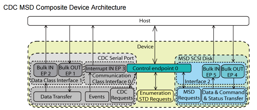
• CDC + MSD: Add more serial ports or modems when extending the storage of your laptop.
• CDC + Audio: Modem and an audio speaker at the same time. Or extend your serial port when you are playing music.
• CDC + HID: Extends the interface mostly for laptops, which allows extra serial port and mouse/keyboard.
• CDC + CDC: To extends two or more serial ports through one single USB cable, mostly for laptop.
Note that the composite device has several functions that work concurrently.
The host can see all of these functions available simultaneously.
Some of the cellphones that can manually select their connection types as “Modem” or “USB Disk”
is just product with two different USB devices pre-selected and not “composite” one.
3. USB Composite Device Basics
3.1 Purpose The Universal Serial Bus (USB) offers an easy way to connect PC with portable devices and to expand external peripherals.
Usually a USB device provides a single function to the host,
such as a storage disk, serial RS-232 port, digital microphone, or speakers, so one function occupies one USB port.
Nevertheless, to allow several functions through a single physical port, the USB specification mentions two kinds of devices:
• Composite device: a device has multiple logical interfaces controlled independently of each other.
A single physical logical address is used for the device.
• Compound device: a separate hub with multiple functions attached.
Composite devices are an efficient solution to reduce the number of hub and USB cables.
To give an example:
a device being at the same time modem and audio speaker requires only a single USB cable.
3.2 Architecture
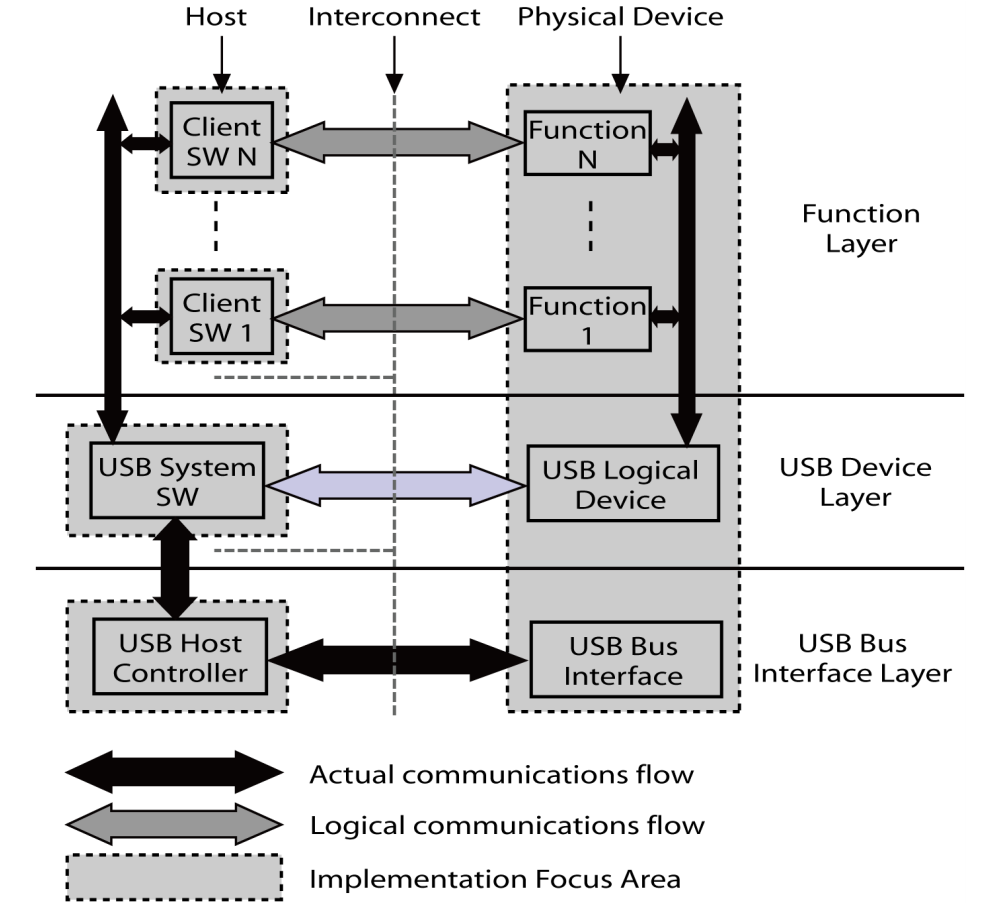
3.2.1 Communication flow
Figure 3-3 highlights logical communication flows between several clients (host side) and functions (device side),
over a single physical USB connection.
The highlighted layer is the function layer. In host side, there is some client software that can operate with the different functions in the same physical device simultaneously. E.g. when a composite device with card reader and printing function is connected to a PC, a new printer device and storage disks may appear for you to explore your pictures on your media card, and to print them with the printer.
3.2.2 Interfaces Interface descriptors for composite devices correspond to the concatenation of interfaces descriptors defined for each functions available in the system.
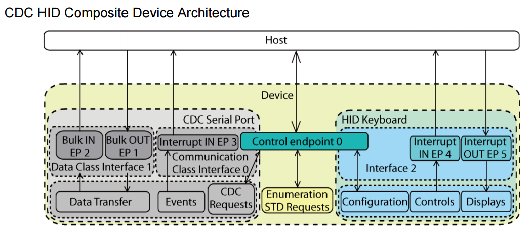
E.g., a composite with HID+CDC needs three interface descriptors (Section 4.7.3 on page 15), while HID+MSD (Section 4.7.1 on page 13) only needs two.
There are some general rules to assemble the interfaces:
• bInterfaceNumber should start from zero and then increase by one;
• the interfaces that use the same function should be placed together, that is, the values of bInterfaceNumber should be contiguous;
• if two or more interfaces are associated to one device function (such as CDC), the Interface Association Descriptor (IAD) is used,
please refer to Section 3.2.4.1 on page 6 for more details.
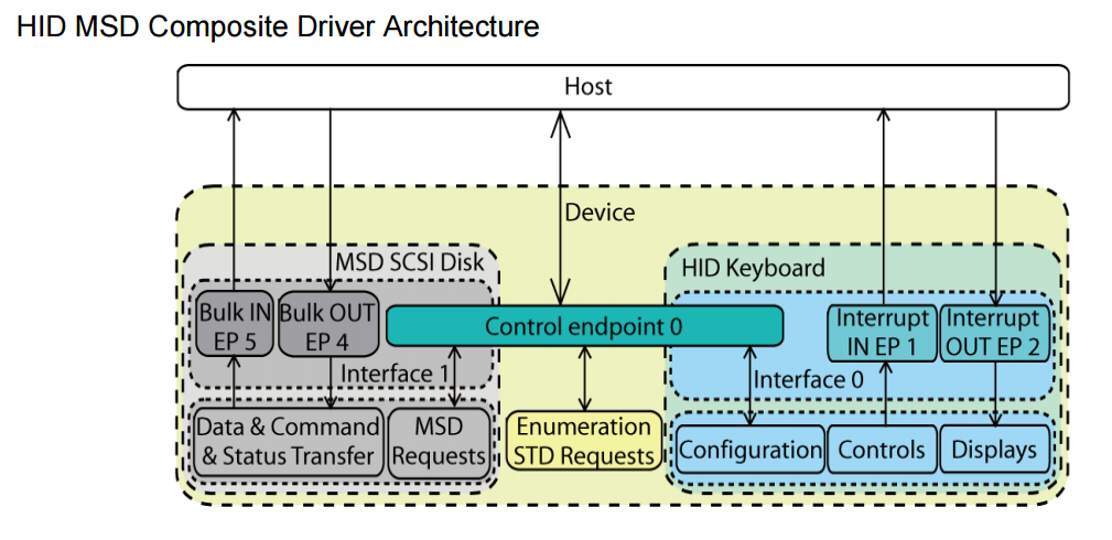
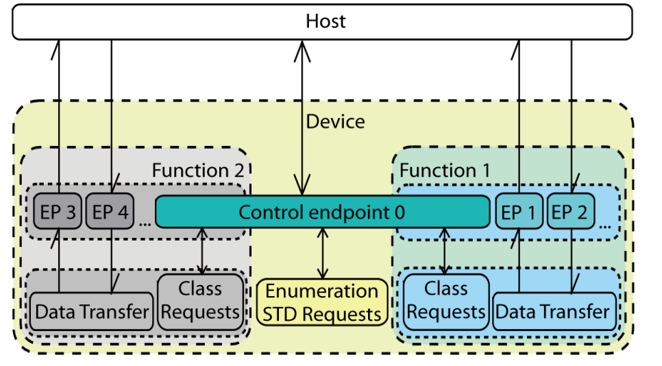
3.2.2.1 Composite with SINGLE-interface functions
This kind of composite device includes the functions that have only one interface, such as HID+MSD.
The default endpoint (endpoint 0) is shared by all functions.
Each function has one interface only, to handle class-specific requests, control commands and data.
The interface and endpoint settings are function specific.
Figure 3-1. USB Composite Device with SINGLE-interface-functions
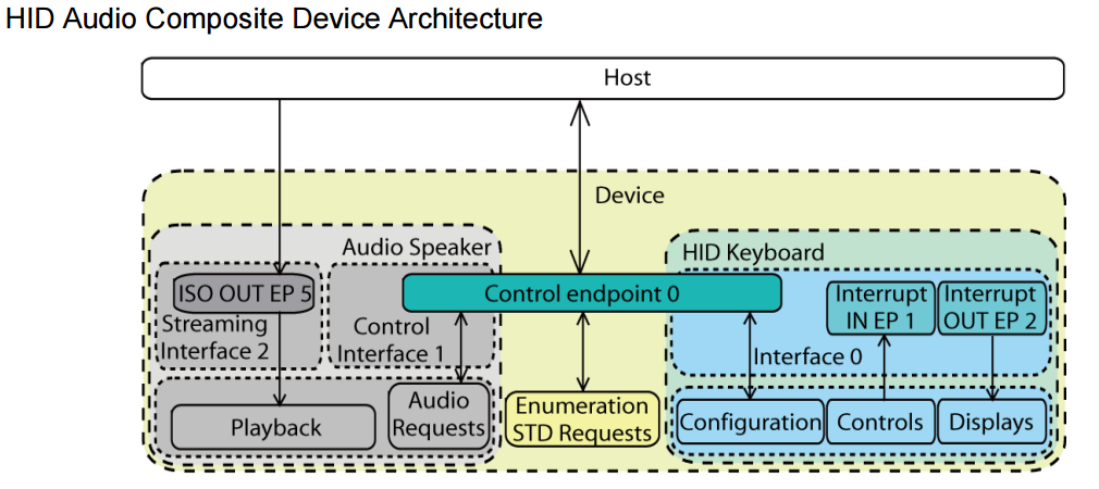
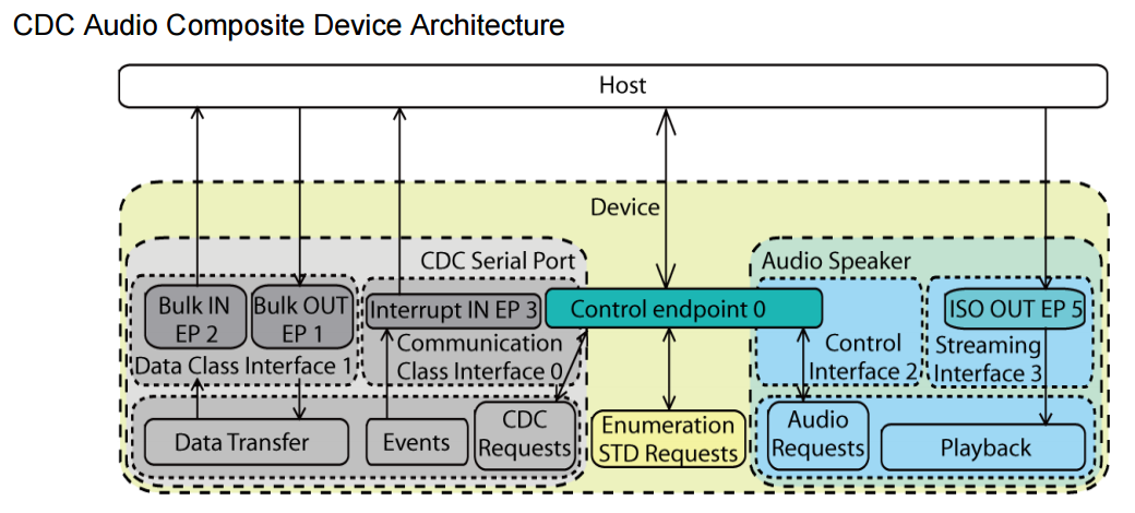
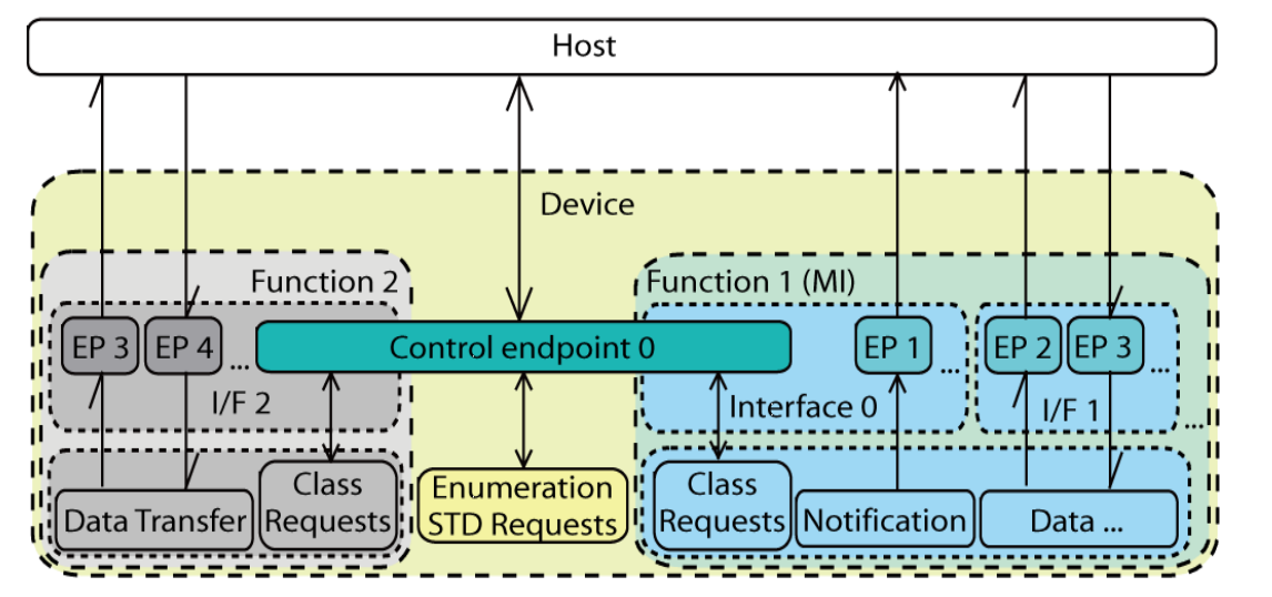
3.2.2.2 Composite with MULTI-interface functions
This kind of composite device includes the functions that are composed of more than one interface,
such as CDC class function, Audio Class function, etc..
The default endpoint (endpoint 0) is usually shared by single-interface-function and the control interface of the multi-interface-function.
There may be other endpoints such as an interrupt IN endpoint for CDC in the control interface for the function to accept control commands or update status.
The interface and endpoint settings are function specific.
The multi-interface function also needs a Interface Association Descriptor (IAD, See Section 3.2.4.1 on page 6) to associate its interfaces.
Figure 3-2. USB Composite Device with MULTI-interface-functions
3.2.3 Endpoints
Excluding the default endpoint, composite devices shall declare a number of endpoints equal to the sum of the number of endpoint required for individual function.
E.g., a composite with HID+CDC needs six endpoint descriptors (Section 4.7.3 on page 15), while HID+MSD (Section 4.7.1 on page 13) only needs five.
Endpoint 0 (default endpoint) is used for standard, class-specific and vendor-specific requests, depending on the implementation of the functions inside.
It can be used to operate on any interface for any device function.
The other endpoints are function-specific, their usage is defined by the class of the function or defined by the vendor.
Figure 3-1 and Figure 3-2 are examples for the composite device architecture with two device functions.
Figure 3-3. USB composite composition
3.2.3.1 Interface & Endpoints compositions for AT91 chip
Since the number of endpoints and the endpoint fifo size is based on hardware,
the assignment of the endpoints should be arranged carefully.
Here are some examples on the endpoint allocation for AT91SAM7SE chip,
since it has 7 endpoints to use.
Please refer to the AT91SAM product datasheet to get the number and the size of endpoints.
Generally, ISO endpoints should be considered firstly, because they always require large FIFO size and double buffer;
the BULK endpoints come the second, which only require a double buffer with transfer speed considered;
the last ones are the Interrupt endpoints, which only require a small FIFO and the lowest speed.
Please refer to the Ping-pong mechanism in the USB device section of the AT91SAM product datasheet.
• HID: For HID device function, only two interrupt endpoints are needed, and since the size is small and speed is low, its endpoints are considered as the lowest priority.
• MSD: For MSD device function, the high speed transaction, two endpoints, bulk transfer, double/triple bank for performance.
• Audio: For Audio device function, the endpoint size should be larger than the audio frame size (here the size is 192 bytes),
more than one endpoint, isochronous transfer and at least double bank.
• CDC: CDC needs three endpoints excluding the default endpoint to work.
Two Bulk endpoints and one Interrupt endpoint. So dual-CDC device will occupy 7 endpoints.
The interrupt endpoints can be assigned to single-buffered endpoints.
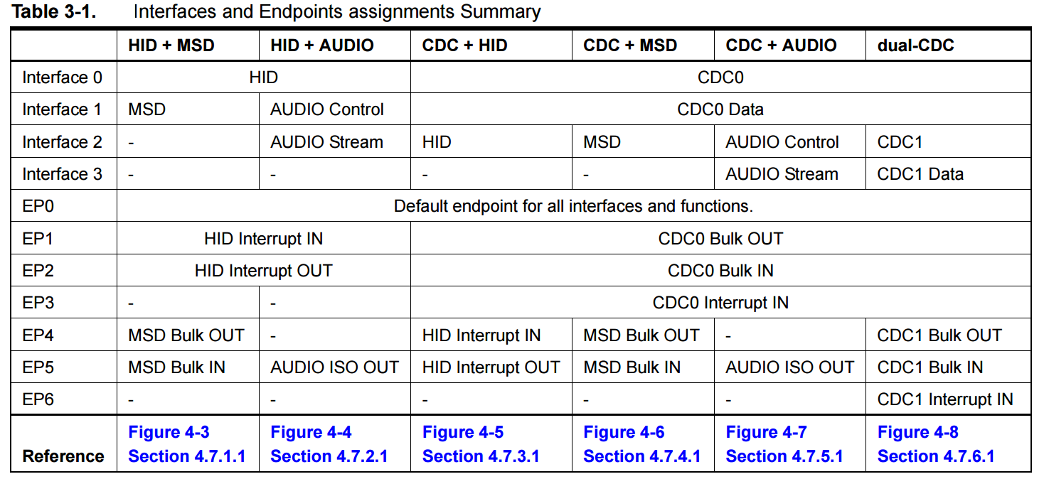
3.2.3.2 Composite Composition Summary
The following is a summary of the interfaces and endpoints assigned.
You can also find reference descriptions and figures in the following sections.
Table 3-1. Interfaces and Endpoints assignments Summary
3.2.4 Specific Descriptors
Since the composite is not for specific class, most of the descriptors for functions are defined in the included class related specifications.
Only one descriptor is necessary to define a multi-interface function:
the Interface Association Descriptor (IAD).
3.2.4.1 Interface Association Descriptor
The Interface Association Descriptor (IAD) is a new standard descriptor defined in USB Engineering Change Notice,
to allow a device to describe which interfaces are associated with the same device function.
This allows the Operation System to bind all of the appropriate interfaces to the same driver instance for the function.
Please see USB ENGINEERING CHANGE NOTICE (Title: Interface Association Descriptors) for detailed information.
The IAD is used to describe that two or more interfaces are associated to the same function.
The ‘association’ includes two or more interfaces and all of their alternative setting interfaces.
A device must use an IAD for each multi-interfaced device function.
An IAD is always returned as part of the configuration information returned by a GetConfigurationDescriptor request.
It must be located before the interface descriptors (including all alternate settings) for the interfaces it associates with.
All of the interface numbers in a particular set of associated interfaces must be contiguous.
Table 3-2 shows the standard interface association descriptor includes function

3.2.5 Specific Requests
No special request is used for a composite device, all requests are defined by the device function that is integrated.
3.3 Host Drivers
Usually the Operating System supports the composite device via two part of drivers - composite driver and the function drivers depending
on the functions that are integrated.
The OS will recognize the USB device as a composite device first then distinguish the included functions and install their driver modules one by one.
Then the functions will appear as normal separated devices for OS to access.
Most OSs now include generic drivers for a wide variety of USB classes.
This makes developing a function device simpler, since the host complexity is now handled by the OS.
Manufacturers can thus concentrate on the device itself, not on developing specific host drivers.
As described before in Section 3.2.4.1 note, the IAD of multi-interface USB devices is a new feature,
there may be issues about how existing USB OS implementations will support devices with IAD.
For Linux®, it is supported now.
For Windows you can refer to Support for USB Interface Association Descriptor in Windows, but patches may needed,
only Windows XP with some hot fix or service pack 3 or later updates fully support this feature now.
Here is a brief list of the various function implementations supported by several OSs
(for CDC maybe additional .inf file is required to install the device but the driver files themselves are from windows source disk):
• Windows (see Windows Supported USB Classes for more)
– MSD: USB Storage disks
– HID: USB Keyboard, Mouse, etc.
– Audio: USB Desktop speaker, recorder.
– CDC: Abstract Control Model, Remote NDIS ...
• Linux (see Linux Device Driver Support for more)
– MSD: USB Storage disks
– HID: USB Keyboard, Mouse, etc.
– CDC: Abstract Control Model
– CDC: Ethernet Model Please refer to the sections about the functions or the class implement application notes for details about the OS compatibility on the device driver.