hbot固件配置
又入了一台打印机,171到手,本来之前有更好的,无奈别人下手太快,只剩这台了。
175x135x180的样子。
创客的板,还带16g的闪迪内存卡,看到那会儿感觉赚大了!
拿到的时候不少螺丝松的,有的打印件也裂口了,拧紧螺丝,调平后打了打感觉操作很多不习惯,
连上电脑看固件原来是marlin1.0的!上github下载了1.19固件,网上似乎没有找到关于hbot的配置贴,
反正以前琢磨过不少次,直接上configuration.h 凭借经验改了改,基本能用了。之后有待调试。

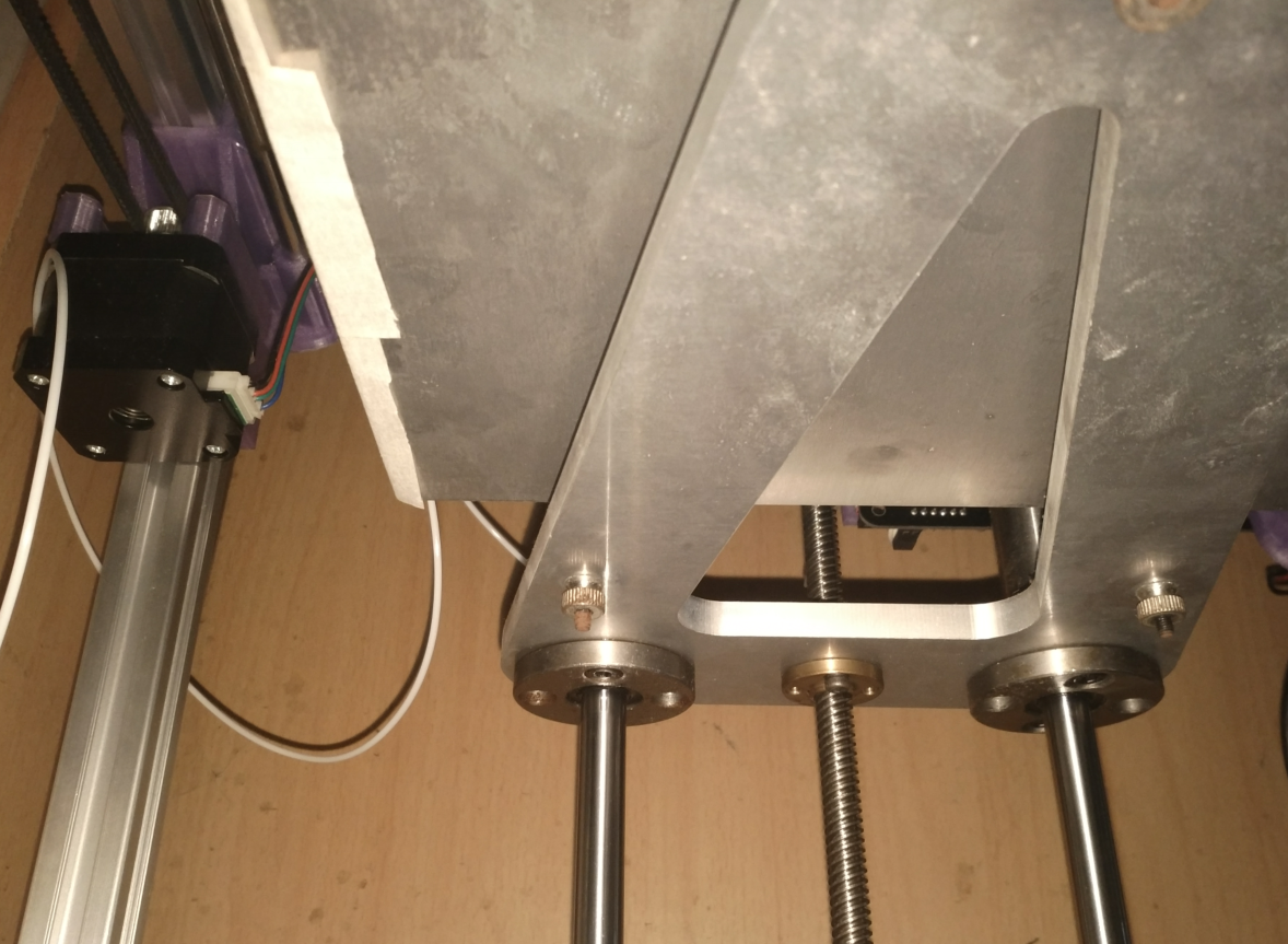
这个平台用料很足,3点很方便调平,拧几下螺丝就解决了
   1 /**
   2  * Marlin 3D Printer Firmware
   3  * Copyright (C) 2016 MarlinFirmware [https://github.com/MarlinFirmware/Marlin]
   4  *
   5  * Based on Sprinter and grbl.
   6  * Copyright (C) 2011 Camiel Gubbels / Erik van der Zalm
   7  *
   8  * This program is free software: you can redistribute it and/or modify
   9  * it under the terms of the GNU General Public License as published by
  10  * the Free Software Foundation, either version 3 of the License, or
  11  * (at your option) any later version.
  12  *
  13  * This program is distributed in the hope that it will be useful,
  14  * but WITHOUT ANY WARRANTY; without even the implied warranty of
  15  * MERCHANTABILITY or FITNESS FOR A PARTICULAR PURPOSE.  See the
  16  * GNU General Public License for more details.
  17  *
  18  * You should have received a copy of the GNU General Public License
  19  * along with this program.  If not, see <http://www.gnu.org/licenses/>.
  20  *
  21  */
  22
  23 /**
  24  * Configuration.h
  25  *
  26  * Basic settings such as:
  27  *
  28  * - Type of electronics
  29  * - Type of temperature sensor
  30  * - Printer geometry
  31  * - Endstop configuration
  32  * - LCD controller
  33  * - Extra features
  34  *
  35  * Advanced settings can be found in Configuration_adv.h
  36  *
  37  */
  38 #ifndef CONFIGURATION_H
  39 #define CONFIGURATION_H
  40 #define CONFIGURATION_H_VERSION 010109
  41
  42 //===========================================================================
  43 //============================= Getting Started =============================
  44 //===========================================================================
  45
  46 /**
  47  * Here are some standard links for getting your machine calibrated:
  48  *
  49  * http://reprap.org/wiki/Calibration
  50  * http://youtu.be/wAL9d7FgInk
  51  * http://calculator.josefprusa.cz
  52  * http://reprap.org/wiki/Triffid_Hunter%27s_Calibration_Guide
  53  * http://www.thingiverse.com/thing:5573
  54  * https://sites.google.com/site/repraplogphase/calibration-of-your-reprap
  55  * http://www.thingiverse.com/thing:298812
  56  */
  57
  58 //===========================================================================
  59 //============================= DELTA Printer ===============================
  60 //===========================================================================
  61 // For a Delta printer start with one of the configuration files in the
  62 // example_configurations/delta directory and customize for your machine.
  63 //
  64
  65 //===========================================================================
  66 //============================= SCARA Printer ===============================
  67 //===========================================================================
  68 // For a SCARA printer start with the configuration files in
  69 // example_configurations/SCARA and customize for your machine.
  70 //
  71
  72 // @section info
  73
  74 // User-specified version info of this build to display in [Pronterface, etc] terminal window during
  75 // startup. Implementation of an idea by Prof Braino to inform user that any changes made to this
  76 // build by the user have been successfully uploaded into firmware.
  77 #define STRING_CONFIG_H_AUTHOR "(none, default config)" // Who made the changes.
  78 #define SHOW_BOOTSCREEN
  79 #define STRING_SPLASH_LINE1 SHORT_BUILD_VERSION // will be shown during bootup in line 1
  80 #define STRING_SPLASH_LINE2 WEBSITE_URL         // will be shown during bootup in line 2
  81
  82 /**
  83  * *** VENDORS PLEASE READ ***
  84  *
  85  * Marlin allows you to add a custom boot image for Graphical LCDs.
  86  * With this option Marlin will first show your custom screen followed
  87  * by the standard Marlin logo with version number and web URL.
  88  *
  89  * We encourage you to take advantage of this new feature and we also
  90  * respectfully request that you retain the unmodified Marlin boot screen.
  91  */
  92
  93 // Enable to show the bitmap in Marlin/_Bootscreen.h on startup.
  94 //#define SHOW_CUSTOM_BOOTSCREEN
  95
  96 // Enable to show the bitmap in Marlin/_Statusscreen.h on the status screen.
  97 //#define CUSTOM_STATUS_SCREEN_IMAGE
  98
  99 // @section machine
 100
 101 /**
 102  * Select the serial port on the board to use for communication with the host.
 103  * This allows the connection of wireless adapters (for instance) to non-default port pins.
 104  * Serial port 0 is always used by the Arduino bootloader regardless of this setting.
 105  *
 106  * :[0, 1, 2, 3, 4, 5, 6, 7]
 107  */
 108 #define SERIAL_PORT 0
 109
 110 /**
 111  * This setting determines the communication speed of the printer.
 112  *
 113  * 250000 works in most cases, but you might try a lower speed if
 114  * you commonly experience drop-outs during host printing.
 115  * You may try up to 1000000 to speed up SD file transfer.
 116  *
 117  * :[2400, 9600, 19200, 38400, 57600, 115200, 250000, 500000, 1000000]
 118  */
 119 #define BAUDRATE 250000
 120
 121 // Enable the Bluetooth serial interface on AT90USB devices
 122 //#define BLUETOOTH
 123
 124 // The following define selects which electronics board you have.
 125 // Please choose the name from boards.h that matches your setup
 126 #ifndef MOTHERBOARD
 127   #define MOTHERBOARD BOARD_MKS_BASE //******changeded
 128 #endif
 129
 130 // Optional custom name for your RepStrap or other custom machine
 131 // Displayed in the LCD "Ready" message
 132 //#define CUSTOM_MACHINE_NAME "3D Printer"
 133
 134 // Define this to set a unique identifier for this printer, (Used by some programs to differentiate between machines)
 135 // You can use an online service to generate a random UUID. (eg http://www.uuidgenerator.net/version4)
 136 //#define MACHINE_UUID "00000000-0000-0000-0000-000000000000"
 137
 138 // @section extruder
 139
 140 // This defines the number of extruders
 141 // :[1, 2, 3, 4, 5]
 142 #define EXTRUDERS 1
 143
 144 // Generally expected filament diameter (1.75, 2.85, 3.0, ...). Used for Volumetric, Filament Width Sensor, etc.
 145 #define DEFAULT_NOMINAL_FILAMENT_DIA 1.75  //*****changeded
 146
 147 // For Cyclops or any "multi-extruder" that shares a single nozzle.
 148 //#define SINGLENOZZLE
 149
 150 /**
 151  * Pr暖拧a MK2 Single Nozzle Multi-Material Multiplexer, and variants.
 152  *
 153  * This device allows one stepper driver on a control board to drive
 154  * two to eight stepper motors, one at a time, in a manner suitable
 155  * for extruders.
 156  *
 157  * This option only allows the multiplexer to switch on tool-change.
 158  * Additional options to configure custom E moves are pending.
 159  */
 160 //#define MK2_MULTIPLEXER
 161 #if ENABLED(MK2_MULTIPLEXER)
 162   // Override the default DIO selector pins here, if needed.
 163   // Some pins files may provide defaults for these pins.
 164   //#define E_MUX0_PIN 40  // Always Required
 165   //#define E_MUX1_PIN 42  // Needed for 3 to 8 steppers
 166   //#define E_MUX2_PIN 44  // Needed for 5 to 8 steppers
 167 #endif
 168
 169 // A dual extruder that uses a single stepper motor
 170 //#define SWITCHING_EXTRUDER
 171 #if ENABLED(SWITCHING_EXTRUDER)
 172   #define SWITCHING_EXTRUDER_SERVO_NR 0
 173   #define SWITCHING_EXTRUDER_SERVO_ANGLES { 0, 90 } // Angles for E0, E1[, E2, E3]
 174   #if EXTRUDERS > 3
 175     #define SWITCHING_EXTRUDER_E23_SERVO_NR 1
 176   #endif
 177 #endif
 178
 179 // A dual-nozzle that uses a servomotor to raise/lower one of the nozzles
 180 //#define SWITCHING_NOZZLE
 181 #if ENABLED(SWITCHING_NOZZLE)
 182   #define SWITCHING_NOZZLE_SERVO_NR 0
 183   #define SWITCHING_NOZZLE_SERVO_ANGLES { 0, 90 }   // Angles for E0, E1
 184   //#define HOTEND_OFFSET_Z { 0.0, 0.0 }
 185 #endif
 186
 187 /**
 188  * Two separate X-carriages with extruders that connect to a moving part
 189  * via a magnetic docking mechanism. Requires SOL1_PIN and SOL2_PIN.
 190  */
 191 //#define PARKING_EXTRUDER
 192 #if ENABLED(PARKING_EXTRUDER)
 193   #define PARKING_EXTRUDER_SOLENOIDS_INVERT           // If enabled, the solenoid is NOT magnetized with applied voltage
 194   #define PARKING_EXTRUDER_SOLENOIDS_PINS_ACTIVE LOW  // LOW or HIGH pin signal energizes the coil
 195   #define PARKING_EXTRUDER_SOLENOIDS_DELAY 250        // Delay (ms) for magnetic field. No delay if 0 or not defined.
 196   #define PARKING_EXTRUDER_PARKING_X { -78, 184 }     // X positions for parking the extruders
 197   #define PARKING_EXTRUDER_GRAB_DISTANCE 1            // mm to move beyond the parking point to grab the extruder
 198   #define PARKING_EXTRUDER_SECURITY_RAISE 5           // Z-raise before parking
 199   #define HOTEND_OFFSET_Z { 0.0, 1.3 }                // Z-offsets of the two hotends. The first must be 0.
 200 #endif
 201
 202 /**
 203  * "Mixing Extruder"
 204  *   - Adds a new code, M165, to set the current mix factors.
 205  *   - Extends the stepping routines to move multiple steppers in proportion to the mix.
 206  *   - Optional support for Repetier Firmware M163, M164, and virtual extruder.
 207  *   - This implementation supports only a single extruder.
 208  *   - Enable DIRECT_MIXING_IN_G1 for Pia Taubert's reference implementation
 209  */
 210 //#define MIXING_EXTRUDER
 211 #if ENABLED(MIXING_EXTRUDER)
 212   #define MIXING_STEPPERS 2        // Number of steppers in your mixing extruder
 213   #define MIXING_VIRTUAL_TOOLS 16  // Use the Virtual Tool method with M163 and M164
 214   //#define DIRECT_MIXING_IN_G1    // Allow ABCDHI mix factors in G1 movement commands
 215 #endif
 216
 217 // Offset of the extruders (uncomment if using more than one and relying on firmware to position when changing).
 218 // The offset has to be X=0, Y=0 for the extruder 0 hotend (default extruder).
 219 // For the other hotends it is their distance from the extruder 0 hotend.
 220 //#define HOTEND_OFFSET_X {0.0, 20.00} // (in mm) for each extruder, offset of the hotend on the X axis
 221 //#define HOTEND_OFFSET_Y {0.0, 5.00}  // (in mm) for each extruder, offset of the hotend on the Y axis
 222
 223 // @section machine
 224
 225 /**
 226  * Select your power supply here. Use 0 if you haven't connected the PS_ON_PIN
 227  *
 228  * 0 = No Power Switch
 229  * 1 = ATX
 230  * 2 = X-Box 360 203Watts (the blue wire connected to PS_ON and the red wire to VCC)
 231  *
 232  * :{ 0:'No power switch', 1:'ATX', 2:'X-Box 360' }
 233  */
 234 #define POWER_SUPPLY 0
 235
 236 #if POWER_SUPPLY > 0
 237   // Enable this option to leave the PSU off at startup.
 238   // Power to steppers and heaters will need to be turned on with M80.
 239   //#define PS_DEFAULT_OFF
 240
 241   //#define AUTO_POWER_CONTROL        // Enable automatic control of the PS_ON pin
 242   #if ENABLED(AUTO_POWER_CONTROL)
 243     #define AUTO_POWER_FANS           // Turn on PSU if fans need power
 244     #define AUTO_POWER_E_FANS
 245     #define AUTO_POWER_CONTROLLERFAN
 246     #define POWER_TIMEOUT 30
 247   #endif
 248
 249 #endif
 250
 251 // @section temperature
 252
 253 //===========================================================================
 254 //============================= Thermal Settings ============================
 255 //===========================================================================
 256
 257 /**
 258  * --NORMAL IS 4.7kohm PULLUP!-- 1kohm pullup can be used on hotend sensor, using correct resistor and table
 259  *
 260  * Temperature sensors available:
 261  *
 262  *    -4 : thermocouple with AD8495
 263  *    -3 : thermocouple with MAX31855 (only for sensor 0)
 264  *    -2 : thermocouple with MAX6675 (only for sensor 0)
 265  *    -1 : thermocouple with AD595
 266  *     0 : not used
 267  *     1 : 100k thermistor - best choice for EPCOS 100k (4.7k pullup)
 268  *     2 : 200k thermistor - ATC Semitec 204GT-2 (4.7k pullup)
 269  *     3 : Mendel-parts thermistor (4.7k pullup)
 270  *     4 : 10k thermistor !! do not use it for a hotend. It gives bad resolution at high temp. !!
 271  *     5 : 100K thermistor - ATC Semitec 104GT-2/104NT-4-R025H42G (Used in ParCan & J-Head) (4.7k pullup)
 272  *   501 : 100K Zonestar (Tronxy X3A) Thermistor
 273  *     6 : 100k EPCOS - Not as accurate as table 1 (created using a fluke thermocouple) (4.7k pullup)
 274  *     7 : 100k Honeywell thermistor 135-104LAG-J01 (4.7k pullup)
 275  *    71 : 100k Honeywell thermistor 135-104LAF-J01 (4.7k pullup)
 276  *     8 : 100k 0603 SMD Vishay NTCS0603E3104FXT (4.7k pullup)
 277  *     9 : 100k GE Sensing AL03006-58.2K-97-G1 (4.7k pullup)
 278  *    10 : 100k RS thermistor 198-961 (4.7k pullup)
 279  *    11 : 100k beta 3950 1% thermistor (4.7k pullup)
 280  *    12 : 100k 0603 SMD Vishay NTCS0603E3104FXT (4.7k pullup) (calibrated for Makibox hot bed)
 281  *    13 : 100k Hisens 3950  1% up to 300掳C for hotend "Simple ONE " & "Hotend "All In ONE"
 282  *    15 : 100k thermistor calibration for JGAurora A5 hotend
 283  *    20 : the PT100 circuit found in the Ultimainboard V2.x
 284  *    60 : 100k Maker's Tool Works Kapton Bed Thermistor beta=3950
 285  *    66 : 4.7M High Temperature thermistor from Dyze Design
 286  *    70 : the 100K thermistor found in the bq Hephestos 2
 287  *    75 : 100k Generic Silicon Heat Pad with NTC 100K MGB18-104F39050L32 thermistor
 288  *
 289  *       1k ohm pullup tables - This is atypical, and requires changing out the 4.7k pullup for 1k.
 290  *                              (but gives greater accuracy and more stable PID)
 291  *    51 : 100k thermistor - EPCOS (1k pullup)
 292  *    52 : 200k thermistor - ATC Semitec 204GT-2 (1k pullup)
 293  *    55 : 100k thermistor - ATC Semitec 104GT-2 (Used in ParCan & J-Head) (1k pullup)
 294  *
 295  *  1047 : Pt1000 with 4k7 pullup
 296  *  1010 : Pt1000 with 1k pullup (non standard)
 297  *   147 : Pt100 with 4k7 pullup
 298  *   110 : Pt100 with 1k pullup (non standard)
 299  *
 300  *         Use these for Testing or Development purposes. NEVER for production machine.
 301  *   998 : Dummy Table that ALWAYS reads 25掳C or the temperature defined below.
 302  *   999 : Dummy Table that ALWAYS reads 100掳C or the temperature defined below.
 303  *
 304  * :{ '0': "Not used", '1':"100k / 4.7k - EPCOS", '2':"200k / 4.7k - ATC Semitec 204GT-2", '3':"Mendel-parts / 4.7k", '4':"10k !! do not use for a hotend. Bad resolution at high temp. !!", '5':"100K / 4.7k - ATC Semitec 104GT-2 (Used in ParCan & J-Head)", '501':"100K Zonestar (Tronxy X3A)", '6':"100k / 4.7k EPCOS - Not as accurate as Table 1", '7':"100k / 4.7k Honeywell 135-104LAG-J01", '8':"100k / 4.7k 0603 SMD Vishay NTCS0603E3104FXT", '9':"100k / 4.7k GE Sensing AL03006-58.2K-97-G1", '10':"100k / 4.7k RS 198-961", '11':"100k / 4.7k beta 3950 1%", '12':"100k / 4.7k 0603 SMD Vishay NTCS0603E3104FXT (calibrated for Makibox hot bed)", '13':"100k Hisens 3950  1% up to 300掳C for hotend 'Simple ONE ' & hotend 'All In ONE'", '20':"PT100 (Ultimainboard V2.x)", '51':"100k / 1k - EPCOS", '52':"200k / 1k - ATC Semitec 204GT-2", '55':"100k / 1k - ATC Semitec 104GT-2 (Used in ParCan & J-Head)", '60':"100k Maker's Tool Works Kapton Bed Thermistor beta=3950", '66':"Dyze Design 4.7M High Temperature thermistor", '70':"the 100K thermistor found in the bq Hephestos 2", '71':"100k / 4.7k Honeywell 135-104LAF-J01", '147':"Pt100 / 4.7k", '1047':"Pt1000 / 4.7k", '110':"Pt100 / 1k (non-standard)", '1010':"Pt1000 / 1k (non standard)", '-4':"Thermocouple + AD8495", '-3':"Thermocouple + MAX31855 (only for sensor 0)", '-2':"Thermocouple + MAX6675 (only for sensor 0)", '-1':"Thermocouple + AD595",'998':"Dummy 1", '999':"Dummy 2" }
 305  */
 306 #define TEMP_SENSOR_0 1
 307 #define TEMP_SENSOR_1 0
 308 #define TEMP_SENSOR_2 0
 309 #define TEMP_SENSOR_3 0
 310 #define TEMP_SENSOR_4 0
 311 #define TEMP_SENSOR_BED 0
 312 #define TEMP_SENSOR_CHAMBER 0
 313
 314 // Dummy thermistor constant temperature readings, for use with 998 and 999
 315 #define DUMMY_THERMISTOR_998_VALUE 25
 316 #define DUMMY_THERMISTOR_999_VALUE 100
 317
 318 // Use temp sensor 1 as a redundant sensor with sensor 0. If the readings
 319 // from the two sensors differ too much the print will be aborted.
 320 //#define TEMP_SENSOR_1_AS_REDUNDANT
 321 #define MAX_REDUNDANT_TEMP_SENSOR_DIFF 10
 322
 323 // Extruder temperature must be close to target for this long before M109 returns success
 324 #define TEMP_RESIDENCY_TIME 10  // (seconds)
 325 #define TEMP_HYSTERESIS 3       // (degC) range of +/- temperatures considered "close" to the target one
 326 #define TEMP_WINDOW     1       // (degC) Window around target to start the residency timer x degC early.
 327
 328 // Bed temperature must be close to target for this long before M190 returns success
 329 #define TEMP_BED_RESIDENCY_TIME 10  // (seconds)
 330 #define TEMP_BED_HYSTERESIS 3       // (degC) range of +/- temperatures considered "close" to the target one
 331 #define TEMP_BED_WINDOW     1       // (degC) Window around target to start the residency timer x degC early.
 332
 333 // The minimal temperature defines the temperature below which the heater will not be enabled It is used
 334 // to check that the wiring to the thermistor is not broken.
 335 // Otherwise this would lead to the heater being powered on all the time.
 336 #define HEATER_0_MINTEMP 5
 337 #define HEATER_1_MINTEMP 5
 338 #define HEATER_2_MINTEMP 5
 339 #define HEATER_3_MINTEMP 5
 340 #define HEATER_4_MINTEMP 5
 341 #define BED_MINTEMP 5
 342
 343 // When temperature exceeds max temp, your heater will be switched off.
 344 // This feature exists to protect your hotend from overheating accidentally, but *NOT* from thermistor short/failure!
 345 // You should use MINTEMP for thermistor short/failure protection.
 346 #define HEATER_0_MAXTEMP 275
 347 #define HEATER_1_MAXTEMP 275
 348 #define HEATER_2_MAXTEMP 275
 349 #define HEATER_3_MAXTEMP 275
 350 #define HEATER_4_MAXTEMP 275
 351 #define BED_MAXTEMP 150
 352
 353 //===========================================================================
 354 //============================= PID Settings ================================
 355 //===========================================================================
 356 // PID Tuning Guide here: http://reprap.org/wiki/PID_Tuning
 357
 358 // Comment the following line to disable PID and enable bang-bang.
 359 #define PIDTEMP
 360 #define BANG_MAX 255     // Limits current to nozzle while in bang-bang mode; 255=full current
 361 #define PID_MAX BANG_MAX // Limits current to nozzle while PID is active (see PID_FUNCTIONAL_RANGE below); 255=full current
 362 #define PID_K1 0.95      // Smoothing factor within any PID loop
 363 #if ENABLED(PIDTEMP)
 364   //#define PID_AUTOTUNE_MENU // Add PID Autotune to the LCD "Temperature" menu to run M303 and apply the result.
 365   //#define PID_DEBUG // Sends debug data to the serial port.
 366   //#define PID_OPENLOOP 1 // Puts PID in open loop. M104/M140 sets the output power from 0 to PID_MAX
 367   //#define SLOW_PWM_HEATERS // PWM with very low frequency (roughly 0.125Hz=8s) and minimum state time of approximately 1s useful for heaters driven by a relay
 368   //#define PID_PARAMS_PER_HOTEND // Uses separate PID parameters for each extruder (useful for mismatched extruders)
 369                                   // Set/get with gcode: M301 E[extruder number, 0-2]
 370   #define PID_FUNCTIONAL_RANGE 10 // If the temperature difference between the target temperature and the actual temperature
 371                                   // is more than PID_FUNCTIONAL_RANGE then the PID will be shut off and the heater will be set to min/max.
 372
 373   // If you are using a pre-configured hotend then you can use one of the value sets by uncommenting it
 374
 375   // Ultimaker
 376   #define DEFAULT_Kp 22.2
 377   #define DEFAULT_Ki 1.08
 378   #define DEFAULT_Kd 114
 379
 380   // MakerGear
 381   //#define DEFAULT_Kp 7.0
 382   //#define DEFAULT_Ki 0.1
 383   //#define DEFAULT_Kd 12
 384
 385   // Mendel Parts V9 on 12V
 386   //#define DEFAULT_Kp 63.0
 387   //#define DEFAULT_Ki 2.25
 388   //#define DEFAULT_Kd 440
 389
 390 #endif // PIDTEMP
 391
 392 //===========================================================================
 393 //============================= PID > Bed Temperature Control ===============
 394 //===========================================================================
 395
 396 /**
 397  * PID Bed Heating
 398  *
 399  * If this option is enabled set PID constants below.
 400  * If this option is disabled, bang-bang will be used and BED_LIMIT_SWITCHING will enable hysteresis.
 401  *
 402  * The PID frequency will be the same as the extruder PWM.
 403  * If PID_dT is the default, and correct for the hardware/configuration, that means 7.689Hz,
 404  * which is fine for driving a square wave into a resistive load and does not significantly
 405  * impact FET heating. This also works fine on a Fotek SSR-10DA Solid State Relay into a 250W
 406  * heater. If your configuration is significantly different than this and you don't understand
 407  * the issues involved, don't use bed PID until someone else verifies that your hardware works.
 408  */
 409 //#define PIDTEMPBED
 410
 411 //#define BED_LIMIT_SWITCHING
 412
 413 /**
 414  * Max Bed Power
 415  * Applies to all forms of bed control (PID, bang-bang, and bang-bang with hysteresis).
 416  * When set to any value below 255, enables a form of PWM to the bed that acts like a divider
 417  * so don't use it unless you are OK with PWM on your bed. (See the comment on enabling PIDTEMPBED)
 418  */
 419 #define MAX_BED_POWER 255 // limits duty cycle to bed; 255=full current
 420
 421 #if ENABLED(PIDTEMPBED)
 422
 423   //#define PID_BED_DEBUG // Sends debug data to the serial port.
 424
 425   //120V 250W silicone heater into 4mm borosilicate (MendelMax 1.5+)
 426   //from FOPDT model - kp=.39 Tp=405 Tdead=66, Tc set to 79.2, aggressive factor of .15 (vs .1, 1, 10)
 427   #define DEFAULT_bedKp 10.00
 428   #define DEFAULT_bedKi .023
 429   #define DEFAULT_bedKd 305.4
 430
 431   //120V 250W silicone heater into 4mm borosilicate (MendelMax 1.5+)
 432   //from pidautotune
 433   //#define DEFAULT_bedKp 97.1
 434   //#define DEFAULT_bedKi 1.41
 435   //#define DEFAULT_bedKd 1675.16
 436
 437   // FIND YOUR OWN: "M303 E-1 C8 S90" to run autotune on the bed at 90 degreesC for 8 cycles.
 438 #endif // PIDTEMPBED
 439
 440 // @section extruder
 441
 442 /**
 443  * Prevent extrusion if the temperature is below EXTRUDE_MINTEMP.
 444  * Add M302 to set the minimum extrusion temperature and/or turn
 445  * cold extrusion prevention on and off.
 446  *
 447  * *** IT IS HIGHLY RECOMMENDED TO LEAVE THIS OPTION ENABLED! ***
 448  */
 449 #define PREVENT_COLD_EXTRUSION
 450 #define EXTRUDE_MINTEMP 170
 451
 452 /**
 453  * Prevent a single extrusion longer than EXTRUDE_MAXLENGTH.
 454  * Note: For Bowden Extruders make this large enough to allow load/unload.
 455  */
 456 #define PREVENT_LENGTHY_EXTRUDE
 457 #define EXTRUDE_MAXLENGTH 200
 458
 459 //===========================================================================
 460 //======================== Thermal Runaway Protection =======================
 461 //===========================================================================
 462
 463 /**
 464  * Thermal Protection provides additional protection to your printer from damage
 465  * and fire. Marlin always includes safe min and max temperature ranges which
 466  * protect against a broken or disconnected thermistor wire.
 467  *
 468  * The issue: If a thermistor falls out, it will report the much lower
 469  * temperature of the air in the room, and the the firmware will keep
 470  * the heater on.
 471  *
 472  * If you get "Thermal Runaway" or "Heating failed" errors the
 473  * details can be tuned in Configuration_adv.h
 474  */
 475
 476 #define THERMAL_PROTECTION_HOTENDS // Enable thermal protection for all extruders
 477 #define THERMAL_PROTECTION_BED     // Enable thermal protection for the heated bed
 478
 479 //===========================================================================
 480 //============================= Mechanical Settings =========================
 481 //===========================================================================
 482
 483 // @section machine
 484
 485 // Uncomment one of these options to enable CoreXY, CoreXZ, or CoreYZ kinematics
 486 // either in the usual order or reversed
 487 //#define COREXY    //*****changeded
 488 //#define COREXZ
 489 //#define COREYZ
 490 #define COREYX
 491 //#define COREZX
 492 //#define COREZY
 493
 494 //===========================================================================
 495 //============================== Endstop Settings ===========================
 496 //===========================================================================
 497
 498 // @section homing
 499
 500 // Specify here all the endstop connectors that are connected to any endstop or probe.
 501 // Almost all printers will be using one per axis. Probes will use one or more of the
 502 // extra connectors. Leave undefined any used for non-endstop and non-probe purposes.
 503 #define USE_XMIN_PLUG
 504 #define USE_YMIN_PLUG
 505 #define USE_ZMIN_PLUG
 506 //#define USE_XMAX_PLUG
 507 //#define USE_YMAX_PLUG
 508 //#define USE_ZMAX_PLUG
 509
 510 // Enable pullup for all endstops to prevent a floating state
 511 #define ENDSTOPPULLUPS
 512 #if DISABLED(ENDSTOPPULLUPS)
 513   // Disable ENDSTOPPULLUPS to set pullups individually
 514   //#define ENDSTOPPULLUP_XMAX
 515   //#define ENDSTOPPULLUP_YMAX
 516   //#define ENDSTOPPULLUP_ZMAX
 517   //#define ENDSTOPPULLUP_XMIN
 518   //#define ENDSTOPPULLUP_YMIN
 519   //#define ENDSTOPPULLUP_ZMIN
 520   //#define ENDSTOPPULLUP_ZMIN_PROBE
 521 #endif
 522
 523 // Mechanical endstop with COM to ground and NC to Signal uses "false" here (most common setup).
 524 #define X_MIN_ENDSTOP_INVERTING true // set to true to invert the logic of the endstop.
 525 #define Y_MIN_ENDSTOP_INVERTING true // set to true to invert the logic of the endstop.
 526 #define Z_MIN_ENDSTOP_INVERTING true // set to true to invert the logic of the endstop.
 527 #define X_MAX_ENDSTOP_INVERTING false // set to true to invert the logic of the endstop.
 528 #define Y_MAX_ENDSTOP_INVERTING false // set to true to invert the logic of the endstop.
 529 #define Z_MAX_ENDSTOP_INVERTING false // set to true to invert the logic of the endstop.
 530 #define Z_MIN_PROBE_ENDSTOP_INVERTING false // set to true to invert the logic of the probe.
 531
 532 /**
 533  * Stepper Drivers
 534  *
 535  * These settings allow Marlin to tune stepper driver timing and enable advanced options for
 536  * stepper drivers that support them. You may also override timing options in Configuration_adv.h.
 537  *
 538  * A4988 is assumed for unspecified drivers.
 539  *
 540  * Options: A4988, DRV8825, LV8729, L6470, TB6560, TB6600, TMC2100,
 541  *          TMC2130, TMC2130_STANDALONE, TMC2208, TMC2208_STANDALONE,
 542  *          TMC26X,  TMC26X_STANDALONE,  TMC2660, TMC2660_STANDALONE,
 543  *          TMC5130, TMC5130_STANDALONE
 544  * :['A4988', 'DRV8825', 'LV8729', 'L6470', 'TB6560', 'TB6600', 'TMC2100', 'TMC2130', 'TMC2130_STANDALONE', 'TMC2208', 'TMC2208_STANDALONE', 'TMC26X', 'TMC26X_STANDALONE', 'TMC2660', 'TMC2660_STANDALONE', 'TMC5130', 'TMC5130_STANDALONE']
 545  */
 546 //#define X_DRIVER_TYPE  A4988
 547 //#define Y_DRIVER_TYPE  A4988
 548 //#define Z_DRIVER_TYPE  A4988
 549 //#define X2_DRIVER_TYPE A4988
 550 //#define Y2_DRIVER_TYPE A4988
 551 //#define Z2_DRIVER_TYPE A4988
 552 //#define E0_DRIVER_TYPE A4988
 553 //#define E1_DRIVER_TYPE A4988
 554 //#define E2_DRIVER_TYPE A4988
 555 //#define E3_DRIVER_TYPE A4988
 556 //#define E4_DRIVER_TYPE A4988
 557
 558 // Enable this feature if all enabled endstop pins are interrupt-capable.
 559 // This will remove the need to poll the interrupt pins, saving many CPU cycles.
 560 //#define ENDSTOP_INTERRUPTS_FEATURE
 561
 562 /**
 563  * Endstop Noise Filter
 564  *
 565  * Enable this option if endstops falsely trigger due to noise.
 566  * NOTE: Enabling this feature means adds an error of +/-0.2mm, so homing
 567  * will end up at a slightly different position on each G28. This will also
 568  * reduce accuracy of some bed probes.
 569  * For mechanical switches, the better approach to reduce noise is to install
 570  * a 100 nanofarads ceramic capacitor in parallel with the switch, making it
 571  * essentially noise-proof without sacrificing accuracy.
 572  * This option also increases MCU load when endstops or the probe are enabled.
 573  * So this is not recommended. USE AT YOUR OWN RISK.
 574  * (This feature is not required for common micro-switches mounted on PCBs
 575  * based on the Makerbot design, since they already include the 100nF capacitor.)
 576  */
 577 //#define ENDSTOP_NOISE_FILTER
 578
 579 //=============================================================================
 580 //============================== Movement Settings ============================
 581 //=============================================================================
 582 // @section motion
 583
 584 /**
 585  * Default Settings
 586  *
 587  * These settings can be reset by M502
 588  *
 589  * Note that if EEPROM is enabled, saved values will override these.
 590  */
 591
 592 /**
 593  * With this option each E stepper can have its own factors for the
 594  * following movement settings. If fewer factors are given than the
 595  * total number of extruders, the last value applies to the rest.
 596  */
 597 //#define DISTINCT_E_FACTORS
 598
 599 /**
 600  * Default Axis Steps Per Unit (steps/mm)
 601  * Override with M92
 602  *                                      X, Y, Z, E0 [, E1[, E2[, E3[, E4]]]]
 603  */
 604 #define DEFAULT_AXIS_STEPS_PER_UNIT   { 80, 80, 400, 94 }//****changeded
 605
 606 /**
 607  * Default Max Feed Rate (mm/s)
 608  * Override with M203
 609  *                                      X, Y, Z, E0 [, E1[, E2[, E3[, E4]]]]
 610  */
 611 #define DEFAULT_MAX_FEEDRATE          { 300, 300, 5, 25 }
 612
 613 /**
 614  * Default Max Acceleration (change/s) change = mm/s
 615  * (Maximum start speed for accelerated moves)
 616  * Override with M201
 617  *                                      X, Y, Z, E0 [, E1[, E2[, E3[, E4]]]]
 618  */
 619 #define DEFAULT_MAX_ACCELERATION      { 3000, 3000, 100, 10000 }
 620
 621 /**
 622  * Default Acceleration (change/s) change = mm/s
 623  * Override with M204
 624  *
 625  *   M204 P    Acceleration
 626  *   M204 R    Retract Acceleration
 627  *   M204 T    Travel Acceleration
 628  */
 629 #define DEFAULT_ACCELERATION          3000    // X, Y, Z and E acceleration for printing moves
 630 #define DEFAULT_RETRACT_ACCELERATION  3000    // E acceleration for retracts
 631 #define DEFAULT_TRAVEL_ACCELERATION   3000    // X, Y, Z acceleration for travel (non printing) moves
 632
 633 /**
 634  * Default Jerk (mm/s)
 635  * Override with M205 X Y Z E
 636  *
 637  * "Jerk" specifies the minimum speed change that requires acceleration.
 638  * When changing speed and direction, if the difference is less than the
 639  * value set here, it may happen instantaneously.
 640  */
 641 #define DEFAULT_XJERK                 10.0
 642 #define DEFAULT_YJERK                 10.0
 643 #define DEFAULT_ZJERK                  0.3
 644 #define DEFAULT_EJERK                  5.0
 645
 646 /**
 647  * S-Curve Acceleration
 648  *
 649  * This option eliminates vibration during printing by fitting a B茅zier
 650  * curve to move acceleration, producing much smoother direction changes.
 651  *
 652  * See https://github.com/synthetos/TinyG/wiki/Jerk-Controlled-Motion-Explained
 653  */
 654 //#define S_CURVE_ACCELERATION
 655
 656 //===========================================================================
 657 //============================= Z Probe Options =============================
 658 //===========================================================================
 659 // @section probes
 660
 661 //
 662 // See http://marlinfw.org/docs/configuration/probes.html
 663 //
 664
 665 /**
 666  * Z_MIN_PROBE_USES_Z_MIN_ENDSTOP_PIN
 667  *
 668  * Enable this option for a probe connected to the Z Min endstop pin.
 669  */
 670 #define Z_MIN_PROBE_USES_Z_MIN_ENDSTOP_PIN
 671
 672 /**
 673  * Z_MIN_PROBE_ENDSTOP
 674  *
 675  * Enable this option for a probe connected to any pin except Z-Min.
 676  * (By default Marlin assumes the Z-Max endstop pin.)
 677  * To use a custom Z Probe pin, set Z_MIN_PROBE_PIN below.
 678  *
 679  *  - The simplest option is to use a free endstop connector.
 680  *  - Use 5V for powered (usually inductive) sensors.
 681  *
 682  *  - RAMPS 1.3/1.4 boards may use the 5V, GND, and Aux4->D32 pin:
 683  *    - For simple switches connect...
 684  *      - normally-closed switches to GND and D32.
 685  *      - normally-open switches to 5V and D32.
 686  *
 687  * WARNING: Setting the wrong pin may have unexpected and potentially
 688  * disastrous consequences. Use with caution and do your homework.
 689  *
 690  */
 691 //#define Z_MIN_PROBE_ENDSTOP
 692
 693 /**
 694  * Probe Type
 695  *
 696  * Allen Key Probes, Servo Probes, Z-Sled Probes, FIX_MOUNTED_PROBE, etc.
 697  * Activate one of these to use Auto Bed Leveling below.
 698  */
 699
 700 /**
 701  * The "Manual Probe" provides a means to do "Auto" Bed Leveling without a probe.
 702  * Use G29 repeatedly, adjusting the Z height at each point with movement commands
 703  * or (with LCD_BED_LEVELING) the LCD controller.
 704  */
 705 //#define PROBE_MANUALLY
 706 //#define MANUAL_PROBE_START_Z 0.2
 707
 708 /**
 709  * A Fix-Mounted Probe either doesn't deploy or needs manual deployment.
 710  *   (e.g., an inductive probe or a nozzle-based probe-switch.)
 711  */
 712 //#define FIX_MOUNTED_PROBE
 713
 714 /**
 715  * Z Servo Probe, such as an endstop switch on a rotating arm.
 716  */
 717 //#define Z_PROBE_SERVO_NR 0   // Defaults to SERVO 0 connector.
 718 //#define Z_SERVO_ANGLES {70,0}  // Z Servo Deploy and Stow angles
 719
 720 /**
 721  * The BLTouch probe uses a Hall effect sensor and emulates a servo.
 722  */
 723 //#define BLTOUCH
 724 #if ENABLED(BLTOUCH)
 725   //#define BLTOUCH_DELAY 375   // (ms) Enable and increase if needed
 726 #endif
 727
 728 /**
 729  * Enable one or more of the following if probing seems unreliable.
 730  * Heaters and/or fans can be disabled during probing to minimize electrical
 731  * noise. A delay can also be added to allow noise and vibration to settle.
 732  * These options are most useful for the BLTouch probe, but may also improve
 733  * readings with inductive probes and piezo sensors.
 734  */
 735 //#define PROBING_HEATERS_OFF       // Turn heaters off when probing
 736 #if ENABLED(PROBING_HEATERS_OFF)
 737   //#define WAIT_FOR_BED_HEATER     // Wait for bed to heat back up between probes (to improve accuracy)
 738 #endif
 739 //#define PROBING_FANS_OFF          // Turn fans off when probing
 740 //#define DELAY_BEFORE_PROBING 200  // (ms) To prevent vibrations from triggering piezo sensors
 741
 742 // A probe that is deployed and stowed with a solenoid pin (SOL1_PIN)
 743 //#define SOLENOID_PROBE
 744
 745 // A sled-mounted probe like those designed by Charles Bell.
 746 //#define Z_PROBE_SLED
 747 //#define SLED_DOCKING_OFFSET 5  // The extra distance the X axis must travel to pickup the sled. 0 should be fine but you can push it further if you'd like.
 748
 749 //
 750 // For Z_PROBE_ALLEN_KEY see the Delta example configurations.
 751 //
 752
 753 /**
 754  *   Z Probe to nozzle (X,Y) offset, relative to (0, 0).
 755  *   X and Y offsets must be integers.
 756  *
 757  *   In the following example the X and Y offsets are both positive:
 758  *   #define X_PROBE_OFFSET_FROM_EXTRUDER 10
 759  *   #define Y_PROBE_OFFSET_FROM_EXTRUDER 10
 760  *
 761  *      +-- BACK ---+
 762  *      |           |
 763  *    L |    (+) P  | R <-- probe (20,20)
 764  *    E |           | I
 765  *    F | (-) N (+) | G <-- nozzle (10,10)
 766  *    T |           | H
 767  *      |    (-)    | T
 768  *      |           |
 769  *      O-- FRONT --+
 770  *    (0,0)
 771  */
 772 #define X_PROBE_OFFSET_FROM_EXTRUDER 10  // X offset: -left  +right  [of the nozzle]
 773 #define Y_PROBE_OFFSET_FROM_EXTRUDER 10  // Y offset: -front +behind [the nozzle]
 774 #define Z_PROBE_OFFSET_FROM_EXTRUDER 0   // Z offset: -below +above  [the nozzle]
 775
 776 // Certain types of probes need to stay away from edges
 777 #define MIN_PROBE_EDGE 10
 778
 779 // X and Y axis travel speed (mm/m) between probes
 780 #define XY_PROBE_SPEED 8000
 781
 782 // Feedrate (mm/m) for the first approach when double-probing (MULTIPLE_PROBING == 2)
 783 #define Z_PROBE_SPEED_FAST HOMING_FEEDRATE_Z
 784
 785 // Feedrate (mm/m) for the "accurate" probe of each point
 786 #define Z_PROBE_SPEED_SLOW (Z_PROBE_SPEED_FAST / 2)
 787
 788 // The number of probes to perform at each point.
 789 //   Set to 2 for a fast/slow probe, using the second probe result.
 790 //   Set to 3 or more for slow probes, averaging the results.
 791 //#define MULTIPLE_PROBING 2
 792
 793 /**
 794  * Z probes require clearance when deploying, stowing, and moving between
 795  * probe points to avoid hitting the bed and other hardware.
 796  * Servo-mounted probes require extra space for the arm to rotate.
 797  * Inductive probes need space to keep from triggering early.
 798  *
 799  * Use these settings to specify the distance (mm) to raise the probe (or
 800  * lower the bed). The values set here apply over and above any (negative)
 801  * probe Z Offset set with Z_PROBE_OFFSET_FROM_EXTRUDER, M851, or the LCD.
 802  * Only integer values >= 1 are valid here.
 803  *
 804  * Example: `M851 Z-5` with a CLEARANCE of 4  =>  9mm from bed to nozzle.
 805  *     But: `M851 Z+1` with a CLEARANCE of 2  =>  2mm from bed to nozzle.
 806  */
 807 #define Z_CLEARANCE_DEPLOY_PROBE   10 // Z Clearance for Deploy/Stow
 808 #define Z_CLEARANCE_BETWEEN_PROBES  5 // Z Clearance between probe points
 809 #define Z_CLEARANCE_MULTI_PROBE     5 // Z Clearance between multiple probes
 810 //#define Z_AFTER_PROBING           5 // Z position after probing is done
 811
 812 #define Z_PROBE_LOW_POINT          -2 // Farthest distance below the trigger-point to go before stopping
 813
 814 // For M851 give a range for adjusting the Z probe offset
 815 #define Z_PROBE_OFFSET_RANGE_MIN -20
 816 #define Z_PROBE_OFFSET_RANGE_MAX 20
 817
 818 // Enable the M48 repeatability test to test probe accuracy
 819 //#define Z_MIN_PROBE_REPEATABILITY_TEST
 820
 821 // For Inverting Stepper Enable Pins (Active Low) use 0, Non Inverting (Active High) use 1
 822 // :{ 0:'Low', 1:'High' }
 823 #define X_ENABLE_ON 0
 824 #define Y_ENABLE_ON 0
 825 #define Z_ENABLE_ON 0
 826 #define E_ENABLE_ON 0 // For all extruders
 827
 828 // Disables axis stepper immediately when it's not being used.
 829 // WARNING: When motors turn off there is a chance of losing position accuracy!
 830 #define DISABLE_X false
 831 #define DISABLE_Y false
 832 #define DISABLE_Z false
 833 // Warn on display about possibly reduced accuracy
 834 //#define DISABLE_REDUCED_ACCURACY_WARNING
 835
 836 // @section extruder
 837
 838 #define DISABLE_E false // For all extruders
 839 #define DISABLE_INACTIVE_EXTRUDER true // Keep only the active extruder enabled.
 840
 841 // @section machine
 842
 843 // Invert the stepper direction. Change (or reverse the motor connector) if an axis goes the wrong way.
 844 #define INVERT_X_DIR false
 845 #define INVERT_Y_DIR true
 846 #define INVERT_Z_DIR false
 847
 848 // @section extruder
 849
 850 // For direct drive extruder v9 set to true, for geared extruder set to false.
 851 #define INVERT_E0_DIR true
 852 #define INVERT_E1_DIR false
 853 #define INVERT_E2_DIR false
 854 #define INVERT_E3_DIR false
 855 #define INVERT_E4_DIR false
 856
 857 // @section homing
 858
 859 //#define NO_MOTION_BEFORE_HOMING  // Inhibit movement until all axes have been homed
 860
 861 //#define UNKNOWN_Z_NO_RAISE // Don't raise Z (lower the bed) if Z is "unknown." For beds that fall when Z is powered off.
 862
 863 //#define Z_HOMING_HEIGHT 4  // (in mm) Minimal z height before homing (G28) for Z clearance above the bed, clamps, ...
 864                              // Be sure you have this distance over your Z_MAX_POS in case.
 865
 866 // Direction of endstops when homing; 1=MAX, -1=MIN
 867 // :[-1,1]
 868 #define X_HOME_DIR -1
 869 #define Y_HOME_DIR -1
 870 #define Z_HOME_DIR -1
 871
 872 // @section machine
 873
 874 // The size of the print bed
 875 #define X_BED_SIZE 175
 876 #define Y_BED_SIZE 135
 877
 878 // Travel limits (mm) after homing, corresponding to endstop positions.
 879 #define X_MIN_POS 0
 880 #define Y_MIN_POS 0
 881 #define Z_MIN_POS 0
 882 #define X_MAX_POS X_BED_SIZE
 883 #define Y_MAX_POS Y_BED_SIZE
 884 #define Z_MAX_POS 170
 885
 886 /**
 887  * Software Endstops
 888  *
 889  * - Prevent moves outside the set machine bounds.
 890  * - Individual axes can be disabled, if desired.
 891  * - X and Y only apply to Cartesian robots.
 892  * - Use 'M211' to set software endstops on/off or report current state
 893  */
 894
 895 // Min software endstops constrain movement within minimum coordinate bounds
 896 #define MIN_SOFTWARE_ENDSTOPS
 897 #if ENABLED(MIN_SOFTWARE_ENDSTOPS)
 898   #define MIN_SOFTWARE_ENDSTOP_X
 899   #define MIN_SOFTWARE_ENDSTOP_Y
 900   #define MIN_SOFTWARE_ENDSTOP_Z
 901 #endif
 902
 903 // Max software endstops constrain movement within maximum coordinate bounds
 904 #define MAX_SOFTWARE_ENDSTOPS
 905 #if ENABLED(MAX_SOFTWARE_ENDSTOPS)
 906   #define MAX_SOFTWARE_ENDSTOP_X
 907   #define MAX_SOFTWARE_ENDSTOP_Y
 908   #define MAX_SOFTWARE_ENDSTOP_Z
 909 #endif
 910
 911 #if ENABLED(MIN_SOFTWARE_ENDSTOPS) || ENABLED(MAX_SOFTWARE_ENDSTOPS)
 912   //#define SOFT_ENDSTOPS_MENU_ITEM  // Enable/Disable software endstops from the LCD
 913 #endif
 914
 915 /**
 916  * Filament Runout Sensors
 917  * Mechanical or opto endstops are used to check for the presence of filament.
 918  *
 919  * RAMPS-based boards use SERVO3_PIN for the first runout sensor.
 920  * For other boards you may need to define FIL_RUNOUT_PIN, FIL_RUNOUT2_PIN, etc.
 921  * By default the firmware assumes HIGH=FILAMENT PRESENT.
 922  */
 923 //#define FILAMENT_RUNOUT_SENSOR
 924 #if ENABLED(FILAMENT_RUNOUT_SENSOR)
 925   #define NUM_RUNOUT_SENSORS   1     // Number of sensors, up to one per extruder. Define a FIL_RUNOUT#_PIN for each.
 926   #define FIL_RUNOUT_INVERTING false // set to true to invert the logic of the sensor.
 927   #define FIL_RUNOUT_PULLUP          // Use internal pullup for filament runout pins.
 928   #define FILAMENT_RUNOUT_SCRIPT "M600"
 929 #endif
 930
 931 //===========================================================================
 932 //=============================== Bed Leveling ==============================
 933 //===========================================================================
 934 // @section calibrate
 935
 936 /**
 937  * Choose one of the options below to enable G29 Bed Leveling. The parameters
 938  * and behavior of G29 will change depending on your selection.
 939  *
 940  *  If using a Probe for Z Homing, enable Z_SAFE_HOMING also!
 941  *
 942  * - AUTO_BED_LEVELING_3POINT
 943  *   Probe 3 arbitrary points on the bed (that aren't collinear)
 944  *   You specify the XY coordinates of all 3 points.
 945  *   The result is a single tilted plane. Best for a flat bed.
 946  *
 947  * - AUTO_BED_LEVELING_LINEAR
 948  *   Probe several points in a grid.
 949  *   You specify the rectangle and the density of sample points.
 950  *   The result is a single tilted plane. Best for a flat bed.
 951  *
 952  * - AUTO_BED_LEVELING_BILINEAR
 953  *   Probe several points in a grid.
 954  *   You specify the rectangle and the density of sample points.
 955  *   The result is a mesh, best for large or uneven beds.
 956  *
 957  * - AUTO_BED_LEVELING_UBL (Unified Bed Leveling)
 958  *   A comprehensive bed leveling system combining the features and benefits
 959  *   of other systems. UBL also includes integrated Mesh Generation, Mesh
 960  *   Validation and Mesh Editing systems.
 961  *
 962  * - MESH_BED_LEVELING
 963  *   Probe a grid manually
 964  *   The result is a mesh, suitable for large or uneven beds. (See BILINEAR.)
 965  *   For machines without a probe, Mesh Bed Leveling provides a method to perform
 966  *   leveling in steps so you can manually adjust the Z height at each grid-point.
 967  *   With an LCD controller the process is guided step-by-step.
 968  */
 969 //#define AUTO_BED_LEVELING_3POINT
 970 //#define AUTO_BED_LEVELING_LINEAR
 971 //#define AUTO_BED_LEVELING_BILINEAR
 972 //#define AUTO_BED_LEVELING_UBL
 973 //#define MESH_BED_LEVELING
 974
 975 /**
 976  * Normally G28 leaves leveling disabled on completion. Enable
 977  * this option to have G28 restore the prior leveling state.
 978  */
 979 //#define RESTORE_LEVELING_AFTER_G28
 980
 981 /**
 982  * Enable detailed logging of G28, G29, M48, etc.
 983  * Turn on with the command 'M111 S32'.
 984  * NOTE: Requires a lot of PROGMEM!
 985  */
 986 //#define DEBUG_LEVELING_FEATURE
 987
 988 #if ENABLED(MESH_BED_LEVELING) || ENABLED(AUTO_BED_LEVELING_BILINEAR) || ENABLED(AUTO_BED_LEVELING_UBL)
 989   // Gradually reduce leveling correction until a set height is reached,
 990   // at which point movement will be level to the machine's XY plane.
 991   // The height can be set with M420 Z<height>
 992   #define ENABLE_LEVELING_FADE_HEIGHT
 993
 994   // For Cartesian machines, instead of dividing moves on mesh boundaries,
 995   // split up moves into short segments like a Delta. This follows the
 996   // contours of the bed more closely than edge-to-edge straight moves.
 997   #define SEGMENT_LEVELED_MOVES
 998   #define LEVELED_SEGMENT_LENGTH 5.0 // (mm) Length of all segments (except the last one)
 999
1000   /**
1001    * Enable the G26 Mesh Validation Pattern tool.
1002    */
1003   //#define G26_MESH_VALIDATION
1004   #if ENABLED(G26_MESH_VALIDATION)
1005     #define MESH_TEST_NOZZLE_SIZE    0.4  // (mm) Diameter of primary nozzle.
1006     #define MESH_TEST_LAYER_HEIGHT   0.2  // (mm) Default layer height for the G26 Mesh Validation Tool.
1007     #define MESH_TEST_HOTEND_TEMP  205.0  // (掳C) Default nozzle temperature for the G26 Mesh Validation Tool.
1008     #define MESH_TEST_BED_TEMP      60.0  // (掳C) Default bed temperature for the G26 Mesh Validation Tool.
1009   #endif
1010
1011 #endif
1012
1013 #if ENABLED(AUTO_BED_LEVELING_LINEAR) || ENABLED(AUTO_BED_LEVELING_BILINEAR)
1014
1015   // Set the number of grid points per dimension.
1016   #define GRID_MAX_POINTS_X 3
1017   #define GRID_MAX_POINTS_Y GRID_MAX_POINTS_X
1018
1019   // Set the boundaries for probing (where the probe can reach).
1020   //#define LEFT_PROBE_BED_POSITION MIN_PROBE_EDGE
1021   //#define RIGHT_PROBE_BED_POSITION (X_BED_SIZE - MIN_PROBE_EDGE)
1022   //#define FRONT_PROBE_BED_POSITION MIN_PROBE_EDGE
1023   //#define BACK_PROBE_BED_POSITION (Y_BED_SIZE - MIN_PROBE_EDGE)
1024
1025   // Probe along the Y axis, advancing X after each column
1026   //#define PROBE_Y_FIRST
1027
1028   #if ENABLED(AUTO_BED_LEVELING_BILINEAR)
1029
1030     // Beyond the probed grid, continue the implied tilt?
1031     // Default is to maintain the height of the nearest edge.
1032     //#define EXTRAPOLATE_BEYOND_GRID
1033
1034     //
1035     // Experimental Subdivision of the grid by Catmull-Rom method.
1036     // Synthesizes intermediate points to produce a more detailed mesh.
1037     //
1038     //#define ABL_BILINEAR_SUBDIVISION
1039     #if ENABLED(ABL_BILINEAR_SUBDIVISION)
1040       // Number of subdivisions between probe points
1041       #define BILINEAR_SUBDIVISIONS 3
1042     #endif
1043
1044   #endif
1045
1046 #elif ENABLED(AUTO_BED_LEVELING_UBL)
1047
1048   //===========================================================================
1049   //========================= Unified Bed Leveling ============================
1050   //===========================================================================
1051
1052   //#define MESH_EDIT_GFX_OVERLAY   // Display a graphics overlay while editing the mesh
1053
1054   #define MESH_INSET 1              // Set Mesh bounds as an inset region of the bed
1055   #define GRID_MAX_POINTS_X 10      // Don't use more than 15 points per axis, implementation limited.
1056   #define GRID_MAX_POINTS_Y GRID_MAX_POINTS_X
1057
1058   #define UBL_MESH_EDIT_MOVES_Z     // Sophisticated users prefer no movement of nozzle
1059   #define UBL_SAVE_ACTIVE_ON_M500   // Save the currently active mesh in the current slot on M500
1060
1061   //#define UBL_Z_RAISE_WHEN_OFF_MESH 2.5 // When the nozzle is off the mesh, this value is used
1062                                           // as the Z-Height correction value.
1063
1064 #elif ENABLED(MESH_BED_LEVELING)
1065
1066   //===========================================================================
1067   //=================================== Mesh ==================================
1068   //===========================================================================
1069
1070   #define MESH_INSET 10          // Set Mesh bounds as an inset region of the bed
1071   #define GRID_MAX_POINTS_X 3    // Don't use more than 7 points per axis, implementation limited.
1072   #define GRID_MAX_POINTS_Y GRID_MAX_POINTS_X
1073
1074   //#define MESH_G28_REST_ORIGIN // After homing all axes ('G28' or 'G28 XYZ') rest Z at Z_MIN_POS
1075
1076 #endif // BED_LEVELING
1077
1078 /**
1079  * Points to probe for all 3-point Leveling procedures.
1080  * Override if the automatically selected points are inadequate.
1081  */
1082 #if ENABLED(AUTO_BED_LEVELING_3POINT) || ENABLED(AUTO_BED_LEVELING_UBL)
1083   //#define PROBE_PT_1_X 15
1084   //#define PROBE_PT_1_Y 180
1085   //#define PROBE_PT_2_X 15
1086   //#define PROBE_PT_2_Y 20
1087   //#define PROBE_PT_3_X 170
1088   //#define PROBE_PT_3_Y 20
1089 #endif
1090
1091 /**
1092  * Add a bed leveling sub-menu for ABL or MBL.
1093  * Include a guided procedure if manual probing is enabled.
1094  */
1095 //#define LCD_BED_LEVELING
1096
1097 #if ENABLED(LCD_BED_LEVELING)
1098   #define MBL_Z_STEP 0.025    // Step size while manually probing Z axis.
1099   #define LCD_PROBE_Z_RANGE 4 // Z Range centered on Z_MIN_POS for LCD Z adjustment
1100 #endif
1101
1102 // Add a menu item to move between bed corners for manual bed adjustment
1103 //#define LEVEL_BED_CORNERS
1104
1105 #if ENABLED(LEVEL_BED_CORNERS)
1106   #define LEVEL_CORNERS_INSET 30    // (mm) An inset for corner leveling
1107   //#define LEVEL_CENTER_TOO        // Move to the center after the last corner
1108 #endif
1109
1110 /**
1111  * Commands to execute at the end of G29 probing.
1112  * Useful to retract or move the Z probe out of the way.
1113  */
1114 //#define Z_PROBE_END_SCRIPT "G1 Z10 F12000\nG1 X15 Y330\nG1 Z0.5\nG1 Z10"
1115
1116
1117 // @section homing
1118
1119 // The center of the bed is at (X=0, Y=0)
1120 //#define BED_CENTER_AT_0_0
1121
1122 // Manually set the home position. Leave these undefined for automatic settings.
1123 // For DELTA this is the top-center of the Cartesian print volume.
1124 //#define MANUAL_X_HOME_POS 0
1125 //#define MANUAL_Y_HOME_POS 0
1126 //#define MANUAL_Z_HOME_POS 0
1127
1128 // Use "Z Safe Homing" to avoid homing with a Z probe outside the bed area.
1129 //
1130 // With this feature enabled:
1131 //
1132 // - Allow Z homing only after X and Y homing AND stepper drivers still enabled.
1133 // - If stepper drivers time out, it will need X and Y homing again before Z homing.
1134 // - Move the Z probe (or nozzle) to a defined XY point before Z Homing when homing all axes (G28).
1135 // - Prevent Z homing when the Z probe is outside bed area.
1136 //
1137 //#define Z_SAFE_HOMING
1138
1139 #if ENABLED(Z_SAFE_HOMING)
1140   #define Z_SAFE_HOMING_X_POINT ((X_BED_SIZE) / 2)    // X point for Z homing when homing all axes (G28).
1141   #define Z_SAFE_HOMING_Y_POINT ((Y_BED_SIZE) / 2)    // Y point for Z homing when homing all axes (G28).
1142 #endif
1143
1144 // Homing speeds (mm/m)
1145 #define HOMING_FEEDRATE_XY (50*60)
1146 #define HOMING_FEEDRATE_Z  (4*60)
1147
1148 // @section calibrate
1149
1150 /**
1151  * Bed Skew Compensation
1152  *
1153  * This feature corrects for misalignment in the XYZ axes.
1154  *
1155  * Take the following steps to get the bed skew in the XY plane:
1156  *  1. Print a test square (e.g., https://www.thingiverse.com/thing:2563185)
1157  *  2. For XY_DIAG_AC measure the diagonal A to C
1158  *  3. For XY_DIAG_BD measure the diagonal B to D
1159  *  4. For XY_SIDE_AD measure the edge A to D
1160  *
1161  * Marlin automatically computes skew factors from these measurements.
1162  * Skew factors may also be computed and set manually:
1163  *
1164  *  - Compute AB     : SQRT(2*AC*AC+2*BD*BD-4*AD*AD)/2
1165  *  - XY_SKEW_FACTOR : TAN(PI/2-ACOS((AC*AC-AB*AB-AD*AD)/(2*AB*AD)))
1166  *
1167  * If desired, follow the same procedure for XZ and YZ.
1168  * Use these diagrams for reference:
1169  *
1170  *    Y                     Z                     Z
1171  *    ^     B-------C       ^     B-------C       ^     B-------C
1172  *    |    /       /        |    /       /        |    /       /
1173  *    |   /       /         |   /       /         |   /       /
1174  *    |  A-------D          |  A-------D          |  A-------D
1175  *    +-------------->X     +-------------->X     +-------------->Y
1176  *     XY_SKEW_FACTOR        XZ_SKEW_FACTOR        YZ_SKEW_FACTOR
1177  */
1178 //#define SKEW_CORRECTION
1179
1180 #if ENABLED(SKEW_CORRECTION)
1181   // Input all length measurements here:
1182   #define XY_DIAG_AC 282.8427124746
1183   #define XY_DIAG_BD 282.8427124746
1184   #define XY_SIDE_AD 200
1185
1186   // Or, set the default skew factors directly here
1187   // to override the above measurements:
1188   #define XY_SKEW_FACTOR 0.0
1189
1190   //#define SKEW_CORRECTION_FOR_Z
1191   #if ENABLED(SKEW_CORRECTION_FOR_Z)
1192     #define XZ_DIAG_AC 282.8427124746
1193     #define XZ_DIAG_BD 282.8427124746
1194     #define YZ_DIAG_AC 282.8427124746
1195     #define YZ_DIAG_BD 282.8427124746
1196     #define YZ_SIDE_AD 200
1197     #define XZ_SKEW_FACTOR 0.0
1198     #define YZ_SKEW_FACTOR 0.0
1199   #endif
1200
1201   // Enable this option for M852 to set skew at runtime
1202   //#define SKEW_CORRECTION_GCODE
1203 #endif
1204
1205 //=============================================================================
1206 //============================= Additional Features ===========================
1207 //=============================================================================
1208
1209 // @section extras
1210
1211 //
1212 // EEPROM
1213 //
1214 // The microcontroller can store settings in the EEPROM, e.g. max velocity...
1215 // M500 - stores parameters in EEPROM
1216 // M501 - reads parameters from EEPROM (if you need reset them after you changed them temporarily).
1217 // M502 - reverts to the default "factory settings".  You still need to store them in EEPROM afterwards if you want to.
1218 //
1219 #define EEPROM_SETTINGS // Enable for M500 and M501 commands
1220 //#define DISABLE_M503    // Saves ~2700 bytes of PROGMEM. Disable for release!
1221 #define EEPROM_CHITCHAT   // Give feedback on EEPROM commands. Disable to save PROGMEM.
1222
1223 //
1224 // Host Keepalive
1225 //
1226 // When enabled Marlin will send a busy status message to the host
1227 // every couple of seconds when it can't accept commands.
1228 //
1229 #define HOST_KEEPALIVE_FEATURE        // Disable this if your host doesn't like keepalive messages
1230 #define DEFAULT_KEEPALIVE_INTERVAL 2  // Number of seconds between "busy" messages. Set with M113.
1231 #define BUSY_WHILE_HEATING            // Some hosts require "busy" messages even during heating
1232
1233 //
1234 // M100 Free Memory Watcher
1235 //
1236 //#define M100_FREE_MEMORY_WATCHER    // Add M100 (Free Memory Watcher) to debug memory usage
1237
1238 //
1239 // G20/G21 Inch mode support
1240 //
1241 //#define INCH_MODE_SUPPORT
1242
1243 //
1244 // M149 Set temperature units support
1245 //
1246 //#define TEMPERATURE_UNITS_SUPPORT
1247
1248 // @section temperature
1249
1250 // Preheat Constants
1251 #define PREHEAT_1_TEMP_HOTEND 180
1252 #define PREHEAT_1_TEMP_BED     70
1253 #define PREHEAT_1_FAN_SPEED     0 // Value from 0 to 255
1254
1255 #define PREHEAT_2_TEMP_HOTEND 240
1256 #define PREHEAT_2_TEMP_BED    110
1257 #define PREHEAT_2_FAN_SPEED     0 // Value from 0 to 255
1258
1259 /**
1260  * Nozzle Park
1261  *
1262  * Park the nozzle at the given XYZ position on idle or G27.
1263  *
1264  * The "P" parameter controls the action applied to the Z axis:
1265  *
1266  *    P0  (Default) If Z is below park Z raise the nozzle.
1267  *    P1  Raise the nozzle always to Z-park height.
1268  *    P2  Raise the nozzle by Z-park amount, limited to Z_MAX_POS.
1269  */
1270 //#define NOZZLE_PARK_FEATURE
1271
1272 #if ENABLED(NOZZLE_PARK_FEATURE)
1273   // Specify a park position as { X, Y, Z }
1274   #define NOZZLE_PARK_POINT { (X_MIN_POS + 10), (Y_MAX_POS - 10), 20 }
1275   #define NOZZLE_PARK_XY_FEEDRATE 100   // X and Y axes feedrate in mm/s (also used for delta printers Z axis)
1276   #define NOZZLE_PARK_Z_FEEDRATE 5      // Z axis feedrate in mm/s (not used for delta printers)
1277 #endif
1278
1279 /**
1280  * Clean Nozzle Feature -- EXPERIMENTAL
1281  *
1282  * Adds the G12 command to perform a nozzle cleaning process.
1283  *
1284  * Parameters:
1285  *   P  Pattern
1286  *   S  Strokes / Repetitions
1287  *   T  Triangles (P1 only)
1288  *
1289  * Patterns:
1290  *   P0  Straight line (default). This process requires a sponge type material
1291  *       at a fixed bed location. "S" specifies strokes (i.e. back-forth motions)
1292  *       between the start / end points.
1293  *
1294  *   P1  Zig-zag pattern between (X0, Y0) and (X1, Y1), "T" specifies the
1295  *       number of zig-zag triangles to do. "S" defines the number of strokes.
1296  *       Zig-zags are done in whichever is the narrower dimension.
1297  *       For example, "G12 P1 S1 T3" will execute:
1298  *
1299  *          --
1300  *         |  (X0, Y1) |     /\        /\        /\     | (X1, Y1)
1301  *         |           |    /  \      /  \      /  \    |
1302  *       A |           |   /    \    /    \    /    \   |
1303  *         |           |  /      \  /      \  /      \  |
1304  *         |  (X0, Y0) | /        \/        \/        \ | (X1, Y0)
1305  *          --         +--------------------------------+
1306  *                       |________|_________|_________|
1307  *                           T1        T2        T3
1308  *
1309  *   P2  Circular pattern with middle at NOZZLE_CLEAN_CIRCLE_MIDDLE.
1310  *       "R" specifies the radius. "S" specifies the stroke count.
1311  *       Before starting, the nozzle moves to NOZZLE_CLEAN_START_POINT.
1312  *
1313  *   Caveats: The ending Z should be the same as starting Z.
1314  * Attention: EXPERIMENTAL. G-code arguments may change.
1315  *
1316  */
1317 //#define NOZZLE_CLEAN_FEATURE
1318
1319 #if ENABLED(NOZZLE_CLEAN_FEATURE)
1320   // Default number of pattern repetitions
1321   #define NOZZLE_CLEAN_STROKES  12
1322
1323   // Default number of triangles
1324   #define NOZZLE_CLEAN_TRIANGLES  3
1325
1326   // Specify positions as { X, Y, Z }
1327   #define NOZZLE_CLEAN_START_POINT { 30, 30, (Z_MIN_POS + 1)}
1328   #define NOZZLE_CLEAN_END_POINT   {100, 60, (Z_MIN_POS + 1)}
1329
1330   // Circular pattern radius
1331   #define NOZZLE_CLEAN_CIRCLE_RADIUS 6.5
1332   // Circular pattern circle fragments number
1333   #define NOZZLE_CLEAN_CIRCLE_FN 10
1334   // Middle point of circle
1335   #define NOZZLE_CLEAN_CIRCLE_MIDDLE NOZZLE_CLEAN_START_POINT
1336
1337   // Moves the nozzle to the initial position
1338   #define NOZZLE_CLEAN_GOBACK
1339 #endif
1340
1341 /**
1342  * Print Job Timer
1343  *
1344  * Automatically start and stop the print job timer on M104/M109/M190.
1345  *
1346  *   M104 (hotend, no wait) - high temp = none,        low temp = stop timer
1347  *   M109 (hotend, wait)    - high temp = start timer, low temp = stop timer
1348  *   M190 (bed, wait)       - high temp = start timer, low temp = none
1349  *
1350  * The timer can also be controlled with the following commands:
1351  *
1352  *   M75 - Start the print job timer
1353  *   M76 - Pause the print job timer
1354  *   M77 - Stop the print job timer
1355  */
1356 #define PRINTJOB_TIMER_AUTOSTART
1357
1358 /**
1359  * Print Counter
1360  *
1361  * Track statistical data such as:
1362  *
1363  *  - Total print jobs
1364  *  - Total successful print jobs
1365  *  - Total failed print jobs
1366  *  - Total time printing
1367  *
1368  * View the current statistics with M78.
1369  */
1370 //#define PRINTCOUNTER
1371
1372 //=============================================================================
1373 //============================= LCD and SD support ============================
1374 //=============================================================================
1375
1376 // @section lcd
1377
1378 /**
1379  * LCD LANGUAGE
1380  *
1381  * Select the language to display on the LCD. These languages are available:
1382  *
1383  *    en, an, bg, ca, cn, cz, cz_utf8, de, el, el-gr, es, es_utf8,
1384  *    eu, fi, fr, fr_utf8, gl, hr, it, kana, kana_utf8, nl, pl, pt,
1385  *    pt_utf8, pt-br, pt-br_utf8, ru, sk_utf8, tr, uk, zh_CN, zh_TW, test
1386  *
1387  * :{ 'en':'English', 'an':'Aragonese', 'bg':'Bulgarian', 'ca':'Catalan', 'cn':'Chinese', 'cz':'Czech', 'cz_utf8':'Czech (UTF8)', 'de':'German', 'el':'Greek', 'el-gr':'Greek (Greece)', 'es':'Spanish', 'es_utf8':'Spanish (UTF8)', 'eu':'Basque-Euskera', 'fi':'Finnish', 'fr':'French', 'fr_utf8':'French (UTF8)', 'gl':'Galician', 'hr':'Croatian', 'it':'Italian', 'kana':'Japanese', 'kana_utf8':'Japanese (UTF8)', 'nl':'Dutch', 'pl':'Polish', 'pt':'Portuguese', 'pt-br':'Portuguese (Brazilian)', 'pt-br_utf8':'Portuguese (Brazilian UTF8)', 'pt_utf8':'Portuguese (UTF8)', 'ru':'Russian', 'sk_utf8':'Slovak (UTF8)', 'tr':'Turkish', 'uk':'Ukrainian', 'zh_CN':'Chinese (Simplified)', 'zh_TW':'Chinese (Taiwan)', 'test':'TEST' }
1388  */
1389 #define LCD_LANGUAGE en
1390
1391 /**
1392  * LCD Character Set
1393  *
1394  * Note: This option is NOT applicable to Graphical Displays.
1395  *
1396  * All character-based LCDs provide ASCII plus one of these
1397  * language extensions:
1398  *
1399  *  - JAPANESE ... the most common
1400  *  - WESTERN  ... with more accented characters
1401  *  - CYRILLIC ... for the Russian language
1402  *
1403  * To determine the language extension installed on your controller:
1404  *
1405  *  - Compile and upload with LCD_LANGUAGE set to 'test'
1406  *  - Click the controller to view the LCD menu
1407  *  - The LCD will display Japanese, Western, or Cyrillic text
1408  *
1409  * See http://marlinfw.org/docs/development/lcd_language.html
1410  *
1411  * :['JAPANESE', 'WESTERN', 'CYRILLIC']
1412  */
1413 #define DISPLAY_CHARSET_HD44780 JAPANESE
1414
1415 /**
1416  * SD CARD
1417  *
1418  * SD Card support is disabled by default. If your controller has an SD slot,
1419  * you must uncomment the following option or it won't work.
1420  *
1421  */
1422 #define SDSUPPORT
1423
1424 /**
1425  * SD CARD: SPI SPEED
1426  *
1427  * Enable one of the following items for a slower SPI transfer speed.
1428  * This may be required to resolve "volume init" errors.
1429  */
1430 //#define SPI_SPEED SPI_HALF_SPEED
1431 //#define SPI_SPEED SPI_QUARTER_SPEED
1432 //#define SPI_SPEED SPI_EIGHTH_SPEED
1433
1434 /**
1435  * SD CARD: ENABLE CRC
1436  *
1437  * Use CRC checks and retries on the SD communication.
1438  */
1439 //#define SD_CHECK_AND_RETRY
1440
1441 /**
1442  * LCD Menu Items
1443  *
1444  * Disable all menus and only display the Status Screen, or
1445  * just remove some extraneous menu items to recover space.
1446  */
1447 //#define NO_LCD_MENUS
1448 //#define SLIM_LCD_MENUS
1449
1450 //
1451 // ENCODER SETTINGS
1452 //
1453 // This option overrides the default number of encoder pulses needed to
1454 // produce one step. Should be increased for high-resolution encoders.
1455 //
1456 //#define ENCODER_PULSES_PER_STEP 4
1457
1458 //
1459 // Use this option to override the number of step signals required to
1460 // move between next/prev menu items.
1461 //
1462 //#define ENCODER_STEPS_PER_MENU_ITEM 1
1463
1464 /**
1465  * Encoder Direction Options
1466  *
1467  * Test your encoder's behavior first with both options disabled.
1468  *
1469  *  Reversed Value Edit and Menu Nav? Enable REVERSE_ENCODER_DIRECTION.
1470  *  Reversed Menu Navigation only?    Enable REVERSE_MENU_DIRECTION.
1471  *  Reversed Value Editing only?      Enable BOTH options.
1472  */
1473
1474 //
1475 // This option reverses the encoder direction everywhere.
1476 //
1477 //  Set this option if CLOCKWISE causes values to DECREASE
1478 //
1479 //#define REVERSE_ENCODER_DIRECTION
1480
1481 //
1482 // This option reverses the encoder direction for navigating LCD menus.
1483 //
1484 //  If CLOCKWISE normally moves DOWN this makes it go UP.
1485 //  If CLOCKWISE normally moves UP this makes it go DOWN.
1486 //
1487 //#define REVERSE_MENU_DIRECTION
1488
1489 //
1490 // Individual Axis Homing
1491 //
1492 // Add individual axis homing items (Home X, Home Y, and Home Z) to the LCD menu.
1493 //
1494 //#define INDIVIDUAL_AXIS_HOMING_MENU
1495
1496 //
1497 // SPEAKER/BUZZER
1498 //
1499 // If you have a speaker that can produce tones, enable it here.
1500 // By default Marlin assumes you have a buzzer with a fixed frequency.
1501 //
1502 #define SPEAKER
1503
1504 //
1505 // The duration and frequency for the UI feedback sound.
1506 // Set these to 0 to disable audio feedback in the LCD menus.
1507 //
1508 // Note: Test audio output with the G-Code:
1509 //  M300 S<frequency Hz> P<duration ms>
1510 //
1511 #define LCD_FEEDBACK_FREQUENCY_DURATION_MS 100
1512 #define LCD_FEEDBACK_FREQUENCY_HZ 4000
1513
1514 //=============================================================================
1515 //======================== LCD / Controller Selection =========================
1516 //========================   (Character-based LCDs)   =========================
1517 //=============================================================================
1518
1519 //
1520 // RepRapDiscount Smart Controller.
1521 // http://reprap.org/wiki/RepRapDiscount_Smart_Controller
1522 //
1523 // Note: Usually sold with a white PCB.
1524 //
1525 #define REPRAP_DISCOUNT_SMART_CONTROLLER
1526
1527 //
1528 // ULTIMAKER Controller.
1529 //
1530 //#define ULTIMAKERCONTROLLER
1531
1532 //
1533 // ULTIPANEL as seen on Thingiverse.
1534 //
1535 //#define ULTIPANEL
1536
1537 //
1538 // PanelOne from T3P3 (via RAMPS 1.4 AUX2/AUX3)
1539 // http://reprap.org/wiki/PanelOne
1540 //
1541 //#define PANEL_ONE
1542
1543 //
1544 // GADGETS3D G3D LCD/SD Controller
1545 // http://reprap.org/wiki/RAMPS_1.3/1.4_GADGETS3D_Shield_with_Panel
1546 //
1547 // Note: Usually sold with a blue PCB.
1548 //
1549 //#define G3D_PANEL
1550
1551 //
1552 // RigidBot Panel V1.0
1553 // http://www.inventapart.com/
1554 //
1555 //#define RIGIDBOT_PANEL
1556
1557 //
1558 // Makeboard 3D Printer Parts 3D Printer Mini Display 1602 Mini Controller
1559 // https://www.aliexpress.com/item/Micromake-Makeboard-3D-Printer-Parts-3D-Printer-Mini-Display-1602-Mini-Controller-Compatible-with-Ramps-1/32765887917.html
1560 //
1561 //#define MAKEBOARD_MINI_2_LINE_DISPLAY_1602
1562
1563 //
1564 // ANET and Tronxy 20x4 Controller
1565 //
1566 //#define ZONESTAR_LCD            // Requires ADC_KEYPAD_PIN to be assigned to an analog pin.
1567                                   // This LCD is known to be susceptible to electrical interference
1568                                   // which scrambles the display.  Pressing any button clears it up.
1569                                   // This is a LCD2004 display with 5 analog buttons.
1570
1571 //
1572 // Generic 16x2, 16x4, 20x2, or 20x4 character-based LCD.
1573 //
1574 //#define ULTRA_LCD
1575
1576 //=============================================================================
1577 //======================== LCD / Controller Selection =========================
1578 //=====================   (I2C and Shift-Register LCDs)   =====================
1579 //=============================================================================
1580
1581 //
1582 // CONTROLLER TYPE: I2C
1583 //
1584 // Note: These controllers require the installation of Arduino's LiquidCrystal_I2C
1585 // library. For more info: https://github.com/kiyoshigawa/LiquidCrystal_I2C
1586 //
1587
1588 //
1589 // Elefu RA Board Control Panel
1590 // http://www.elefu.com/index.php?route=product/product&product_id=53
1591 //
1592 //#define RA_CONTROL_PANEL
1593
1594 //
1595 // Sainsmart (YwRobot) LCD Displays
1596 //
1597 // These require F.Malpartida's LiquidCrystal_I2C library
1598 // https://bitbucket.org/fmalpartida/new-liquidcrystal/wiki/Home
1599 //
1600 //#define LCD_SAINSMART_I2C_1602
1601 //#define LCD_SAINSMART_I2C_2004
1602
1603 //
1604 // Generic LCM1602 LCD adapter
1605 //
1606 //#define LCM1602
1607
1608 //
1609 // PANELOLU2 LCD with status LEDs,
1610 // separate encoder and click inputs.
1611 //
1612 // Note: This controller requires Arduino's LiquidTWI2 library v1.2.3 or later.
1613 // For more info: https://github.com/lincomatic/LiquidTWI2
1614 //
1615 // Note: The PANELOLU2 encoder click input can either be directly connected to
1616 // a pin (if BTN_ENC defined to != -1) or read through I2C (when BTN_ENC == -1).
1617 //
1618 //#define LCD_I2C_PANELOLU2
1619
1620 //
1621 // Panucatt VIKI LCD with status LEDs,
1622 // integrated click & L/R/U/D buttons, separate encoder inputs.
1623 //
1624 //#define LCD_I2C_VIKI
1625
1626 //
1627 // CONTROLLER TYPE: Shift register panels
1628 //
1629
1630 //
1631 // 2 wire Non-latching LCD SR from https://goo.gl/aJJ4sH
1632 // LCD configuration: http://reprap.org/wiki/SAV_3D_LCD
1633 //
1634 //#define SAV_3DLCD
1635
1636 //=============================================================================
1637 //=======================   LCD / Controller Selection  =======================
1638 //=========================      (Graphical LCDs)      ========================
1639 //=============================================================================
1640
1641 //
1642 // CONTROLLER TYPE: Graphical 128x64 (DOGM)
1643 //
1644 // IMPORTANT: The U8glib library is required for Graphical Display!
1645 //            https://github.com/olikraus/U8glib_Arduino
1646 //
1647
1648 //
1649 // RepRapDiscount FULL GRAPHIC Smart Controller
1650 // http://reprap.org/wiki/RepRapDiscount_Full_Graphic_Smart_Controller
1651 //
1652 //#define REPRAP_DISCOUNT_FULL_GRAPHIC_SMART_CONTROLLER
1653
1654 //
1655 // ReprapWorld Graphical LCD
1656 // https://reprapworld.com/?products_details&products_id/1218
1657 //
1658 //#define REPRAPWORLD_GRAPHICAL_LCD
1659
1660 //
1661 // Activate one of these if you have a Panucatt Devices
1662 // Viki 2.0 or mini Viki with Graphic LCD
1663 // http://panucatt.com
1664 //
1665 //#define VIKI2
1666 //#define miniVIKI
1667
1668 //
1669 // MakerLab Mini Panel with graphic
1670 // controller and SD support - http://reprap.org/wiki/Mini_panel
1671 //
1672 //#define MINIPANEL
1673
1674 //
1675 // MaKr3d Makr-Panel with graphic controller and SD support.
1676 // http://reprap.org/wiki/MaKr3d_MaKrPanel
1677 //
1678 //#define MAKRPANEL
1679
1680 //
1681 // Adafruit ST7565 Full Graphic Controller.
1682 // https://github.com/eboston/Adafruit-ST7565-Full-Graphic-Controller/
1683 //
1684 //#define ELB_FULL_GRAPHIC_CONTROLLER
1685
1686 //
1687 // BQ LCD Smart Controller shipped by
1688 // default with the BQ Hephestos 2 and Witbox 2.
1689 //
1690 //#define BQ_LCD_SMART_CONTROLLER
1691
1692 //
1693 // Cartesio UI
1694 // http://mauk.cc/webshop/cartesio-shop/electronics/user-interface
1695 //
1696 //#define CARTESIO_UI
1697
1698 //
1699 // LCD for Melzi Card with Graphical LCD
1700 //
1701 //#define LCD_FOR_MELZI
1702
1703 //
1704 // SSD1306 OLED full graphics generic display
1705 //
1706 //#define U8GLIB_SSD1306
1707
1708 //
1709 // SAV OLEd LCD module support using either SSD1306 or SH1106 based LCD modules
1710 //
1711 //#define SAV_3DGLCD
1712 #if ENABLED(SAV_3DGLCD)
1713   //#define U8GLIB_SSD1306
1714   #define U8GLIB_SH1106
1715 #endif
1716
1717 //
1718 // Original Ulticontroller from Ultimaker 2 printer with SSD1309 I2C display and encoder
1719 // https://github.com/Ultimaker/Ultimaker2/tree/master/1249_Ulticontroller_Board_(x1)
1720 //
1721 //#define ULTI_CONTROLLER
1722
1723 //
1724 // TinyBoy2 128x64 OLED / Encoder Panel
1725 //
1726 //#define OLED_PANEL_TINYBOY2
1727
1728 //
1729 // MKS MINI12864 with graphic controller and SD support
1730 // http://reprap.org/wiki/MKS_MINI_12864
1731 //
1732 //#define MKS_MINI_12864
1733
1734 //
1735 // Factory display for Creality CR-10
1736 // https://www.aliexpress.com/item/Universal-LCD-12864-3D-Printer-Display-Screen-With-Encoder-For-CR-10-CR-7-Model/32833148327.html
1737 //
1738 // This is RAMPS-compatible using a single 10-pin connector.
1739 // (For CR-10 owners who want to replace the Melzi Creality board but retain the display)
1740 //
1741 //#define CR10_STOCKDISPLAY
1742
1743 //
1744 // ANET and Tronxy Graphical Controller
1745 //
1746 //#define ANET_FULL_GRAPHICS_LCD  // Anet 128x64 full graphics lcd with rotary encoder as used on Anet A6
1747                                   // A clone of the RepRapDiscount full graphics display but with
1748                                   // different pins/wiring (see pins_ANET_10.h).
1749
1750 //
1751 // MKS OLED 1.3" 128 脳 64 FULL GRAPHICS CONTROLLER
1752 // http://reprap.org/wiki/MKS_12864OLED
1753 //
1754 // Tiny, but very sharp OLED display
1755 //
1756 //#define MKS_12864OLED          // Uses the SH1106 controller (default)
1757 //#define MKS_12864OLED_SSD1306  // Uses the SSD1306 controller
1758
1759 //
1760 // Silvergate GLCD controller
1761 // http://github.com/android444/Silvergate
1762 //
1763 //#define SILVER_GATE_GLCD_CONTROLLER
1764
1765 //=============================================================================
1766 //============================  Other Controllers  ============================
1767 //=============================================================================
1768
1769 //
1770 // CONTROLLER TYPE: Standalone / Serial
1771 //
1772
1773 //
1774 // LCD for Malyan M200 printers.
1775 // This requires SDSUPPORT to be enabled
1776 //
1777 //#define MALYAN_LCD
1778
1779 //
1780 // CONTROLLER TYPE: Keypad / Add-on
1781 //
1782
1783 //
1784 // RepRapWorld REPRAPWORLD_KEYPAD v1.1
1785 // http://reprapworld.com/?products_details&products_id=202&cPath=1591_1626
1786 //
1787 // REPRAPWORLD_KEYPAD_MOVE_STEP sets how much should the robot move when a key
1788 // is pressed, a value of 10.0 means 10mm per click.
1789 //
1790 //#define REPRAPWORLD_KEYPAD
1791 //#define REPRAPWORLD_KEYPAD_MOVE_STEP 10.0
1792
1793 //=============================================================================
1794 //=============================== Extra Features ==============================
1795 //=============================================================================
1796
1797 // @section extras
1798
1799 // Increase the FAN PWM frequency. Removes the PWM noise but increases heating in the FET/Arduino
1800 //#define FAST_PWM_FAN
1801
1802 // Use software PWM to drive the fan, as for the heaters. This uses a very low frequency
1803 // which is not as annoying as with the hardware PWM. On the other hand, if this frequency
1804 // is too low, you should also increment SOFT_PWM_SCALE.
1805 //#define FAN_SOFT_PWM
1806
1807 // Incrementing this by 1 will double the software PWM frequency,
1808 // affecting heaters, and the fan if FAN_SOFT_PWM is enabled.
1809 // However, control resolution will be halved for each increment;
1810 // at zero value, there are 128 effective control positions.
1811 #define SOFT_PWM_SCALE 0
1812
1813 // If SOFT_PWM_SCALE is set to a value higher than 0, dithering can
1814 // be used to mitigate the associated resolution loss. If enabled,
1815 // some of the PWM cycles are stretched so on average the desired
1816 // duty cycle is attained.
1817 //#define SOFT_PWM_DITHER
1818
1819 // Temperature status LEDs that display the hotend and bed temperature.
1820 // If all hotends, bed temperature, and target temperature are under 54C
1821 // then the BLUE led is on. Otherwise the RED led is on. (1C hysteresis)
1822 //#define TEMP_STAT_LEDS
1823
1824 // M240  Triggers a camera by emulating a Canon RC-1 Remote
1825 // Data from: http://www.doc-diy.net/photo/rc-1_hacked/
1826 //#define PHOTOGRAPH_PIN     23
1827
1828 // SkeinForge sends the wrong arc g-codes when using Arc Point as fillet procedure
1829 //#define SF_ARC_FIX
1830
1831 // Support for the BariCUDA Paste Extruder
1832 //#define BARICUDA
1833
1834 // Support for BlinkM/CyzRgb
1835 //#define BLINKM
1836
1837 // Support for PCA9632 PWM LED driver
1838 //#define PCA9632
1839
1840 /**
1841  * RGB LED / LED Strip Control
1842  *
1843  * Enable support for an RGB LED connected to 5V digital pins, or
1844  * an RGB Strip connected to MOSFETs controlled by digital pins.
1845  *
1846  * Adds the M150 command to set the LED (or LED strip) color.
1847  * If pins are PWM capable (e.g., 4, 5, 6, 11) then a range of
1848  * luminance values can be set from 0 to 255.
1849  * For Neopixel LED an overall brightness parameter is also available.
1850  *
1851  * *** CAUTION ***
1852  *  LED Strips require a MOSFET Chip between PWM lines and LEDs,
1853  *  as the Arduino cannot handle the current the LEDs will require.
1854  *  Failure to follow this precaution can destroy your Arduino!
1855  *  NOTE: A separate 5V power supply is required! The Neopixel LED needs
1856  *  more current than the Arduino 5V linear regulator can produce.
1857  * *** CAUTION ***
1858  *
1859  * LED Type. Enable only one of the following two options.
1860  *
1861  */
1862 //#define RGB_LED
1863 //#define RGBW_LED
1864
1865 #if ENABLED(RGB_LED) || ENABLED(RGBW_LED)
1866   #define RGB_LED_R_PIN 34
1867   #define RGB_LED_G_PIN 43
1868   #define RGB_LED_B_PIN 35
1869   #define RGB_LED_W_PIN -1
1870 #endif
1871
1872 // Support for Adafruit Neopixel LED driver
1873 //#define NEOPIXEL_LED
1874 #if ENABLED(NEOPIXEL_LED)
1875   #define NEOPIXEL_TYPE   NEO_GRBW // NEO_GRBW / NEO_GRB - four/three channel driver type (defined in Adafruit_NeoPixel.h)
1876   #define NEOPIXEL_PIN    4        // LED driving pin on motherboard 4 => D4 (EXP2-5 on Printrboard) / 30 => PC7 (EXP3-13 on Rumba)
1877   #define NEOPIXEL_PIXELS 30       // Number of LEDs in the strip
1878   #define NEOPIXEL_IS_SEQUENTIAL   // Sequential display for temperature change - LED by LED. Disable to change all LEDs at once.
1879   #define NEOPIXEL_BRIGHTNESS 127  // Initial brightness (0-255)
1880   //#define NEOPIXEL_STARTUP_TEST  // Cycle through colors at startup
1881 #endif
1882
1883 /**
1884  * Printer Event LEDs
1885  *
1886  * During printing, the LEDs will reflect the printer status:
1887  *
1888  *  - Gradually change from blue to violet as the heated bed gets to target temp
1889  *  - Gradually change from violet to red as the hotend gets to temperature
1890  *  - Change to white to illuminate work surface
1891  *  - Change to green once print has finished
1892  *  - Turn off after the print has finished and the user has pushed a button
1893  */
1894 #if ENABLED(BLINKM) || ENABLED(RGB_LED) || ENABLED(RGBW_LED) || ENABLED(PCA9632) || ENABLED(NEOPIXEL_LED)
1895   #define PRINTER_EVENT_LEDS
1896 #endif
1897
1898 /**
1899  * R/C SERVO support
1900  * Sponsored by TrinityLabs, Reworked by codexmas
1901  */
1902
1903 /**
1904  * Number of servos
1905  *
1906  * For some servo-related options NUM_SERVOS will be set automatically.
1907  * Set this manually if there are extra servos needing manual control.
1908  * Leave undefined or set to 0 to entirely disable the servo subsystem.
1909  */
1910 //#define NUM_SERVOS 3 // Servo index starts with 0 for M280 command
1911
1912 // Delay (in milliseconds) before the next move will start, to give the servo time to reach its target angle.
1913 // 300ms is a good value but you can try less delay.
1914 // If the servo can't reach the requested position, increase it.
1915 #define SERVO_DELAY { 300 }
1916
1917 // Servo deactivation
1918 //
1919 // With this option servos are powered only during movement, then turned off to prevent jitter.
1920 //#define DEACTIVATE_SERVOS_AFTER_MOVE
1921
1922 #endif // CONFIGURATION_H
无论什么结构,要设置的无非就那几点。
从上到下,主板编号(打开board。h可以查看),波特率,定制启动界面,定制名称,热敏电阻(注意有热床摇开启响应的电阻才能使用热床,这里没有),电源种类(PID相关),机型(delta,corexy。。。),归零开关极性,电机归位方向,每个电机脉冲数,电机移动速度加速度之类,平台大小限制,挤出机方向,sd卡使能,屏幕选择使能。
如果是delta结构,比如kossel的话,还要选择自动调平之类的设置。似乎新固件对调平有了更高级的处理,我那台kossel用的还是老固件,暂时不想折腾了。
大致就这么多,以上有的我设置了有的用默认,暂时能用。
调试的时候又堵头了,很麻烦,要拆下挤出头,搞了好久。。。。
路漫漫其修远兮,吾将上下而求索

