逻辑网络(Logical Network)
Introduction
The VMM documentation indicates that “A logical network is used to organize and simplify network assignments for hosts, virtual machines and services. As part of logical network creation, you can create network sites to define the VLANs, IP subnets, and IP subnet/VLAN pairs that are associated with the logical network in each physical location.” It goes on to state that they can be used to describe networks with different purposes, create traffic isolation and even support traffic with different types of service-level agreements.
As logical networks represent an abstraction of the underlying physical network infrastructure, they enable you to model the network based on business needs and connectivity properties. Users can assign VM networks, which use logical networks for the physical connectivity, as part of virtual machine and service creation without having to understand the network details.
Architecture Overview
Although simplified a little, the following illustrates the different layers that make up the overall architecture of a virtualized networking solution, with the physical network and Hyper-V hosts at the bottom of the diagram and the deployed virtual machines and services on the top. To the right are the names of each component and, on the left, how these components are connected together. A Logical Switch, for example, is connected to a Logical Network via a Logical Network Definition.

Note: Although not shown above, clouds also have a direct relationship with Logical Networks and VMM uses this relationship to scope the list of VM Networks that can be used during virtual machine placement. To be placed in a cloud, a virtual machine must be connected to a VM Network which is linked to a Logical Network associated with the selected cloud
As you can see from the above, Logical Networks are connected to a number of components in the network solution architecture and it is clearly important to understand how and where these connections are defined if you need to troubleshoot issues with connectivity and/or have to make changes to your solution to reflect updated business requirements.
Connectivity to Architecture components
To aid understanding, let’s take an example organization which has operations in two locations, one in Seattle and the other in Reading. In the Reading site, three physical networks are used to separate different types of network traffic and to ensure quality of service; production, development and all virtual machine related traffic is hosted on the Datacenter Network, access to the SAN and other storage devices is via the Storage Network, with physical device management performed on the Management Network. The organization uses Windows Server 2012 Hyper-V for its Virtual Machine workloads and each of these machines is connected to all three of the physical networks (as shown).

We recognise that this host network design tends to not be the trend today but it is useful to highlight key concepts. In Windows Server 2012 environments, individual networks are exposed to the host through Virtual Network Adapters rather than Physical Adapters, creating what is commonly referred to as a Converged Network, for more details on this, please see the link below. We will take a more detailed look at converged networks in a later blog.
http://technet.microsoft.com/en-us/library/hh831441.aspx
Returning to our example, we would expect to find a minimum of three logical networks in SC VMM 2012 SP1, one for each of one of the physical networks. In reality, however, you may find you need many more logical networks than you have physical – logical networks may be created to describe networks with different purposes; development, test or production, for example, to isolate network traffic and/or to support different types of service-level agreements (SLAs).
As the VMM documentation suggests, “logical networks represent an abstraction of the underlying physical network infrastructure, they enable you to model the network based on business needs and connectivity properties”. We will return to this theme and cover some of the key design decisions and best practice later in the blog but it would be reasonable to argue that administrators within our organization would like to isolate production traffic from development or test workloads and ensure that such traffic is provided with a higher service level, all of which represent good reasons for creating a logical network that is dedicated to production workloads.
We will use this example environment as the basis for our discussion and exploration into the connectivity between logical networks, physical hosts and VM Networks.
Network Sites (Logical Network Definitions)
As stated earlier, a logical network is used to organize and simplify network assignments for hosts, virtual machines and services. As part of logical network creation, you can create network sites (otherwise known as Logical Network Definitions) to define the VLANs and IP subnets that are to be associated with the logical network in each physical location.
In our example organization, Hyper-V hosts supporting production workloads are situated in two physical locations, Reading and Seattle, with each site using a different VLAN and IP Subnet range. Virtual Machines running production workloads on hosts in the Reading Datacenter need to use VLAN18 and have an IP address in the 192.168.99.0/24 subnet, where those in Seattle should use VLAN 100 and have IP address in the 192.168.199.0/24 subnet. To allow the “Production” Logical Network to be supported in both of these locations, two Network Sites are required as shown:

The “Reading” Network site is scoped to Hyper-V hosts deployed in Reading. It defines the VLAN and IP Subnets that will be used by virtual machines that connect to the Production Logical network when running on a Hyper-V host in this location. The other network site is scoped to the “Seattle” host group and essentially defines the VLANs and subnets that will be used by virtual machines deployed in Seattle.
Note that scoping the logical network to a host group in the network site – as shown above - does not actually make the Logical Network available on any of the hosts within that group. It essentially prevents it from being associated with hosts that are not within that target group(s). To make the logical network available on a given host, you need to associate the logical network with a physical network adapter on that host.
In our example, READING-VMH2 is one of the servers located in the Reading Datacenter. The server is a member of the host group which is authorised for the “Production” Logical Network and as this logical network has been successfully associated with one of the physical network adapters (as shown below), it can be made available to virtual machines which are running on that host.

The expected result of this configuration (once it has been deployed to hosts in both locations) is that VMM will ensure that all newly created virtual machines are configured with the network information appropriate for the location in which they have been deployed. A machine deployed in Reading, for example, will use VLAN 18 and have an IP Address in the range 192.168.99.0/24.
Moving existing virtual machines between sites using VMM should also be possible, though with a number of caveats. The main one is that fact that the IP address assigned to the virtual machine will not be changed during migration. If the physical network is a stretched LAN, meaning that the same IP subnet is present in both locations, then the virtual machine will continue to communicate on the network once it has been moved. If, as in our example, each site has its own VLAN and IP Subnet, then although you will be able to successfully move the virtual machine to new location, it will have an incorrect VLAN/IP Address for that location.
Note: A Virtual Machine connected to a VM Network (see later) which uses Network Virtualization on the “Production” Logical Network has been enabled can be moved between hosts in Reading and Seattle without requiring any additional configuration.
IP / MAC Address Pools
If you associate one or more IP subnets with a network site, you can also create static IP address pools for those subnets. Static IP address pools make it possible for VMM to automatically allocate static IP addresses to Windows-based virtual machines that are running on any managed Hyper-V, VMware ESX or Citrix XenServer host. VMM can automatically assign static IP addresses from the pool to stand-alone virtual machines, to virtual machines that are deployed as part of a service, and to physical computers when you use VMM to deploy them as Hyper-V hosts. Additionally, when you create a static IP address pool, you can define a reserved range of IP addresses that can be assigned to load balancers as virtual IP (VIP) addresses. VMM automatically assigns a virtual IP address to a load balancer during the deployment of a load-balanced service tier.
Note: When using network virtualization, the Logical Network also has a relationship with deployed virtual machines, in that each machine must be allocated an IP address from one of the IP pools that have been defined for that Logical Network. The IP addresses from this pool - otherwise known as Provider Address (or PA) – must be routable between Hyper-V hosts.
If you configure a virtual machine to obtain its IP address from a static IP address pool, you must also configure the virtual machine to use a static MAC address. You can either specify the MAC address manually or have VMM automatically assign a MAC address from either a central MAC address pool or one that you have created for a specific network site.
Logical Switches and Port Profiles
The key question is how the association between the host and the logical network is established. You can clearly configure the network adapter settings by making the necessary changes on each host manually or via PowerShell when you have a large number of host machines to update. In SC VMM 2012 SP1, the recommended approach is to define the list of Logical Networks and the set of properties and capabilities you want to apply to (host) Network Adapters in Port Profiles andLogical Switches.
Port profiles and logical switches act as containers for the properties or capabilities – including Logical Networks - that you want configured on network adapters across multiple hosts. The primary benefit of using these concepts is that they allow you to consistently apply the same settings and capabilities to network adapters across multiple hosts. We will look at these concepts in much more depth in future blog posts but, for now, we will focus our attention on how they support the configuration of Logical Networks.
Uplink Port Profiles
An Uplink port profile is essentially a template in which you define the list of Logical Network(s) that should be associated with any (physical) network adaptors that is applied to. It also allows you to specify the protocols that should be used if a “team” of network adapters in a host computer will be configured to use the same uplink.
In the majority of cases, you will create an uplink profile for every set of hosts that have the same physical connectivity as a result, you may find it necessary to create multiple uplink profiles for a single location in your datacentre, for example Cluster A may have one uplink profile and cluster B may use another even if they are in the same room. As a rough guide, if you have custom connectivity, have multiple physical networks and/or wish to restrict logical networks to specific hosts within a given physical location, then you will need to create additional Uplink Port Profiles. You will find much more information on this in our next blog.
In our example organization, a number of hosts in Reading and Seattle need to be associated with the Production logical network and Port Profiles and Logical Switches will therefore be used to help ensure host computers in each location are configured consistently. We assume that servers in each location have the same type of physical connectivity and will therefore create two Uplink Port Profiles – one for Reading and another for Seattle. For a complete solution, we would also need to define Uplink Port Profiles for non-production workloads, the storage network and the management network since these are present in each physical location but we will ignore these for the purpose of our example.
The following screenshot shows the network sites that are configured for the Reading – Production Uplink Port Profile. When this is applied to a host computer in Reading as part of Logical Switch deployment (see later), it will associate the selected network adapters with the Production Logical network.

In our example we have selected only one network site and hence one logical network. You can however, specify connectivity to multiple network sites. The net result is that when the Uplink Port Profile is applied to a network adapter on a host, that network adapter will be associated with all of the selected logical networks.
Note: If you want to enable network virtualization – which is the key theme of our blog series, you need to select the “Enable Windows Network Virtualization” check box in the Uplink Port Profile (as shown). At least one of the logical networks you select in this dialog must also have been configured to “Allow new VM networks created on this logical network to use network virtualization.”
Native Port Profiles (for Virtual Network Adapters)
Native Port Profiles – like Uplink Port Profiles above – are essentially templates which allow you to define offload settings and security settings for virtual network adapters. A number of these port profiles are provided by default and we note them in the context of this blog only to record the fact that they are made available to hosts as part of Logical Switch deployment (see below) and that they may be applied to a network adapter connected to a logical network, ensuring, for example, that the traffic passing through the adapter onto the logical network has the required IEEE priority tag and/or is subject to the appropriate bandwidth controls.
Logical Switch
A Logical Switch brings together all of the different Uplink Port Profiles, Native Port Profiles, Port Classifications and Switch Extensions – we will look at all of these components in more detail in the next blog - that are relevant to a particular physical or logical network. It is essentially a template that contains an administrator defined set of parameters (port profiles, classifications, etc) which you can use to create Hyper-V Virtual Switches on any of the Windows Server 2012 host computers that connect to that network.
When you use a Logical Switch to create a Hyper-V Switch on a host computer, you select the most appropriate combinationof Port Profiles, Classifications and Switch Extensions from the list of those defined in the Logical Switch. You can find more information on Hyper-V Virtual Switches at the link below:
http://technet.microsoft.com/en-us/library/hh831823.aspx
As a general principle, you will need a Logical Switch for each physical network that exists in your environment but if you plan to restrict some Logical Networks to a limited set of hosts, as with our example organization, and/or have custom connectivity requirements you may find it necessary to create additional Logical Switches. We will cover some of the design rationale for logical switches in a future blog.
Since our example organization has three physical networks, Datacenter, Management and Storage, we will most likely create three Logical Switches according to the guidelines outlined above. However, only a limited number of hosts in Reading and Seattle will run production workloads and should be associated with the Production Logical Network we created earlier – the key question is whether we need an additional Logical Switch to support this environment.
Technically, nothing prevents us from including both of the “Production – Reading” and “Production – Seattle” Uplink Port Profiles into the Logical Switch we create for the Datacenter Network and allowing our administrator to choose the most appropriate settings and capabilities for the host they are working with. We can even rely on VMM to actively prevent administrators from using any of the “Production” uplinks when they are using the Logical Switch to create a Hyper-V Virtual Switch on a host that should not be associated with the Production Logical Network.
The downside with this as an approach is that we cannot be sure of a consistent configuration across hosts in Production – although Uplink Port Profiles are restricted to certain hosts, administrators can choose from any of the Network Adapter Port Profiles, Port Classifications and Switch Extensions that are available within the selected Logical Switch. We may also find that capabilities we want offered only on production systems - network traffic tagged with IEEE high priority and given maximum bandwidth for example – are associated with other (non-production) systems because the administrator selected the wrong Network Adapter Port Profile during Logical Switch deployment. To avoid this issue, we will create a separate Logical Switch for Hyper-V hosts in Reading and Seattle that will support production workloads (as illustrated below).

The new Logical Switch will contain the “Production – Reading” and “Production – Seattle” Uplink Port Profiles and a single Network Adapter Port Profile that we will use to ensure that network traffic from these hosts and the virtual machines running on those hosts are tagged with the required IEEE priority flags and are provided with the appropriate bandwidth guarantees. The Port Classification below is simply a “friendly” name for the Network Adapter Port Profile and will be displayed to users when they connect their virtual machines to the network.
We did not include any Switch Extensions in our example above – you may wish to include these in your Logical Switch to allow you to monitor network traffic, use quality of service (QoS) to control how network bandwidth is used, enhance the level of security, or otherwise expand the capabilities of a Hyper-V virtual switch created on a host computer. If these enhanced services should be restricted / deployed only on a limited number of hosts, you may need to consider creating an additional Logical Switch. You can begin utilizing Logical Switches without any advanced switch extensions and as the environment matures and/or your requirements change, these can be added at a later time.
VM Networks
In terms of our overall architecture, VM Networks are the final component we need to consider in this particular blog- in the sense that they provide the (network) interface through which a virtual machine connects to a particular Logical Network. Since all virtual machines must be connected to a Virtual Machine (VM) Network to be able to use and access network resources in SC VMM 2012 SP1, it follows that you will need at least one VM Network for each Logical Network.
If, however, you enable the Network Virtualization setting on the Logical Network (see earlier), multiple VM networks may be connected to the same Logical Network, with each one of these isolated from and totally unaware of the existence of any of the others. This concept is key to support multiple tenants (clients or customers) with their own networks and we will cover this in much more detail in a later blog.

It is important to note that the relationship between a VM Network and its (host) Logical Network is established when VM network is initially created (as shown) and cannot be changed afterwards. If you wish to use a different Logical Network, you will need to delete the existing VM Network and create a new one.
Deploying a Logical Network on a Hyper-V Host
You can associate Logical Networks with each Hyper-V host manually or by using PowerShell but to ensure consistency and simplify management across multiple hosts, it is far more efficient to define the required properties and capabilities within Port Profiles and Logical Switches.
When a Logical Switch is applied to a Network Adapter in a Hyper-V Host, VMM uses the information contained in the Logical Switch and the (selected) Uplink Port Profile to create a Hyper-V Virtual Switch on the host and associate the Network Adapter with the required Logical Network(s), VLAN and IP Subnets. If you apply the same logical switch and uplink port profile to two or more adapters the two adapters will be teamed assuming that this option has been defined in the logical switch. The option to add/remove adapters (show above) will only be available if Uplink Mode has been set to “Team”.
Note: the host must be a member of a Host Group that has been scoped to those Logical Networks. If the host is not in an appropriate Host Group – deployment of the switch will fail with an “Out of Scope” error.
Returning to our example – a number of new Hyper-V hosts have been deployed in our Reading Datacenter in response to increasing demand for computing capacity in production. We need to make sure that each one of these hosts are configured for production workloads; meaning that physical network adapters are teamed (to provide maximum bandwidth and a degree of resilience to adapter failure) and associated with the Production Logical Network.
The following screenshot shows the Logical Switch being applied on one of the new servers. The administrator has selected the “Reading” Uplink Port Profile to ensure that the selected network adapters are configured with the VLAN and IP Subnets that are appropriate for this location

From this information, VMM will create a Hyper-V Virtual Switch on the host and use the Logical Network(s), VLAN and IP Subnets from the Uplink Port Profile to configure these properties on the selected Network Adapter(s). Note that once the switch has been deployed, the physical Network Adapter can no longer be configured through the UI or via PowerShell. All changes to the Logical Networks, VLAN and IP Subnets configured on the network adapter need to be made in the Uplink Port Profile.
Note: Regardless of any port profiles and logical switches you are using in your network configuration, you will need to indicate whether the network adapter will be used for virtual machines, host management, neither, or both. At least one Network Adapter in your host must be configured for management.
Summary
To quickly summarize, Logical Networks are used to organize and simplify network assignments for hosts, virtual machines and services. Network Sites are used to define the VLANs and IP subnets that should be associated with the logical network in each physical location and control which hosts (in that location) may be configured to support it. VM Networks provide the (network) interface through which a virtual machine will connect to a particular Logical Network.
You can associate Logical Networks with Hyper-V host manually (or via PowerShell) but to ensure consistency and simplify management across multiple hosts, it is far more efficient to define the required properties and capabilities within Port Profiles and Logical Switches.
Now we understand how Logical Networks are connected to a number of components in our virtual network solution. In part II of this blog post, we can turn our attention to Logical Network design and how Logical Networks act as the foundation for VM Networks.
From:http://blogs.technet.com/b/scvmm/archive/2013/02/14/networking-in-vmm-2012-sp1-logical-networks-part-i.aspx
==============================================================================================
新建逻辑网络:
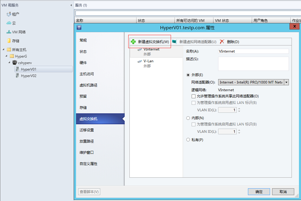
1.在Hyper-V主机上通过Hyper-V管理器新建虚拟交换机,或者也可以在SCVMM中新建
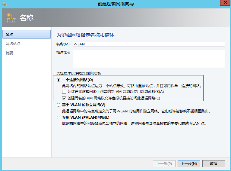
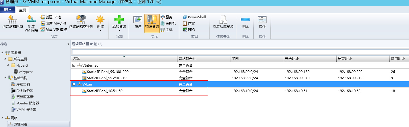
2.在SCVMM中先创建逻辑网络,再创建VM网络(实际上就是关联已经在Hyper-V主机上创建的虚拟交换机)
注:如果选中“创建同名VM网络”,则不需要再单独创建VM网络
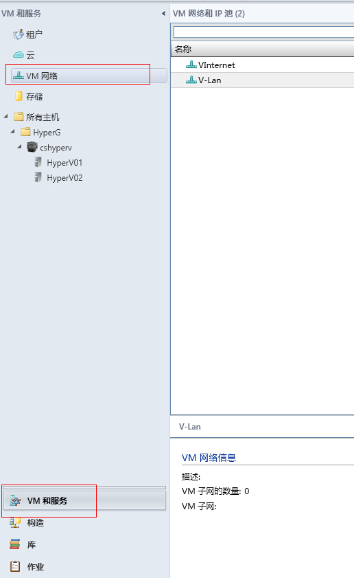
查看或删除新建的VM网络:VM网络和服务--VM网络
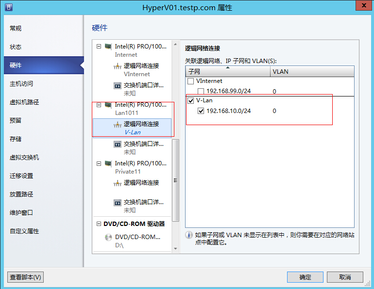
3.在SCVMM中的 Hyper-V主机 的属性--硬件中找到相应的网卡,然后关联逻辑网络,否则在将虚机分配到主机的时候,会提示找不到VM网络