


A method and apparatus enable Internet of Things (IoT) services based on a SMART IoT architecture by integrating connectivity, content, cognition, context, cloud, and collaboration. Joint optimization of a combination of any of connectivity, content, cognition, context, cloud, or collaboration may be utilized. Also in the method and apparatus, any of cloud computing, cognitive and collaborative networking, content-centric networking, or context-awareness may be jointly leveraged.
BACKGROUND
[0002] As the Internet evolves and as users come to demand and expect better Internet services, it may be important to shift away from the current focus of the Internet on data collection and towards more evolved techniques to improve user experience. Further, emerging technologies such as sensors, radio frequency identification (RFID) and near-field communications (NFC) make it possible to connect all physical things or objects together in an Internet of Things (IoT).
[0003] It is, therefore, desirable to have smart IoT services. It is also desirable for Machine-to-Machine (M2M) or IoT architectures to be content-centric, context-aware, cloud-based, collaborative and cognitive, so that smart IoT services may be achieved.
SUMMARY
[0004] A method and apparatus enable Internet of Things (IoT) services based on a SMART IoT architecture by integrating connectivity, content, cognition, context, cloud, and collaboration. Joint optimization of a combination of any of connectivity, content, cognition, context, cloud, or collaboration may be utilized. Also in the method and apparatus, any of cloud computing, cognitive and collaborative networking, content- centric networking, or context-awareness may be jointly leveraged.
[0005] A SMART IoT architecture may consist of system-level structure, service-level structure, informational elements, interfaces, and protocol stack. SMART may be a distributed IoT architecture where IoT services may be located at and requested from different entities within the network. SMART may be a flexible IoT architecture where an IoT entity, such as, for example, a server, gateway, or device, may use and host different combinations of IoT services depending on its context. IoT information has great variety. The SMART IoT architecture may use categorization of information in terms of any of entity, service, capability, application, content, context, policy, decision, or event informational elements. Additionally, the SMART IoT architecture may define mechanisms to formulate and manipulate each informational element.
[0006] The SMART IoT architecture may include a set of foundational cognition-centric C6 capabilities including Connectivity, Content, Context, Cloud, Collaboration, and Cognition. The SMART IoT architecture may include mechanisms for jointly leveraging the C6 capabilities and in turn enabling the SMART architecture to achieve high scalability, manageability, adaptability, reliability, and trustworthiness. Additionally, the foundational C6 capabilities may be leveraged to achieve more advanced C6-enabled IoT services. SMART IoT architecture mechanisms may leverage the foundational C6 capabilities as well as the more advanced C6-enabled services to improve technologies such as, for example, the European Telecommunications Standards Institute (ETSI) M2M service layer, one M2M service layer, Internet Engineering Task Force (IETF) IoT protocols, 3rd Generation Partnership Project (3GPP) networks, Institute of Electrical and Electronics Engineers (IEEE) protocols such as IEEE 802.15.8 for peer-aware communications, Content Delivery Network (CDN)-based IoT network architectures, and Cloud-based IoT network architectures.
DETAILED DESCRIPTION
[0039] FIG. 1A is a diagram of an example communications system 100 in which one or more disclosed embodiments may be implemented. The communications system 100 may be a multiple access system that provides content such as voice, data, video, messaging, broadcast, etc., to multiple wireless users. The communications system 100 may enable multiple wireless users to access such content through the sharing of system resources, including wireless bandwidth. For example, the communications system 100 may employ one or more channel access methods, such as code division multiple access (CDMA), time division multiple access (TDMA), frequency division multiple access (FDMA), orthogonal FDMA (OFDMA), single-carrier FDMA (SC-FDMA), and the like.

[0040] As shown in FIG. 1A, the communications system 100 may include wireless transmit/receive units (WTRUs) 102a, 102b, 102c, 102d, a radio access network (RAN) 104, a core network 106, a public switched telephone network (PSTN) 108, the Internet 110, and other networks 112, though it will be appreciated that the disclosed embodiments contemplate any number of WTRUs, base stations, networks, and/or network elements. Each of the WTRUs 102a, 102b, 102c, 102d may be any type of device configured to operate and/or communicate in a wireless environment. By way of example, the WTRUs 102a, 102b, 102c, 102d may be configured to transmit and/or receive wireless signals and may include a user equipment (UE), a mobile station, a fixed or mobile subscriber unit, a pager, a cellular telephone, a personal digital assistant (PDA), a smartphone, a laptop, a netbook, a personal computer, a wireless sensor, consumer electronics, and the like.
[0041] The communications system 100 may also include a base station 114a and a base station 114b. Each of the base stations 114a, 114b may be any type of device configured to wirelessly interface with at least one of the WTRUs 102a, 102b, 102c, 102d to facilitate access to one or more communication networks, such as the core network 106, the Internet 110, and/or the other networks 112. By way of example, the base stations 114a, 114b may be a base transceiver station (BTS), a Node-B, an eNode-B, a Home Node B, a Home eNode-B, a site controller, an access point (AP), a wireless router, and the like. While the base stations 114a, 114b are each depicted as a single element, it will be appreciated that the base stations 114a, 114b may include any number of interconnected base stations and/or network elements.
[0042] The base station 114a may be part of the RAN 104, which may also include other base stations and/or network elements (not shown), such as a base station controller (BSC), a radio network controller (RNC), relay nodes, etc. The base station 114a and/or the base station 114b may be configured to transmit and/or receive wireless signals within a particular geographic region, which may be referred to as a cell (not shown). The cell may further be divided into cell sectors. For example, the cell associated with the base station 114a may be divided into three sectors. Thus, in one embodiment, the base station 114a may include three transceivers, i.e., one for each sector of the cell. In another embodiment, the base station 114a may employ multiple-input multiple output (MIMO) technology and, therefore, may utilize multiple transceivers for each sector of the cell.
[0043] The base stations 114a, 114b may communicate with one or more of the WTRUs 102a, 102b, 102c, 102d over an air interface 116, which may be any suitable wireless communication link (e.g., radio frequency (RF), microwave, infrared (IR), ultraviolet (UV), visible light, etc.). The air interface 116 may be established using any suitable radio access technology (RAT).
[0044] More specifically, as noted above, the communications system 100 may be a multiple access system and may employ one or more channel access schemes, such as CDMA, TDMA, FDMA, OFDMA, SC-FDMA, and the like. For example, the base station 114a in the RAN 104 and the WTRUs 102a, 102b, 102c may implement a radio technology such as Universal Mobile Telecommunications System (UMTS) Terrestrial Radio Access (UTRA), which may establish the air interface 116 using wideband CDMA (WCDMA). WCDMA may include communication protocols such as High-Speed Packet Access (HSPA) and/or Evolved HSPA (HSPA+). HSPA may include High-Speed Downlink Packet Access (HSDPA) and/or High-Speed Uplink Packet Access (HSUPA).
[0045] In another embodiment, the base station 114a and the WTRUs 102a, 102b, 102c may implement a radio technology such as Evolved UMTS Terrestrial Radio Access (E-UTRA), which may establish the air interface 116 using Long Term Evolution (LTE) and/or LTE-Advanced (LTE-A).
[0046] In other embodiments, the base station 114a and the WTRUs 102a, 102b, 102c may implement radio technologies such as Institute of Electrical and Electronics Engineers (IEEE) 802.16 (i.e., Worldwide Interoperability for Microwave Access (WiMAX)), CDMA2000, CDMA2000 IX, CDMA2000 EV-DO, Interim Standard 2000 (IS-2000), Interim Standard 95 (IS-95), Interim Standard 856 (IS-856), Global System for Mobile communications (GSM), Enhanced Data rates for GSM Evolution (EDGE), GSM EDGE (GERAN), and the like.
[0047] The base station 114b in FIG. 1A may be a wireless router, Home Node B, Home eNode-B, or access point, for example, and may utilize any suitable RAT for facilitating wireless connectivity in a localized area, such as a place of business, a home, a vehicle, a campus, and the like. In one embodiment, the base station 114b and the WTRUs 102c, 102d may implement a radio technology such as IEEE 802.11 to establish a wireless local area network (WLAN). In another embodiment, the base station 114b and the WTRUs 102c, 102d may implement a radio technology such as IEEE 802.15 to establish a wireless personal area network (WPAN). In yet another embodiment, the base station 114b and the WTRUs 102c, 102d may utilize a cellular-based RAT (e.g., WCDMA, CDMA2000, GSM, LTE, LTE-A, etc.) to establish a picocell or femtocell. As shown in FIG. 1A, the base station 114b may have a direct connection to the Internet 110. Thus, the base station 114b may not be required to access the Internet 110 via the core network 106.
[0048] The RAN 104 may be in communication with the core network 106, which may be any type of network configured to provide voice, data, applications, and/or voice over internet protocol (VoIP) services to one or more of the WTRUs 102a, 102b, 102c, 102d. For example, the core network 106 may provide call control, billing services, mobile location-based services, pre-paid calling, Internet connectivity, video distribution, etc., and/or perform high-level security functions, such as user authentication. Although not shown in FIG. 1A, it will be appreciated that the RAN 104 and/or the core network 106 may be in direct or indirect communication with other RANs that employ the same RAT as the RAN 104 or a different RAT. For example, in addition to being connected to the RAN 104, which may be utilizing an E-UTRA radio technology, the core network 106 may also be in communication with another RAN (not shown) employing a GSM radio technology.
[0049] The core network 106 may also serve as a gateway for the WTRUs 102a, 102b, 102c, 102d to access the PSTN 108, the Internet 110, and/or other networks 112. The PSTN 108 may include circuit-switched telephone networks that provide plain old telephone service (POTS). The Internet 110 may include a global system of interconnected computer networks and devices that use common communication protocols, such as the transmission control protocol (TCP), user datagram protocol (UDP) and the internet protocol (IP) in the TCP/IP internet protocol suite. The other networks 112 may include wired or wireless communications networks owned and/or operated by other service providers. For example, the other networks 112 may include another core network connected to one or more RANs, which may employ the same RAT as the RAN 104 or a different RAT.
[0050] Some or all of the WTRUs 102a, 102b, 102c, 102d in the communications system 100 may include multi-mode capabilities, i.e., the WTRUs 102a, 102b, 102c, 102d may include multiple transceivers for communicating with different wireless networks over different wireless links. For example, the WTRU 102c shown in FIG. 1A may be configured to communicate with the base station 114a, which may employ a cellular-based radio technology, and with the base station 114b, which may employ an IEEE 802 radio technology.
[0051] FIG. IB is a system diagram of an example WTRU 102. As shown in FIG. IB, the WTRU 102 may include a processor 118, a transceiver 120, a transmit/receive element 122, a speaker/microphone 124, a keypad 126, a display/touchpad 128, non-removable memory 130, removable memory 132, a power source 134, a global positioning system (GPS) chipset 136, and other peripherals 138. It will be appreciated that the WTRU 102 may include any subcombination of the foregoing elements while remaining consistent with an embodiment.

[0052] The processor 118 may be a general purpose processor, a special purpose processor, a conventional processor, a digital signal processor (DSP), a plurality of microprocessors, one or more microprocessors in association with a DSP core, a controller, a microcontroller, Application Specific Integrated Circuits (ASICs), Field Programmable Gate Array (FPGAs) circuits, any other type of integrated circuit (IC), a state machine, and the like. The processor 118 may perform signal coding, data processing, power control, input/output processing, and/or any other functionality that enables the WTRU 102 to operate in a wireless environment. The processor 118 may be coupled to the transceiver 120, which may be coupled to the transmit/receive element 122. While FIG. IB depicts the processor 118 and the transceiver 120 as separate components, it will be appreciated that the processor 118 and the transceiver 120 may be integrated together in an electronic package or chip. [0053] The transmit/receive element 122 may be configured to transmit signals to, or receive signals from, a base station (e.g., the base station 114a) over the air interface 116. For example, in one embodiment, the transmit/receive element 122 may be an antenna configured to transmit and/or receive RF signals. In another embodiment, the transmit/receive element 122 may be an emitter/detector configured to transmit and/or receive IR, UV, or visible light signals, for example. In yet another embodiment, the transmit/receive element 122 may be configured to transmit and receive both RF and light signals. It will be appreciated that the transmit/receive element 122 may be configured to transmit and/or receive any combination of wireless signals.
[0054] In addition, although the transmit/receive element 122 is depicted in FIG. IB as a single element, the WTRU 102 may include any number of transmit/receive elements 122. More specifically, the WTRU 102 may employ MIMO technology. Thus, in one embodiment, the WTRU 102 may include two or more transmit/receive elements 122 (e.g., multiple antennas) for transmitting and receiving wireless signals over the air interface 116.
[0055] The transceiver 120 may be configured to modulate the signals that are to be transmitted by the transmit/receive element 122 and to demodulate the signals that are received by the transmit/receive element 122. As noted above, the WTRU 102 may have multi-mode capabilities. Thus, the transceiver 120 may include multiple transceivers for enabling the WTRU 102 to communicate via multiple RATs, such as UTRA and IEEE 802.11, for example.
[0056] The processor 118 of the WTRU 102 may be coupled to, and may receive user input data from, the speaker/microphone 124, the keypad 126, and/or the display/touchpad 128 (e.g., a liquid crystal display (LCD) display unit or organic light-emitting diode (OLED) display unit). The processor 118 may also output user data to the speaker/microphone 124, the keypad 126, and/or the display/touchpad 128. In addition, the processor 118 may access information from, and store data in, any type of suitable memory, such as the non-removable memory 130 and/or the removable memory 132. The non-removable memory 130 may include random-access memory (RAM), read-only memory (ROM), a hard disk, or any other type of memory storage device. The removable memory 132 may include a subscriber identity module (SIM) card, a memory stick, a secure digital (SD) memory card, and the like. In other embodiments, the processor 118 may access information from, and store data in, memory that is not physically located on the WTRU 102, such as on a server or a home computer (not shown).
[0057] The processor 118 may receive power from the power source 134, and may be configured to distribute and/or control the power to the other components in the WTRU 102. The power source 134 may be any suitable device for powering the WTRU 102. For example, the power source 134 may include one or more dry cell batteries (e.g., nickel-cadmium (NiCd), nickel-zinc (NiZn), nickel metal hydride (NiMH), lithium-ion (Li-ion), etc.), solar cells, fuel cells, and the like.
[0058] The processor 118 may also be coupled to the GPS chipset 136, which may be configured to provide location information (e.g., longitude and latitude) regarding the current location of the WTRU 102. In addition to, or in lieu of, the information from the GPS chipset 136, the WTRU 102 may receive location information over the air interface 116 from a base station (e.g., base stations 114a, 114b) and/or determine its location based on the timing of the signals being received from two or more nearby base stations. It will be appreciated that the WTRU 102 may acquire location information by way of any suitable location- determination method while remaining consistent with an embodiment.
[0059] The processor 118 may further be coupled to other peripherals 138, which may include one or more software and/or hardware modules that provide additional features, functionality and/or wired or wireless connectivity. For example, the peripherals 138 may include an accelerometer, an e-compass, a satellite transceiver, a digital camera (for photographs or video), a universal serial bus (USB) port, a vibration device, a television transceiver, a hands free headset, a Bluetooth® module, a frequency modulated (FM) radio unit, a digital music player, a media player, a video game player module, an Internet browser, and the like.
[0060] FIG. 1C is a system diagram of the RAN 104 and the core network 106 according to an embodiment. As noted above, the RAN 104 may employ an E-UTRA radio technology to communicate with the WTRUs 102a, 102b, 102c over the air interface 116. The RAN 104 may also be in communication with the core network 106.

[0061] The RAN 104 may include eNode-Bs 140a, 140b, 140c, though it will be appreciated that the RAN 104 may include any number of eNode-Bs while remaining consistent with an embodiment. The eNode-Bs 140a, 140b, 140c may each include one or more transceivers for communicating with the WTRUs 102a, 102b, 102c over the air interface 116. In one embodiment, the eNode-Bs 140a, 140b, 140c may implement MIMO technology. Thus, the eNode-B 140a, for example, may use multiple antennas to transmit wireless signals to, and receive wireless signals from, the WTRU 102a.
[0062] Each of the eNode-Bs 140a, 140b, 140c may be associated with a particular cell (not shown) and may be configured to handle radio resource management decisions, handover decisions, scheduling of users in the uplink and/or downlink, and the like. As shown in FIG. 1C, the eNode-Bs 140a, 140b, 140c may communicate with one another over an X2 interface.
[0063] The core network 106 shown in FIG. 1C may include a mobility management gateway (MME) 142, a serving gateway 144, and a packet data network (PDN) gateway 146. While each of the foregoing elements are depicted as part of the core network 106, it will be appreciated that any one of these elements may be owned and/or operated by an entity other than the core network operator.
[0064] The MME 142 may be connected to each of the eNode-Bs 140a, 140b,140c in the RAN 104 via an Si interface and may serve as a control node. For example, the MME 142 may be responsible for authenticating users of the WTRUs 102a, 102b, 102c, bearer activation/deactivation, selecting a particular serving gateway during an initial attach of the WTRUs 102a, 102b, 102c, and the like. The MME 142 may also provide a control plane function for switching between the RAN 104 and other RANs (not shown) that employ other radio technologies, such as GSM or WCDMA.
[0065] The serving gateway 144 may be connected to each of the eNode-Bs 140a, 140b, 140c in the RAN 104 via the Si interface. The serving gateway 144 may generally route and forward user data packets to/from the WTRUs 102a, 102b, 102c. The serving gateway 144 may also perform other functions, such as anchoring user planes during inter-eNode-B handovers, triggering paging when downlink data is available for the WTRUs 102a, 102b, 102c, managing and storing contexts of the WTRUs 102a, 102b, 102c, and the like.
[0066] The serving gateway 144 may also be connected to the PDN gateway 146, which may provide the WTRUs 102a, 102b, 102c with access to packet-switched networks, such as the Internet 110, to facilitate communications between the WTRUs 102a, 102b, 102c and IP-enabled devices. An access router (AR) 150 of a wireless local area network (WLAN) 155 may be in communication with the Internet 110. The AR 150 may facilitate communications between APs 160a, 160b, and 160c. The APs 160a, 160b, and 160c may be in communication with STAs 170a, 170b, and 170c. A STA 170 may be a wireless device such as WTRU 102.
[0067] The core network 106 may facilitate communications with other networks. For example, the core network 106 may provide the WTRUs 102a, 102b, 102c with access to circuit-switched networks, such as the PSTN 108, to facilitate communications between the WTRUs 102a, 102b, 102c and traditional land-line communications devices. For example, the core network 106 may include, or may communicate with, an IP gateway (e.g., an IP multimedia subsystem (IMS) server) that serves as an interface between the core network 106 and the PSTN 108. In addition, the core network 106 may provide the WTRUs 102a, 102b, 102c with access to the other networks 112, which may include other wired or wireless networks that are owned and/or operated by other service providers.
[0068] In some embodiments, the WTRU 102 may be a device that generates data such as a water meter, event detector, pressure sensor, temperature sensor, video camera, etc.
[0069] A next era of Internet will be sensor-based computing. Emerging technologies, such as sensors, radio frequency identification (RFID) and near-field communications (NFC), make it possible to connect physical things or objects together into an Internet of Things (IoT) as a big picture for future Internet. Moving beyond simply connecting things to the Internet, services provided on each object may be leveraged to create a Web of Things (WoT) or Internet of Services (IoS). In addition, the interaction between physical objects and Internet may be bi-directional. Physical objects may be managed and controlled in a real-time fashion. Broad goals of IoT may include: things/objects may be seamlessly connected to Internet; physical environment may be learned and reversely adapted via connected things/objects; things/objects provide services, which may be discovered and shared; and interactions between physical environment and Internet (or computational systems) are handled through the services provided by things/objects.
[0070] IoT system may have highly diverse characteristics with massive heterogeneity. For example, IoT may receive input to and output/feedback from the physical environment. Physical objects may move and interact with their surroundings such as, for example, other objects. Such interactions may be spontaneous and events may be generated automatically. The number of objects may be large and the objects may have different characteristics, for example, in terms of size, resource, mobility, connectivity, automation, deployment, or lifetime, to name a few.
[0071] The communication networks for connecting objects to Internet may be heterogeneous as well in different dimensions such as, for example, communication technologies, network size, network topology, and network coverage. A Wireless Sensor Network (WSN) may be, for example, one-hop or multi-hop, and may have a linear, star, tree, mesh, or other topology. With regard to network coverage, physical objects may be sparsely or densely deployed and may generate minimal to high redundancy.
[0072] Regarding traffic from and to the physical environment, physical objects may generate data streams, which may be, for example, event-driven, query-driven, or periodical. There may be uncertainty in the readings or raw sensory data from physical objects. Some objects, such as for example distributed cameras, may generate high-speed data stream, while other objects may generate low and extremely low data rate streams. Different traffic modes may exist, including for example, anycast, multicast, broadcast, or converge-east traffic modes.
[0073] Regarding services, raw sensory data or readings may be interpreted in the context of physical environments (i.e. situation/context-awareness) in order to provide semantics services. Some services may be time sensitive. For example, the actions for controlling physical environments may be performed over objects in real-time fashion. A physical object may provide multiple types of services or multiple objects may together provide the same service.
[0074] To satisfy various requirements of diverse IoT applications, a smart architecture solution may be used for the future IoT, providing several properties and capabilities. A SMART C6-based IoT architecture may include: foundational "C6" capabilities including Connectivity, Content, Context, Cloud, Collaboration, and Cognition to improve IoT services; a C6-enabled IoT architecture including system level structure, service level structure, interfaces, protocol stack, informational elements; and implementations of the C6-enabled IoT architecture for technologies including, but not limited to, for example, the ETSI M2M service layer, IETF protocols, 3rd Generation Partnership Protocol (3GPP) networks, Content Delivery Network (CDN)-based network architectures and Cloud-based network architectures.
[0075] Future IoT architecture may be scalable with the ever-increasing number and types of things, devices, data and services connecting to the Internet. It may meet requirements of different IoT applications in a scalable way. The challenges lie in the multiple dimensions and complexities in IoT systems. Future IoT architecture may support not only physical observation, but also semantic data and services. Data annotation and data analytics may play an important role to link data together and to mine relations, perceptions, and even high-level context. Semantics may be applied to other IoT areas such as service management including discovery and caching.
[0076] Future IoT architecture may support efficient management of IoT things, devices, data and services. Examples of service management include, for example, service advertisement, service discovery, service delivery, and service diagnosis. In addition, IoT things, devices, data and service may be coupled and dependent of each other. As a result, a unified approach to manage them in an integrated fashion may be more appropriate. In addition, providing an autonomous self-organization of IoT things, device, data and services may be useful so that different IoT systems may work together.
[0077] Future IoT architecture may be adaptive. Through adaptation, future IoT architecture may support intelligently adjusting protocols and services to the needs of IoT entities. It may, for example, be highly responsive to critical changes from physical environment and networking dynamics. Software-defined adaptation in different protocol layers may be leveraged, such as, for example, software- defined communication protocol adaptation, or software-defined service adaptation.
[0078] Future IoT architecture may be reliable and robust to different IoT system limitations such as, for example, resource-constrained devices and unreliable wireless radio links. Reliability may be guaranteed separately or jointly in different protocol layers. In addition, the architecture may provide sustainability, for example, through energy- efficient communications and networking. Future IoT architecture may also support secure IoT services and may guarantee privacy, especially for privacy- sensitive IoT services and applications such as, for example, smart health and smart grid. Data aggregation may be leveraged to hide resource originators and provide certain levels privacy.
[0079] Some existing M2M/IoT architectures, such as, for example, ETSI M2M, may focus on communications and data collection (i.e. how information is transmitted from one machine to another) with limited or no support for some of the above mentioned properties. For example, the ETSI M2M service architecture has an M2M server as a centralized point and therefore lacks scalability. In another example, ETSI M2M has just started to work the topic of semantics but does not have a solid solution yet. In addition, ETSI M2M has not fully addressed adaptation, reliability, sustainability, and privacy. Existing M2M/IoT architectures have the following additional drawbacks.
[0080] Certain existing M2M/IoT architectures may lack standardized horizontal IoT architecture, protocols and Application Programming Interfaces (APIs) defined for collecting, storing, addressing, mining/querying, and routing of content on objects or in the network. Certain Internet protocols may not have been designed with connectivity to IoT objects in mind. IoT connections may differ from traditional network connections in that they are more lossy, asymmetric, and intermittent.
[0081] Certain existing M2M/IoT architectures may lack a standardized horizontal IoT content model defining syntax and structure of IoT content (i.e. semantic data model). Proposed data models are typically fragmented and target specific vertical markets such as, for example, healthcare or building automation.
[0082] Certain existing M2M/IoT architectures may lack a standardized horizontal IoT model defining syntax and structure of IoT context or ontology, and may also lack a standardized horizontal IoT model defining syntax and structure of IoT cognition.
[0083] Certain existing M2M/IoT architectures may lack protocols, interfaces or APIs specifically targeting collaboration between IoT objects and other network entities. Lack of universally adopted protocols and APIs to allow IoT objects to collaborate and use network based services (e.g. cloud based services or peer-to-peer (P2P) services) may be a barrier.
[0084] Certain IoT objects may be unable to host smart IoT services locally due to, for example, limited resources, but may benefit from using smart IoT services hosted in the network. Certain existing M2M/IoT architectures may lack universally adopted protocols and APIs to allow IoT objects to collaborate and use network based services (e.g. cloud based services or P2P services).
[0085] Certain existing M2M/IoT architectures may lack mechanisms to provide cloud-based services for IoT objects and in turn allow IoT objects to use those cloud-based services. Many IoT objects may have limited discovery, communication, security, and power capabilities that may restrict these objects from discovering and interacting with cloud-based services. Hence, for IoT cloud based deployments, a major challenge may be finding efficient ways to enable IoT objects to use cloud based services.
[0086] Accordingly, it is desirable to design a future smart IoT architecture that may support scalability, semantics, manageability, adaptation, reliability and sustainability, and trustworthiness while overcoming drawbacks in existing M2M/IoT architectures.
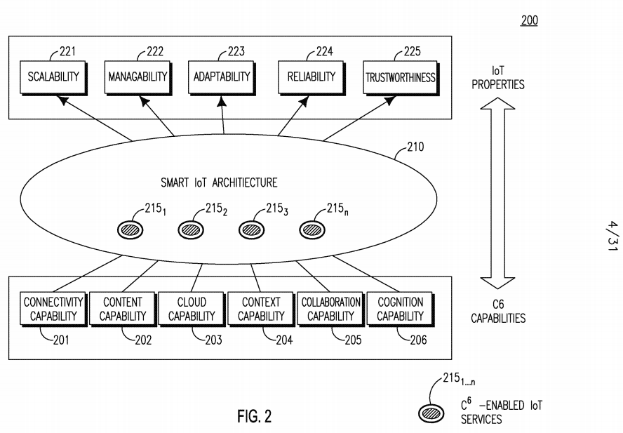
[0087] A SMART C6-enabled IoT architecture is designed with a set of foundational C6 capabilities to address the above-mentioned problems and challenges arising in the design of IoT networks. Figure 2 is a high-level diagram 200 showing the C6 capabilities meeting future IoT requirements using C6- enabled IoT services. The SMART IoT architecture 210 uses C6-enabled IoT Services 215i...n, which provide the foundational "C6" capabilities including Connectivity 201, Content 202, Cloud 203, Context 204, Collaboration 205, and Cognition 206 to improve IoT services 215i...n. As a result, the following properties, among others, may be achieved: scalability 221, manageability 222, adaptability 223, reliability 224, and trustworthiness 225. [0088] Regarding the connectivity capability 201, the C6-enabled architecture may improve connectivity performance and may provide connectivity as a service to make future IoT systems more reliable and sustainable. Regarding the content capability 202, the C6-enabled architecture may support efficient collection of massive amounts of diverse data produced by objects and content-based addressing and routing within the network. Advanced content techniques such as content-aware discovery, caching, and delivery may be leveraged to improve service performance. Content- centric design may help to improve IoT semantics and scalability.
[0089] Regarding cloud capability 203, the C6-enabled architecture, may provide mechanisms to support the creation, presence, discovery and use of cloud- based services. A cloud-based solution may facilitate a more scalable, manageable, reliable, sustainable and trustworthy IoT. Regarding context capability 204, the C6-enabled architecture may be context-aware, which supports awareness of physical environment or surrounding properties such as, for example, location, time, residual resources, wireless link quality, and even semantic annotation on content. In turn, context-awareness may leverage such context information to improve the whole system and may improve IoT scalability, adaptability and semantics.
[0090] Regarding collaboration capability 205, the C6-enabled architecture is a collaborative system, which includes mechanisms to facilitate collaboration amongst objects, services, applications and the network to improve IoT reliability and sustainability and even trustworthiness. Regarding cognition capability 206, the C6-enabled architecture may be cognitive, and may support mining and learning knowledge and context from objects, networks, content and cloud and making autonomous system adjustments to enable semantic and adaptive IoT.
[0091] Using these C6 capabilities as a foundation, the SMART IoT architecture may also support a set of more advanced C6-enabled IoT services 215i...n. These advanced C6-enabled IoT services 215i...n may leverage underlying functionality of one or more of the foundational C6 capabilities, as shown in Figure 2.
[0092] A SMART IoT architecture may consist of system-level structure, service-level structure, informational elements, interfaces, and protocol stack. SMART may be a distributed IoT architecture where IoT services may be located at and requested from different entities within the network. SMART may be a flexible IoT architecture where an IoT entity, such as, for example, a server, gateway, or device, may use and host different combinations of IoT services depending on its context. IoT information has great variety. As a result, it may be challenging to categorize the information elements in IoT. The SMART IoT architecture may use categorization of information in terms of any of entity, service, application, content, context, policy, decision, or event informational elements. Additionally, the SMART IoT architecture may define mechanisms to formulate and manipulate each informational element.
[0093] The SMART IoT architecture may include a set of foundational cognition-centric C6 capabilities including Connectivity, Content, Context, Cloud, Collaboration, and Cognition. The SMART IoT architecture may include mechanisms for jointly leveraging the C6 capabilities and in turn enabling the SMART architecture to achieve high scalability, manageability, adaptability, reliability, and trustworthiness. Additionally, the foundational C6 capabilities may be leveraged to achieve more advanced C6-enabled IoT services. SMART IoT architecture mechanisms may leverage the foundational C6 capabilities as well as the more advanced C6-enabled services to improve technologies such as, for example, the ETSI M2M service layer, IETF IoT protocols, 3GPP networks, CDN-based IoT network architectures, and Cloud-based IoT network architectures.
[0094] Figure 3 shows a C6 cube-based reference model 300 for the SMART IoT architecture. Via this model, each foundational C6 capability (Connectivity 301, Content 302, Cloud 303, Context 304, Collaboration 305, and Cognition 306) may interact with its five other counter-part C6 capabilities and together to provide functionality that none of the C6 capabilities alone may provide. The premise of this model in the context of existing M2M architectures may be thought of as the integration of connectivity 301 and content 302 with context 304, collaboration 305, cloud 303, and cognition 306. This reference model 300 illustrates the goal to design a C6-enabled IoT architecture with advanced capabilities. Using these capabilities as a foundation, higher level and more advanced services may in turn be enabled. These services and underlying capabilities may be used by future M2M/IoT systems that in turn may enable a global network of interconnected smart objects.
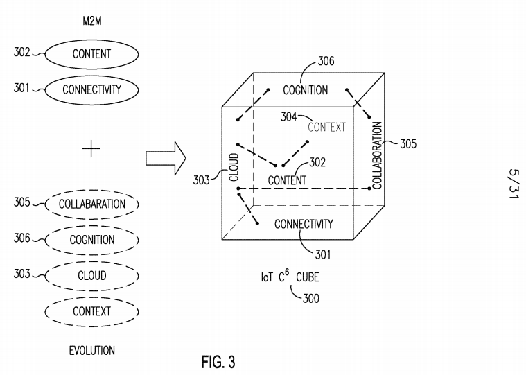
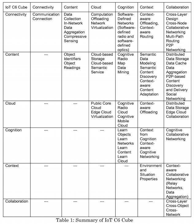
[0095] M2M solutions may be focused on communications, specifically how information is transmitted from one machine to another. Evolution will effectively integrate "connectivity" and "content" with "context", "collaboration", "cloud", and "cognition". A future IoT may be a global network of interconnected objects that may enable object identification and discovery and semantic data processing via C6. Connectivity 301 may provide connection for mobile and constrained objections. Content302 may include massive data produced from things. Cloud 303 may provide cloud service and cloud storage content. Context 304 may provide context-aware design to improve performance. Collaboration 305 may provide cooperative communications, inter-things and service sharing. Cognition 306 may mine knowledge from massive data and provide autonomous system adjustment for improvements. The future IoT, based on the C6 Cube 300, may enable the integration and interaction between connectivity 301, content 302, cognition 306, context 304, cloud 303, and collaboration 305, so as to jointly leverage cloud computing, cognitive and collaborative networking, content-centric networking, and context-awareness to design future IoT architecture and techniques in a systematic approach. Each of the C6 cube properties are discussed in further detail below, and are summarized in Table 1.
[0096] Regarding connectivity, physical objects may need communication connections to and from the Internet. However, there may be no guarantee to provide permanent connectivity for physical objects, especially for mobile objects in Intermittently Connected Networks (ICN) or Delay-Tolerant Networks (DTN). Connectivity may help provide reliable, low-latency, and energy- efficient communication paths. Connectivity may be end-to-end or hop-by-hop or in a hybrid fashion in different layers. Split transmission control protocol (TCP) may break end-to-end principle in non-split TCP, but may help reduce Round-Trip Time (RTT) and isolate problematic links.
[0097] Different technologies may be applied to achieve connectivity. For example, multi-path routing may help improve connectivity reliability. In another example, cognitive radio may be used to create additional connectivity and may improve system bandwidth and reliability. In another example, collaborative networking may enhance reliability. In another example, communication offloading may improve energy-efficiency and reliability. Any techniques may be jointly designed with context-awareness. For example, context-aware communication offloading may optimize offloading efficiency even more based on objects' context such as location, time, and residual energy.
[0098] Content in future IoT may include object identifiers and massive real-time raw data generated by physical objects. Raw data may have uncertainty such as False Positive Reading (FPR) and False Negative Reading (FNR). Raw data may also need to be annotated with useful semantics/context and mined to obtain useful knowledge. A challenge lies in collecting, storing, mining, and querying massive data streams in an efficient manner in terms of, for example, consumed energy, consumed time, consumed storage space, and consumed bandwidth, among other things.
[0099] Well-defined identifier schemes may enable efficient identifier lookup and storage. In- network data aggregation may help to save connectivity bandwidth. Cloud-based storage may improve reliability and data query response speed. Semantic data modeling may enable meaningful query and semantic web service. Collaborative data cache and aggregation and distributed data storage may improve content management efficiency. [0100] Cloud storage may provide more powerful storage and computation capabilities than objects. Massive content generated by physical objects may be stored and processed in the cloud. For example, sensitive content may be stored in a private cloud, while frequently-changed and less-accessed content may be stored in edge clouds. Intra-cloud and inter-cloud collaboration may occur. Computation offloading may be possible by pushing computation-intensive tasks from objects to the cloud. Context-aware offloading may optimize overall offloading benefits. Cloud storage may be utilized to store and analyze radio map information to enable cognitive radio mobile cloud. Virtualization may be a key technology for cloud computing and storage. Security and privacy for cloud technologies may provide reliable cloud services.
[0101] Collaboration may occur, for example, among protocol layers, among objects, or among networks. In other examples, collaboration may occur between objects and cloud, between network edge and the cloud, or between edge clouds. Cross-layer design may be considered intra-object collaboration, while Peer-to- Peer (P2P), content cache and data aggregation may be considered cross-object (or cross-node) collaboration. Collaboration may be one-hop such as, for example, collaborative MAC protocols or multi-hop such as multi-hop relay networks. Collaboration may be used to improve cognitive radio, for example, the sensing accuracy. In addition, context- aware design may improve collaboration efficiency furthermore by leveraging object diversity, for example, for constrained devices.
[0102] Context may refer to physical environment or surrounding properties such as, for example, location, time, residual resources, wireless link quality, or semantic annotation on content, among others. Physical object, network and cloud may each have a different context. Context-aware design may refer to leveraging timely context information to optimize communication and networking protocols such as, for example, context-aware offloading, context- aware collaborative networking, context-aware content adaptation, semantic object and content discovery, and semantic IoT services, among others. A challenge may be how to model context and how to exploit context to optimize IoT systems to provide better services.
[0103] Cognition may refer to mining and learning knowledge and timely context from, for example, objects, networks, content and cloud. As a result, autonomous system adjustments may be made based on learned knowledge and context to enable, for example, Software-Define Radio (SDR), Software-Defined Optics (SDO), and Software-Defined Networks (SDN), among others. Collaboration and context-aware design may improve data mining and cognitive networking even more.
[0104] Figure 4 illustrates a system level view of a SMART C6 IoT architecture 400. The C6-enabled IoT architecture 400 is based on the C6 reference model illustrated in Figure 3. The C6 IoT architecture 400 may be segmented into the following domains: the IoT Services Domain 410, and the IoT Applications domain 412. The IoT Services Domain 410 may consists of various IoT entities hosting C6-enabled IoT services 406. These services 406 may provide IoT applications and IoT entities with scalability, semantics, manageability, adaptation, reliability, sustainability, and trustworthiness functionality for the IoT. These C6-enabled services 406 may leverage the underlying foundational C6 capabilities. The C6-enabled services 406 may be implemented within the protocol stack of a hosting entity or may be implemented as a capability hosted locally on the same IoT entity or on another accessible IoT entity in the network. The IoT Applications Domain 412 may consist of applications and/or users 415 that interface to the IoT Services Domain 410. These applications/users 415 may use the C6-enabled IoT services 406 hosted within the IoT Services Domain 410. The C6 IoT architecture domains 410 and 412 may be further segmented to include any of the following partitions: things (physical or virtual) 418, access networks 420, core networks 422, clouds 424, and the applications/users 415.
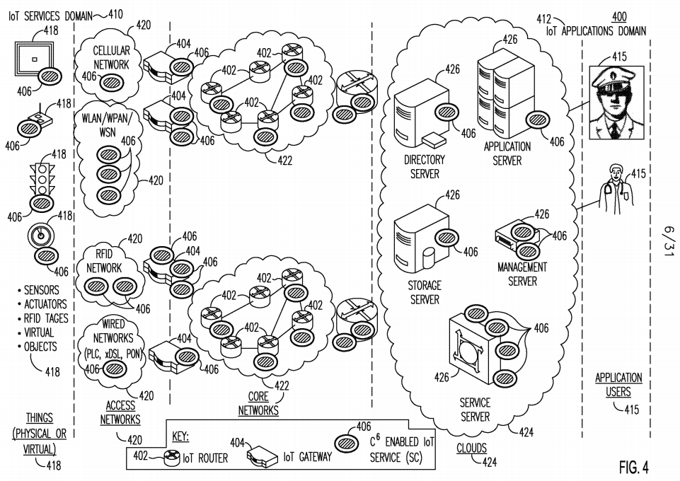
[0105] Things (or objects) 418 may include physical and virtual objects. Physical things 418 may have a communication module to provide connectivity to the Internet via access networks 420. Examples of physical things include, for example, sensors, actuators, and RFID tags. For example, a traffic light is a physical object 418 that is an actuator, and a thermometer is a physical object 418 that is a sensor. A physical thing 418 may be virtualized into a virtual thing 418. Virtual things 418 such as, for example, the environment, may be observed and controlled by sensors and actuators. By such means, virtual things 418 may be connected to the Internet. Each thing 418 may or may not host one or more C6-enabled IoT services 406, as shown in Figure 4, and/or may use C6-enabled IoT services 406 hosted on other entities in the network. C6-enabled IoT services 406 may be incorporated into an object's 418 protocol stack.
[0106] Access networks 420 may connect physical things 418 to the Internet. Some examples of access networks 420 include cellular networks, wireless local area networks (WLANs), wireless personal area networks (WPANs), wireless sensor networks (WSNs), RFID networks, and wired networks such as, for example, power line communications (PLC), Ethernet, digital subscriber line (xDSL), and passive optical networks (PONs), among others. None, or one or more C6-enabled IoT services 406 may reside in an access network 420 such as, for example, in eNB, WiFi APs, or WPAN coordinators. C6-enabled IoT services 406 may also be incorporated into access network 420 protocol stacks.
[0107] An access network 420 may have one or more IoT gateways 404 acting as bridges to a core network 422. A core network 422 may be, for example, the public Internet or may be a private enterprise or operator owned network that may or may not interface to the public Internet. IoT routers 402 may be distributed in core networks 422. IoT routers 402 and IoT gateways 404 may each host zero, one or more C6-enabled IoT services 406. C6-enabled IoT services 406 may be incorporated into the protocol stacks of core network elements such as, for example, the gateways 404 and/or routers 402.
[0108] A cloud 424 may be a shared pool of configurable computing resources 426 including, for example, networks, servers, storage, applications, and services, among others. Examples of servers include directory servers, application servers, storage servers, management servers and service servers. These resources 426 may provide C6-enabled IoT services 406. The applications/users 415 may connect and use C6-enabled IoT services 406 that are hosted on cloud resources 426 (e.g. network servers) and/or on objects/things 418.
[0109] An IoT entity may take the form of, for example, an IoT Router 402, IoT Gateway 404, IoT Object 418, or a computing resource 426 such as, for example an IoT Server. Each IoT Entity may host none, or one or more advanced C6- Enabled IoT services 406. The C6 capabilities (as illustrated in Figure 3) may be leveraged as a foundation for more advanced higher layer services. In addition, a C6 capability may be implemented as a service itself. Advanced C6- enabled IoT services 406 may leverage the foundational C6 capabilities. These advanced C6-enabled IoT services 406 may be hosted on C6-enabled IoT Entities. [0110] A C6-enabled IoT service 406 may talk to another C6-enabled IoT service 406 directly or indirectly. Similarly, a C6- Enabled IoT Entity may talk to another C6-Enabled IoT Entity directly or indirectly. C6-enabled IoT services 406 and/or C6-Enabled IoT Entities may flexibly form a distributed, centralized, or hybrid architecture. A C6-Enabled IoT Entity may act as a proxy to manage a set of other C6-Enabled IoT Entities. Different C6-Enabled IoT Entities may have different combinations of C6-enabled IoT services 406. Multiple instances of the same type of C6-enabled IoT service 406 may be hosted on either the same or different C6-Enabled IoT Entities.
[0111] As described above, within each C6 IoT architecture partition, individual C6- Enabled IoT Entities may be defined. An IoT Entity may take the form of an IoT Router, IoT Gateway, IoT Object, or an IoT Server. Each IoT Entity may contain one or more C6-Enabled IoT services. The behavior of a C6- Enabled IoT Entity or C6-Enabled IoT may be dynamically updated, for example, by other IoT Entities, Services or Applications. This may allow for scalability, manageability, and adaptation of future IoT and may enable software-defined IoT, for example, where IoT Entities may form a centralized, distributed, or hybrid logical topology.
[0112] In an example, IoT servers in the cloud may act as a centralized controller to manage other IoT entities such as IoT routers, IoT gateways, and IoT objects. As another example, Figure 5 shows an example of a network 500 of distributed P2P connections of IoT entities hosting services. The IoT entities 502I...N may be connected with each other in a distributed P2P fashion. In this example, the IoT entities 502I...N are arranged in a distributed hash table (DHT) ring, such that certain entities (e.g. entities 5022 and 502N) may host one or more C6-enabled IoT services.

[0113] In an example of a hybrid approach, IoT servers may formulate a distributed P2P system, which together act as a centralized cloud to manage other IoT entities. For example, the other IoT entities may be logically organized into a distributed P2P system. Overall, a hybrid and/or hierarchical structure may be established, where some IoT entities on the hierarchical structure may act as a proxy for other IoT entities.
[0114] Each IoT Entity may host one or more C6-Enabled IoT services. Figure 6 shows a high-level diagram of a C6-enabled IoT service 600 interacting with the foundational C6 capabilities, including Connectivity 601, Context 602, Content 603, Collaboration 604, Cloud 605, and Cognition 606. The function of a C6-enabled IoT service 600 may be to support a particular type of IoT-related functionality 610 such as, for example, IoT service discovery or IoT event management, among others. Each C6-enabled IoT service 600 may leverage one or more foundational C6 capabilities coupled with functionality 610 specific to that C6-enabled IoT service 600.

[0115] A C6-enabled IoT service may talk to other C6-enabled IoT services directly or indirectly and may formulate a centralized, distributed, or hybrid logical topology. In an example, some C6-enabled IoT services may be hosted in the cloud (e.g. IoT server) and may serve other C6-enabled IoT services not in the cloud using a client-server model. In another example, all C6-enabled IoT services may be connected with each other using P2P such that a C6-enabled IoT service may be discovered and requested by other C6-enabled IoT services. Similar to IoT Entities, C6-enabled IoT services may form hybrid and hierarchical structures as well.
[0116] The foundational C6 capabilities may be hosted inside an individual C6-enabled IoT service, or a C6-enabled IoT service may access foundational C6 capabilities hosted on the same local IoT Entity or on another IoT Entity. Examples of different relationship between C6 IoT Entities, C6-enabled IoT Services, and Foundational C6 Capabilities are illustrated in Figures 7, 8 and 9. Figure 7 shows an example of sharing foundational C6 capabilities 702 embedded in C6-enabled IoT Services 706i...4 within a C6-enabled IoT entity 700. C6- enabled service 706i, 7062, and 7Ο63 are equipped with foundational C6 capabilities 702 and share them with C6-enabled service 7064. Each of the services 706i...4 has C6-enabled IoT service specific functionality 704. For example, if a service 706i is device management, functionalities specific to a device management service may include management data model and management command execution.

[0117] Figure 8 shows an example of separate foundational C6 capabilities 802 hosted on a common C6 IoT Entity 800 and shared by multiple C6-enabled IoT services 8O61...3. Each C6-enabled IoT services 8O61...3 may have its own C6- e3nabled IoT service specific functionality 804. Figure 9 shows an example of separate foundational C6 capabilities 906 hosted on a common C6 IoT Entity 901 and shared by another C6 IoT Entity 902. Each IoT Entity 901 and 902 has C6- enabled IoT services 908i...3 and 9IO1...3, respectfully, that are equipped with C6- enabled IoT service specific functionality 904.


[0118] Figure 10 shows a high-level diagram 1000 of an example the interactions and dependencies between the foundational C6 capabilities 1001- 1006. Possible dependencies are shown with arrows between each of the capabilities, including Connectivity 1001, Content 1002, Cloud 1003, Context 1004, Collaboration 1005, and Cognition 1006. Each capability 1001-1006 has an associated policy IOIO1...6, respectively, that defines its functionality. However, not all the dependencies are required, and, for example, any of the individual capabilities may be standalone in nature for certain deployments. Figure 10 illustrates an example scenario where the C6 capabilities may be cognition 1006 centric. In other words, in this example, the Cognition capability 1006 may play a master-like role to coordinate the other capabilities. The Cognition capability 1006 may maintain a main policy database ΙΟΙΟβ. Other C6 capabilities 1001- 1005 may support a local policy database IOIO1...5, respectively, as well. The Cognition capability 1006 may depend on non-opaque content, context, policies, and questions from any of the other capabilities 1001-1005 and may output decisions as well as policies to any of the other capabilities 1001-1005. The Cognition capability 1006 may actively issue decisions and new policies to any of the other C6 capabilities 1001-1005, or any of the other C6 capabilities 1001-1005 may request an action to be determined by the Cognition capability 1006. Other C6 capabilities 1001-1005 may not make final decisions, but they may perform certain preliminary analysis. The other C6 capabilities 1001-1005 may update their local policy database IOIO1...5, respectively. The interaction between the other C6 capabilities 1001-1005 may be direct or indirect via the Cognition capability 1006.

[0119] Figure 11 shows a service level view of the SMART C6 IoT architecture 1100. The service level view 1100 may be partitioned into a Data Plane 1102 and a Control and Management Plane 1104. Each plane exists on the IoT infrastructure 1130, and may be further partitioned into several layers, for example: IoT Communication Layer 1106, IoT Collection Layer 1108, IoT Interpretation Layer 1110, IoT Abstraction Layer 1112, IoT Reasoning Layer 1114, and IoT Application Layer 1116. These layers may map to protocol layers discussed further below. In each plane and in each layer, there may be one or more advanced C6-Enabled IoT services 1120x. Each C6-enabled service 1120x may provide a particular type of functionality and leverage any of the foundational C6 capabilities 1125. A C6-enabled IoT service 1120 may span across any number of layers and may also communicate and collaborate with other services 1120.
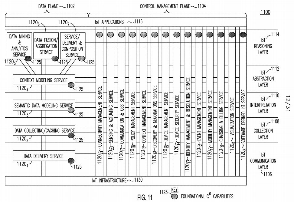
[0120] The following C6-enabled IoT services 1120x may exist in the data plane 1102. The Data Delivery Service 1120i may enable intelligent delivery of IoT data. The Data Collecting/Caching Service II2O2 may enable intelligent storage and caching of IoT data. The Semantic Data Modeling Service II2O3 may enable intelligent interpretation of IoT data. The Context Modeling Service II2O4 may enable embedding of context information within IoT data. The Data Mining and Analytics Service II2O5 may enable extracting information from IoT data. The Data Fusion/Aggregation Service 1120β may fuse and aggregate IoT data. The Data Plane Security Service (not shown) may enable securing IoT data. The Service Delivery & Composition Service II2O7 may enable delivery of an IoT Service 1120x from one IoT Entity to another and composition of higher level services by grouping delivered services with one another. Aspects of any of the above described data plane 1102 services 1120x may be categorized as control plan 1104 oriented.
[0121] The mechanisms may include C6-based delivery latency reduction by shortening delivery path such as using context-aware and collaborative storage/cache, choosing best (i.e. physically close) service providers, and/or adaptive service/content routing. Additionally, service the mechanisms may include negotiation and adaptation before service completion such as adjusting service providers, adjusting service QoS requirement, or adjusting content format, among other things, such that context information may be taken into consideration.
[0122] The following C6-enabled IoT services 1120x may exist in the control and management plane 1104. The Software Defined IoT Service 1120s may enable software programmability of C6-enabled IoT services. The Virtualization Service 1120g may enable virtualization of IoT Entities, services and/or content. The Charging/Billing Service 1120io may enable charging and billing for use of IoT services. The Mobility Management Service 1120n may enable managing mobile IoT data, entities and services. The Event Management Service 1120i2 may enable generating and servicing of IoT related events. The Identity Management and Resolution Service 1120i3 may enable managing identification of IoT data, services, entities, and naming resolution (e.g. through collaboration). The Device Security Service 1120i4 may enable security of IoT Entity data and services, and may enable integration and virtualization of existing security protocols and services for an IoT Entity. The Device Management C6-enabled IoT Service 1120i5 may enable management of entities, data and services.
[0123] The Discovery and Negotiation Service 1120i6 may enable IoT data, entities and services to be discovered and negotiated. Data discovery may be data location discovery or data semantic discovery. Data Location Discovery refers to finding the location of a specific data giving its global identifier or name and/or given data-related context information. Data Semantic Discovery refers to automatically finding the relationship among data based on its inherent properties. The Context Management Service 1120i7 may enable intelligent management of IoT context. The Policy Management Service 1120i8 may enable intelligent management of IoT policies.
[0124] The Communication and Quality of Service (QoS) Service 1120i9 may enable IoT Entities to communicate with one another with guaranteed QoS. C6 capabilities may be leveraged to enable context-aware cognitive Service QoS and Transport QoS collaboration. As a result, context-aware translation between Service QoS and Transport QoS may be needed. Service QoS context may include, for example, service availability, accessibility, response time and throughput; while transport QoS context may include, for example, bandwidth, delay, jitter, and packet loss ratio.
[0125] C6 capabilities may also be leveraged to enable policy-based service QoS, which may include any of the following. QoS configuration may include QoS-based service classification, QoS-based service publishing and updating. QoS discovery may include QoS-aware service discovery to find the best services and/or service providers which support the requested service QoS. QoS enforcement may translate service QoS to network transport QoS, or may find and establish best channels for delivering the requested services. C6-based cross- layer and cross-network optimization may be leveraged including service QoS policy decision. QoS assurance may include, for example, QoS monitoring/analytics, policy-based QoS charging and context-aware service QoS adaptation based on QoS policy such as due to service mobility.
[0126] The Sensing and Actuating Service II2O20 may enable an IoT Entity to perform sensing and actuating. The Connectivity Management Service II2O21 may enable an IoT Entity to connect to one another. Aspects of any of the above described control and management plane 1104 services 1120x may be categorized as data plan 1102 oriented.
[0127] The proposed C6 IoT architecture is scalable in that it allows a C6-Enabled IoT Entity to host a subset of C6- Enabled IoT services based on the entity's capabilities and requirements. Figure 12 illustrates an example deployment 1200 of an IoT Architecture with C6-Enabled IoT Services 1210. In Figure 12, numerous IoT Entities 1202 are deployed, including, for example, Gateways, servers, and devices. These entities 1202 may interact with end-users 1204. IoT entities 1202, and in particular gateways and servers, may provide connectivity to any of available C6-enabled IoT services 1210. Examples of C6- enabled IoT services 1210 illustrated in Figure 12 include: data/fusion aggregation service, context modeling service, semantic data modeling service, data collecting/caching service, data delivery service, discovery and negotiation service, context management service, event management service, device management service, connectivity management service, sensing and actuating service, software defined IoT service, virtualization service, charging and billing service, policy management service, mobility management service, device security service, identity management and resolution service, communication and QoS service, service delivery and composition service, and data mining and analytic service. Any of the C6-enabled IoT services 1210 is capable of providing some set of the foundational C6 capabilities 1206.

[0128] Figure 13 illustrates another example deployment 1300 of an IoT Architecture with a distributed connection of C6-Enabled IoT Services 1310. In Figure 13, IoT services 1310 (which may be from the same IoT entity or different IoT entities) may form a distributed P2P structure to enable direct P2P communications among different IoT services. Multiple distributed P2P structures may be formed in the same way. In this particular example, the services 1310 form a DHT ring P2P structure.
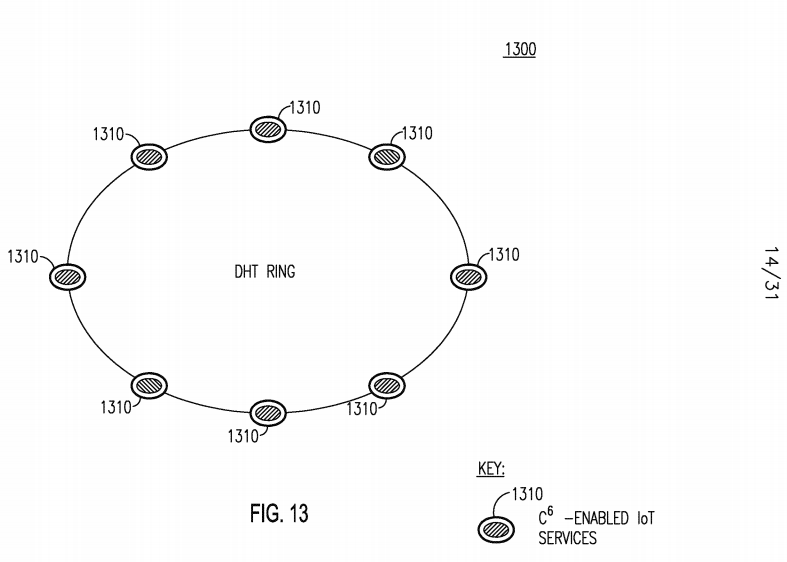
[0129] IoT services may be form non-P2P structures too. In this case, each IoT service may play different roles such as server-type service, client-type service, or proxy-type service. Server-type services may act as a master to provide services to other IoT services including client-type services and proxy- type services. Client-type services may act as a client to receive services from other IoT services including server-type services and proxy- type services. Proxy- type services may act as intermediaries to provide services to other IoT services (for example client- type services and proxy-type services), and in the mean time may receive services from other IoT services (for example server-type services and proxy-type services).
[0130] If an IoT Entity does not host a particular C6-enabled IoT service that it needs, a C6 IoT architecture may allow an IoT Entity to collaborate with other IoT Entities who do host the desired services, as illustrated in Figure 14. Figure 14 shows an example C6 IoT service architecture 1400 that provides IoT Entity collaboration to share C6-enabled IoT services 1410i-io. In this example, three IoT Entities are shown, 1405A, 1405B, and 1405c. Each IoT Entity 1405A C may host its own C6-enabled IoT services 1410i-io but may also use a set of services 1410i-io hosted on other IoT Entities.
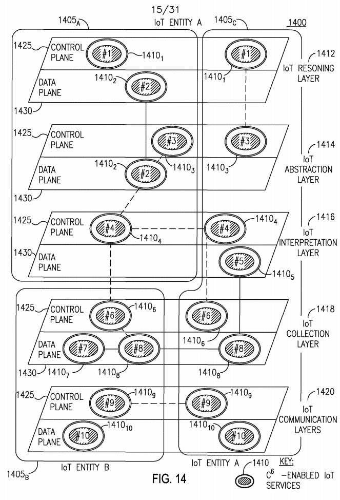
[0131] Some C6-enabled IoT services 1410i-io may be localized within a specific layer, while others may span across layers, the layers including: IoT Reasoning Layer 1412, IoT Abstraction Layer 1414, IoT Interpretation Layer 1416, IoT Collection Layer 1418, and IoT Communication Layer 1420. Additionally, the services 1410i-io may exist in either the Control Plane 1425 or the Data Plane 1430. For example, IoT Entity 1405A may host IoT services 1410i- 4 spanning across the Reasoning Layer 1412, the Abstraction Layer 1414 and the Interpretation Layer 1416. IoT Entity 1405c may host IoT services 1410i,3,4,5,6,8,9,io spanning across all layers 1412-1416.
[0132] Some of the services 1410i-io may function in an isolated manner, while others may collaborate with other services 1410i-io. C6-enabled IoT services 1410i-io of the same type may collaborate either within the same Entity or between Entities 1405A C- For example, service 14104 hosted on Entity 1405A may collaborate with service 14104 hosted on Entity 1405c (illustrated by the dotted line). Within Entity 1405A, service 14102 in the IoT Abstraction Layer 1414 may collaborate with service 14102 in the IoT Reasoning Layer 1412. Similarly, services 1410i-io of different types may collaborate. For example, service 14102 hosted on Entity 1405A in the Abstraction layer 1414 may collaborate with service 14103 also in the Abstraction Layer 1414 and with service 14104 in the Interpretation layer, both also hosted on IoT Entity 1405A.
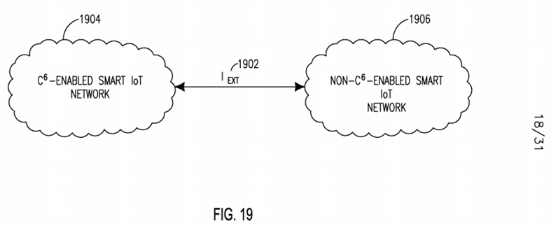
[0133] The SMART C6 IoT architecture may include any of the following interfaces: Ic e, which is the Interface between C6-capabilities and is illustrated in Figure 15; Ic-s, which is the Interface between a C6-capability and a C6- enabled IoT service and is shown in Figure 16; Is-s, which is the Interface between C6-enabled IoT services and is shown in Figure 17; IS A, which is the Interface between a C6-enabled IoT service and an application and is shown in Figure 18; and IEXT, which is the Interface between a C6-Enabled Smart IoT Network and non-C6-Enabled Smart IoT Network and is shown in Figure 19. These Interfaces are described in further detail below.
[0134] Figure 15 shows the Ic e interface 1502 between two individual C6 capabilities 1506. The Ic e interface may perform the following functionalities: support cross-capability collaboration; and support communications between two C6 capabilities in a peer-to-peer and/or client- to- server model.

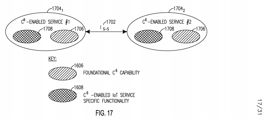
[0135] Figure 16 shows the Ic s interface 1602 between an IoT Service 1604 and a C6 capability 1606. The Ic s interface 1602 may provide support for interfacing a C6 capability 1606 to an IoT service 1604 to enable it with C6 service specific functionality 1608. Figure 17 shows the Is-s interface 1702 between Two Individual C6-Enabled Services 1704i and 17042. The Is-s interface may support cross-service collaboration, and may support communications between two C6-enabled IoT services 1704i and 17042 in a peer-to-peer and/or client-to-server model. The C6-enabled IoT services 1704i and 17042 may each support foundational C6 capability 1706 and may have C6-enabled IoT service- specific functionality 1708.

[0136] Figure 18 shows the IS A Interface 1802 to support software programmability. The IS A Interface 1802 may enable software programmability of C6-enabled IoT services 1804, and indirectly foundational C6 capabilities 1806. This allows for externally configuring C6 functionality 1808 and services 1804, for example, by an IoT Application 1810 such as, for example, a network operator or administrator application. The Ic s interface 1812 between the IoT service 1804 and foundational C6 capability 1806 is also shown. For example, external configure of C6 functionality 1808 via the IS-A Interface 1802 may include configuring Cognition capability policies or cognition engine, collecting context from Context capability, or Configuring the Connectivity capability's routing table.

[0137] Figure 19 shows the IEXT Interface 1902 between a C6-enabled SMART IoT Network 1904 and other non-C6-enabled SMART IoT networks 1906. The IEXT interface 1902 may enable interfacing a SMART C6-enabled IoT network 1904 to other IoT networks 1906. Via this interface 1902, the capabilities and services supported within a SMART C6-enabled IoT network 1904 may be interfaced to the capabilities and services supported in other networks 1906.
[0138] Figure 20 shows an example protocol stack view 2000 of a SMART C6 IoT architecture. The C6-Enabled protocol stack 2000 may be hosted on an IoT Entity (not shown). The stack 2000 may include some traditional protocol stack layers illustrated within the IoT Communication Layers 2002, including: Transport Layer 2004, Network Layer 2006, medium access control (MAC) layer 2008, and Physical (PHY) Layer 2010. The stack 2000 may also include the IoT Reasoning Layer 2012, IoT Abstraction Layer 2014, IoT Interpretation Layer 2016, and the IoT Collection Layer 2018. These layers may interact with IoT Applications 2020.
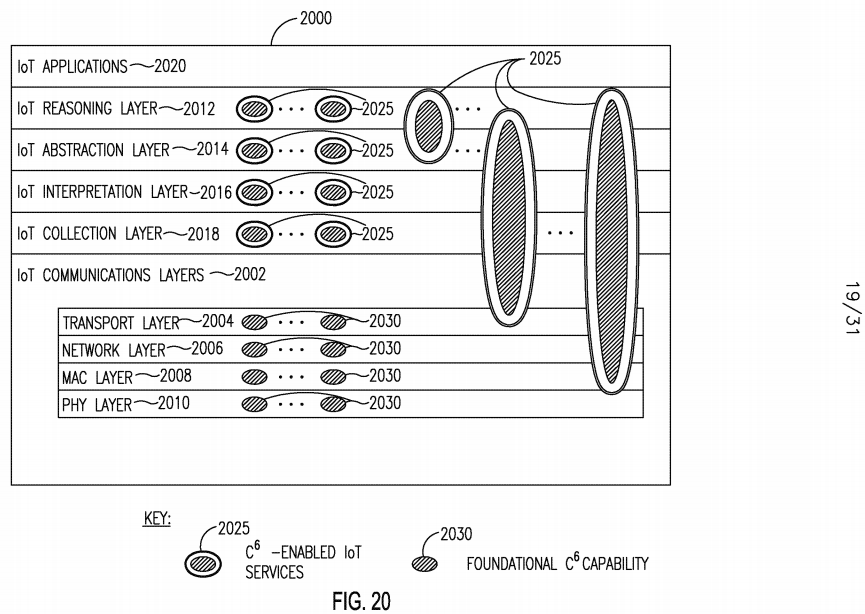
[0139] One or more C6-Enabled IoT services 2025 (which may themselves include foundational C6 capabilities 2030) may be localized within any protocol layer 2002-2018 and may offer services that are localized within that corresponding layer. Similarly, foundational C6 capabilities 2030 may be localized within any protocol layer 2002-2018. A service 2025 or capability 2030 may also span across protocol layers and offer cross-layer based functionality. The layers are described in further detail below. [0140] The IoT Communications Layers may provide C6-enabled intelligent communication between IoT Entities. C6-enabled services may be leveraged to improve communication quality of service (for example, through collaborative communications), and may provide communication connectivity as a service. The IoT Collection Layer may provide C6-enabled intelligent delivery, discovery, storage and caching of IoT data or information among IoT Entities, which may be unicast, anycast, multicast, and/or broadcast. C6-enabled services may be exploited to enhance data delivery performance based on content-aware technique such as, for example, content-aware data concatenation and/or aggregation. IoT data may be, for example, raw sensory data, reverse control commands, low-level context, or IoT-related policies.
[0141] The IoT Interpretation Layer may provide C6-enabled semantic modeling of the raw data collected from the IoT Collection layer. It may provide appropriate coverage and comprehensive representation of concepts and terms for describing entities and relationships among them. It may ensure semantic non-ambiguity and expressiveness with balanced processing complexity and semantics modeling language interoperability. The IoT Abstraction Layer may provide C6-enabled embedding/extracting of low-level context in/from IoT data. Data annotation, compression, and deep aggregation may also be performed in this layer. The output of the IoT Abstraction Layer may be low-level context abstracted from the semantics information of the IoT Interpretation Layer of the IoT Entity itself or from IoT Entities.
[0142] The IoT Reasoning Layer may provide C6-enabled data mining and analytics and may perform higher-level decision-making and intelligence based on IoT context and policies. Through data analytics, meaningful knowledge such as patterns, relations, perceptions, and context may be obtained from raw data and/or abstract data, which might be from other IoT Entities. C6-enabled services may be utilized to facilitate and enhance data analytics to provide better IoT data intelligence. [0143] Figure 21 shows an example of a relationship 2100 between a SMART C6-enabled IoT protocol stack 2104i-2 and different IoT Entities 2102i-2. The IoT protocol stack 2104i_2 in IoT Entities 2102i_2 each respectively include an IoT Reasoning Layer 2106i-2, IoT Abstraction Layer 2IO81-2, an IoT Interpretation Layer 2I IO1-2, an IoT Collection Layer 2112i_2, and an IoT Communication Layer 2114i-2, in addition to IoT Applications 2I I61-2. The IoT Collection Layers 2112i_2 of the IoT Entities 2102i_2 may collect the raw data 2118 from the physical world 2120 through the IoT infrastructure, and may communication with each other. In an example, temperature sensors may be making temperature readings. The IoT Collection Layers 21121-2 may receive the raw data 2118 of the temperature from the Communications Layers 2114i_2. The IoT Interpretation Layers 2I IO1-2 may interpret the semantics 2125 of the raw data 2118, such as, for example, its units, location and time that it was collected, among other things. The IoT Abstraction Layers 2IO81-2 may generate low-level context 2130 such as, for example, the average temperature in the current location in a certain month, using the output from the IoT Interpretation Layer 2I IO1-2 from one or both IoT Entities 2102i_2, as illustrated with arrows. For example, IoT Entity 2102i may receive semantic information 2125 from both Interpretation Layers 2I IO1-2 in both Entities 2102i_2. In this case, IoT Entity 21022 may be, for example, another sensing device in the same neighborhood.

[0144] The IoT Reasoning Layer 2106i may receive low-level context 2130 from either Entity 2102i_2 to calculate high-level context 2135. In an example, the IoT Reasoning Layer 2106i may use the average temperature to find out whether the temperature is above some threshold, such as whether it is more than 100 degrees Fahrenheit. The IoT Reasoning Layer 2106i in Entity 2102i may generate high-level context 2135 that, for example, the location is under a high temperature alert. Such an event may be generated for the IoT Application Layer 2116i to take action, such as, for example, to enforce human-induced rainfall. The actions may in turn change the physical world 2120, such as decreasing the temperature. The new raw data 2118 may be sensed and the cycle may continue.
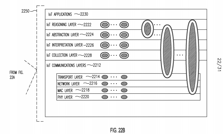
[0145] Figures 22A and 22B shows an example of a C6-Enabled IoT Protocol Stack 2250 Deployment 2200. Numerous IoT Entities 2202i...6 are deployed, including, for example, gateways, servers, and devices. These entities 2202i...6 may interact with end-users 2204. Each entity 2202i...6 is illustrated as supporting one or more of the following protocol stack layers: Communications Layer 2212, Transport Layer 2214, Network Layer 2216, medium access control (MAC) layer 2218, Physical (PHY) Layer 2220, IoT Reasoning Layer 2222, IoT Abstraction Layer 2224, IoT Interpretation Layer 2226, and the IoT Collection Layer 2228. These layers may interact with IoT Applications 2230, and may support C6-enabled IoT services 2206, independently or across multiple layers.
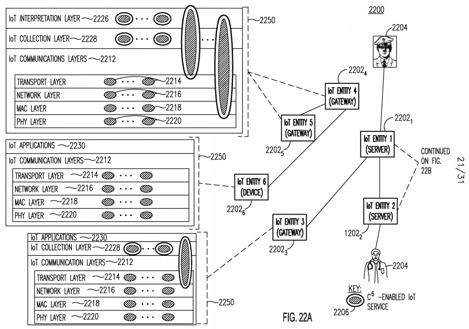
[0146] As shown in Figures 22A and 22B, depending on the level of functionality and capabilities, some IoT Entities 2202i...6 may not support all layers of the proposed C6-Enabled protocol stack 2250 in a deployed IoT system. Communication layer 2212 and collection layer 2228 may be considered two basic layers, while other layers may provide value-added IoT services 2206 but may not be needed by certain IoT Entities 2202i...6. For example, IoT Entity 2202i supports all layers, but IoT Entity 22023 supports simple data collection 2228 but not other layers such Interpretation 2226 and Abstraction 2224. In addition, IoT Entities 22024 and 2202s are gateways and may support more layers and functionalities than IoT Entity 2202β, which is a device.
[0147] Diverse information may exist in IoT systems and may flow, for example, from one IoT Entity to another IoT Entity, from one C6-enabled IoT Service to another C6-enabled IoT Service, or from one protocol layer to another protocol layer. IoT information may be categorized into content, context, policy, decision, event, discovery and descriptor information elements. Content may be any textual, visual or aural object in the IoT. Context may be any information that may be used to characterize the situation of an entity. A policy may be information describing a principle or rule to guide decisions and achieve rational outcomes. A decision may be made by the Cognition capability to give demand or instruction for taking actions.
[0148] An event may refer to many things such as, for example, an observable occurrence, phenomenon, or extraordinary occurrence, to name a few. A discovery element may contain the result of a discovery query. A descriptor may describe the attributes of an IoT Entity, Service or Application. IoT Entity, Service and Application may be considered operable elements in the IoT. In order to be able to discover, address and operate on these elements, descriptors which describe the attributes of the elements may be useful. The IoT Entity descriptor, Service descriptor, and Application descriptor may be considered one class of IoT information. Those different types of information may not be fully dependent of each other, but may have certain relationships or dependencies among them.
[0149] Figure 23 shows the relationships 2300 among the information elements of content 2301, context 2302, policy 2303, decision 2304, event 2305 and discovery 2306. In Figure 23, several exemplary relationships are illustrated; however other relationships between the information elements 2301- 2306 that are not shown may also exist. Content 2301, context 2302, policy 2303, decision 2304 and event 2305 may generate new content 2301. The context 2302 may be derived 2309 from the content 2301, or/and other contexts 2302. An event 2305 may generate 2310 new context 2302. A policy 2303 or a decision 2304 may generate or change 2312 the context 2302. Context 2302 may influence 2314 policy 2303 and decision 2304. Policy 2303, event 2305 and decision 2304 may generate 2310 new policies 2303. For example, a decision 2304 may be made with the influences 2314 from context 2302, other decision 2304, policy 2303 and event 2305. Changes in context 2302, decision 2304, policy 2303 and other events may trigger 2316 a new event 2305 to occur. Discovery 2306 may contain the search result of certain content 2310, which may relate to 2318 content 2310. Any change in the content 2310 itself, for example its location or format, may invalidate 2320 any cached discovery 2306 information.
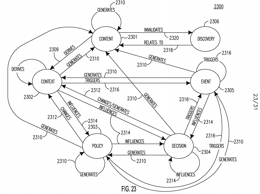
[0150] Figure 24 shows the relationship 2400 among IoT Entity 2402, Service/Capability 2404 and Application 2406 and other IoT information categories, which include Content 2408, Context, 2410, Policy 2412, Decision 2414, Event 2416, and Discovery 2418. An IoT Entity 2402 may be, for example, a router, gateway, or device. In the Figure 24, the arrows represent the containing relationships. An IoT Entity 2402 may contain application 2406, service 2404, content 2408, context 2410, policy 2412, decision 2414, event 2416 and discovery 2418. Policy 2412 and Decision 2414 together may form the cognition capability. An Application 2406 and Service 2404 may contain content 2408, context 2410, policy 2412, decision 2414, event 2416 and discovery 2418. The overview of the contained information elements may be shown inside the descriptor of each of the respective IoT Entity 2402, the Service/Capability 2404 and the Application 2406.
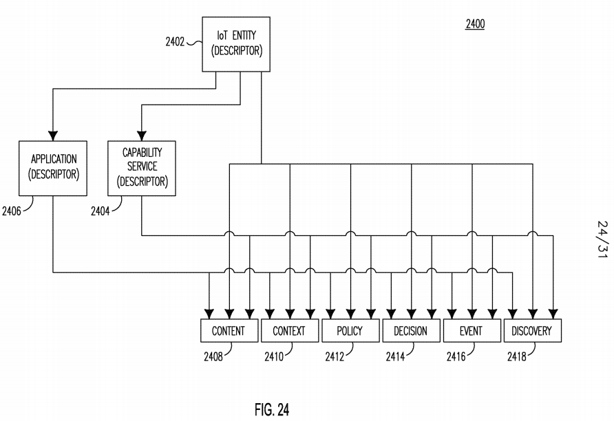
[0151] An IoT may be designed to jointly optimize different combinations of the C6 capabilities including connectivity, content, cloud, cognition, context, and collaboration. Below are several examples. For example, connectivity and content may be jointly optimized by performing effective content and/or data collection over diverse connectivity. Connectivity may be adapted for content, for example, by using low latency connectivity for delay- sensitive content, or using reliable connectivity for loss-sensitive content. Data may be adapted for connectivity, for example, in- network data aggregation and compressive sensing may be used to reduce data volume for low data rate connectivity.
[0152] In another example, connectivity and cloud may be jointly optimized. For example, connectivity may be provided in a cloud, by leveraging network/link virtualization including, for example, base station virtualization and virtual mobile network operator (VMNO). In another example, a cloud may be connectivity-enabled for computation offloading, where local computation tasks may be Offloaded to the cloud to save energy-consumption especially for computation-intensive tasks where communication-related energy consumption may be much lower than that resulted from computation.
[0153] In another example, connectivity and cognition may be jointly optimized. Enhanced connectivity may be achieved via cognition. Examples include: software-Defined Radio using such standards as IEEE 802.22, IEEE 802.11ah, or IEEE 802.15.4m; software- defined optics using adaptive and flexible optic resource allocation (for example optic wavelength and spectrum, modulation scheme); and software- defined networks, for example, where network behavior may be adaptively reconfigured via software, and where virtual networks may be formulated dynamically.
[0154] In another example, connectivity and context may be jointly optimized, for example, by performing context-aware smart connectivity. In an example, context-aware offloading may involve making an offloading decision based on user/device's context, for example, by preventing a fast moving device offload from cellular to WiFi. Context-aware routing may dynamically adjust routing in sensor networks based on residual energy at each sensor node so that each node has close residual energy and which in turn may prolong overall network lifetime. In addition, context-awareness may be leveraged for bandwidth management such as to assist in making better decision on whether to enable direct WTRU-to-WTRU communications in cellular networks. In this case, the context may be potential radio interference or energy consumption, for example.
[0155] In another example, connectivity and collaboration may be jointly optimized to leverage collaborative communication and networking to create smart connectivity. One example is joint design of "application layer + network (NWK)/MAC layer" for video over wireless by letting high-importance or base video frames be transmitted with higher priority. Examples of cross-node collaboration include relay-based communications, virtual multi-input- multi- output (MIMO) communications, Coordinated Multi-Point (CoMP) in wireless communications, and P2P file sharing. Examples of cross-network collaboration include: using femtocell to offload macrocell traffic; using femtocell backhaul to offload mobile backhaul; using broadcast wireless networks to assist line-of-sight networks by transmitting control messages; multiple networks sensing; and selection and handover.
[0156] In another example, content and cloud may be jointly optimized, such as by cloud-based content storage. For example, content copies may be stored in different places in a cloud to improve reliability. Also, chunks of the same content may be stored in different places in the cloud to improve security. Critical and/or less popular content may be stored in a local private cloud while less important and/or more popular content may be stored in a public core cloud. In an example of cloud-based semantic services, content itself may be a kind of services. Putting contents in the cloud may enable content correlation and/or analysis to in turn provide semantic services.
[0157] In another example, content and cognition may be jointly optimized. Examples include: a cognitive radio map including for example location, time, channel Id, availability flag; analyzing contents to get cognition; and use learned knowledge to improve content management. In another example, content and context may be jointly optimized. In an example of semantic data modeling, context/semantic information may be used for content modeling. In an example of semantic content discovery, the handling of context- aware/semantic content discovery may be determined. In an example of context-aware Content Adaptation, context information may be leveraged to perform intelligent context adaptation such as, for example, delivery of different context representations and/or formats for different users, or converting content (for example video/audio transcoding) along a transmission path.
[0158] In another example, content and collaboration may be jointly optimized.
[0159] In an example of distributed data storage/cache, content may be collaboratively stored/cached in different locations in a distributed fashion. In an example of data aggregation, content aggregation may involve collaboration among participating nodes. In an example of social/participatory sensing or "crowdsensing", people may use their smart phone to sense the world/environment together, and may share sensed information.
[0160] In another example, cloud and cognition may be jointly optimized.
For example, cognitive radio or wireless/mobile clouds may rely on mining and learning from large volumes of data, which need high computing and storage utility. Such challenges may be overcome by leveraging cloud. Mobile terminals with multiple different air interfaces may autonomously utilize the most appropriate infrastructure wireless networks by sensing available wireless networks, finding the most appropriate configuration set, and reconfiguring themselves seamlessly to the selected set. For optimization of radio resource management of such a scalable network having multiple operator networks and terminals, distributed optimization and management methods may be applied to keep using the most appropriate wireless configurations adaptively.
[0161] In another example, cloud and context may be jointly optimized. In an example of context-aware offloading, an offloading decision may be made based on a user's or device's context. For example, context may be used to prevent a moving device from offload from cellular to WiFi. In an example of context as a cloud service, context information management may be performed and may include context information modeling, collection, and access.
[0162] In another example, cloud and collaboration may be jointly optimized. In an example of edge cloud collaboration, collaboration may exist between edge cloud and core cloud, among edge clouds, or among core clouds. In an example of distributed data storage, content may be collaboratively stored/cached in different locations in a distributed fashion.
[0163] In another example, cognition and context may be jointly optimized. As an example of context from cognition, knowledge/context information may be learned from raw data via data analytics. In an example of context-aware cognitive networking, a cognitive radio map may be used as a kind of context and leveraged for routing in multi-hop cognitive ad hoc networks. Additionally, other context information such as, for example, primary user activity history, may be leveraged for fast channel sensing to quickly locate an available channel.
[0164] In another example, cognition and collaboration may be jointly optimized. An example of cognitive collaborative networking is collaborative sensing, where nodes may collaboratively sense channel availability by reporting raw sensed info to a fusion center or reporting local decision to a fusion center. In another example, context and collaboration may be jointly optimized. In an example of context- aware collaborative networking, context information (such as residual energy, link quality, content importance) may be used to determine and select best "helpers" or relay nodes.
[0165] The C6 IoT architecture, C6 capabilities and C6-enabled IoT services may be integrated with and/or layered over different categories of network technologies such as ETSI M2M/oneM2M service layers, IETF protocols, CDN-based networks, and Cloud-based networks. An example of the ETSI TC M2M network technology adapted to the C6-enabled architecture is described below.
[0166] Relative to the C6-enabled IoT architecture, the ETSI TC M2M architecture has several shortcomings. For example, the TC M2M architecture may be centralized in nature. For example, the Network Service Capability Layer (NSCL) may be a centralized node in the architecture. The TC M2M architecture may not support content-aware, context-aware, collaborative, cloud- based, and cognitive functionalities. The M2M architecture may support a limited set of services, and may not support new services in the C6-Enabled IoT such as, for example, software-defined IoT service capability (SC), Virtualization SC, Service Delivery and Composition SC, Sensing/Actuating Management SC, Mobility Management SC, Event Management SC, and Communication and QoS SC. The TC M2M architecture may not specify interfaces and interactions between two services (i.e. M2M service capabilities). The M2M architecture may not support semantic modeling for content. Instead, the data may be opaque to the Service Capability Layer (SCL). Without semantic modeling support, the SCL may not understand the meaning of the data, or the relationships among data, applications, devices and users.
[0167] Moreover, in the TC M2M architecture, the routers between one SCL to another SCL may only carry out IP-based routing. With the hybrid host and content based routing at the IoT communication layer under the C6-enabled IoT architecture, the en-route router may be able to reply to some of the content requests if they are already cached. The TC M2M architecture may be lacking support for intelligent policies and cognition engine to help make decisions to regulate activities or interactions such as, for example: in connectivity (including offloading, routing, or bandwidth management), content (for example, when to cache content, or how to do the cache collaboration), context (for example, rules on context reasoning), collaboration (for example, inter-SCL collaboration on storage optimization), cloud (for example, when to offload some service to the cloud, inter-cloud collaboration). The C6-enabled SMART IoT architecture includes that polices may be managed by an SCL in the resource tree, such that the policies may be created, updated, deleted and retrieved, such that the policy database in the C6-enabled SMART IoT architecture may be mapped to the SCL resource structure.
[0168] The ETSI TC M2M architecture may be lacking support for dynamically composing or creating new services. One example is the context service, which may allow the applications or clients to create locally generated contexts to the SCL to be discovered and shared by others, or which may allow the SCL to compose higher level context from lower level context (IoT reasoning layer). The ETSI TC M2M architecture may also lack virtualization functions in the SCL. For example, the ETSI M2M architecture may be lacking support for virtualizing IoT objects, applications, resources, or services within the SCLs. In addition, support for virtualizing one SCL by another SCL may also be lacking.
[0169] The C6-Enabled SMART IoT architecture may be leveraged to enhance the ETSI M2M architecture as described in the following. Content- aware, context-aware, collaborative, cloud-based and cognitive functionalities may be integrated into the M2M architecture. Figure 25 shows an example of a C6-Enabled SMART ETSI M2M Architecture 2500 with C6 enhancements interacting with a C6-enabled IoT Architecture 2502. The M2M C6-enabled architecture 2500 includes M2M Applications 2518, M2M Device SCL (DSCL) 2504, Gateway SCL (GSCL) 2504, M2M Server SCL (NSCL) 2506, M2M Router 2516, and M2M Network Application (NA) 2514. M2M service capabilities (SCs) 2508 and C6-enabled IoT SCs 2510 may be implemented in M2M SCLs 2504/2506 and M2M routers 2516, and may communicate with each other using the IoT Isc- sc interface 2512. An M2M SC 2508 may directly communicate with another M2M SC 2508 via IoT Isc-sc interface 2512. An M2M SCL 2504/2506 and/or each M2M SC 2508 may communicate with an M2M Router 2516 or any service 2510 in the M2M Router 2516. M2M Applications 2518 may interact with SCLs 2504/2506 using the M2M dla interface 2520, SCLs may communicate over the M2M mid interface 2522, and M2M NAs 2514 may interact with SCLs 2504/2506 over an M2M mla interface 2524.
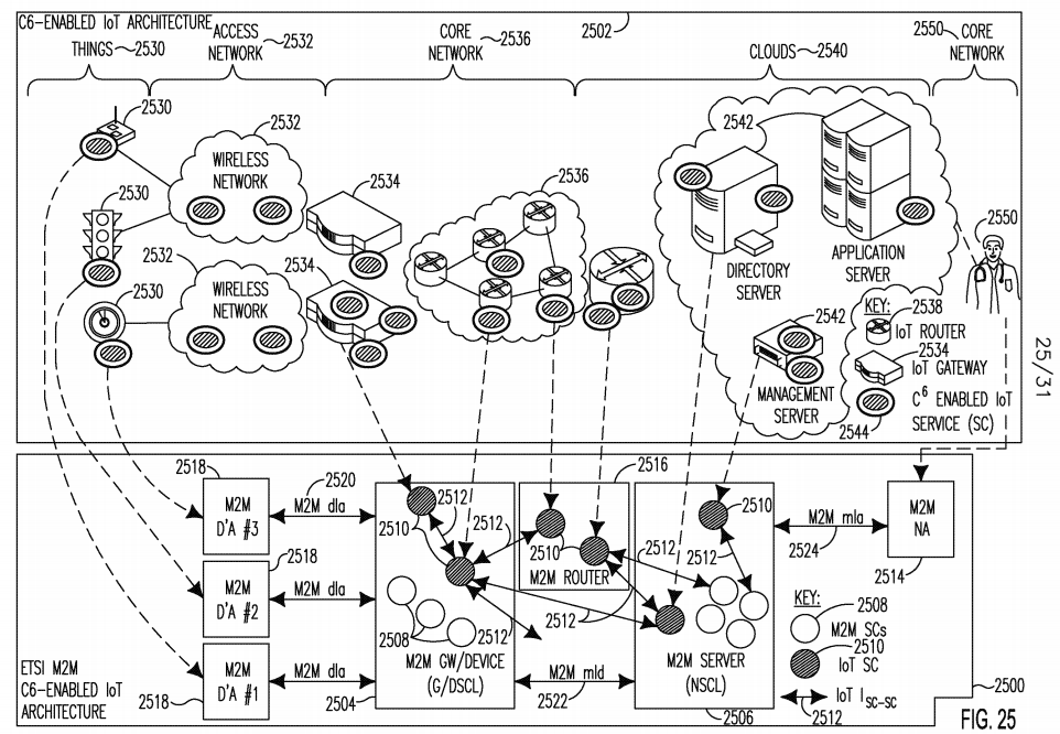
[0170] A C6-enabled IoT architecture 2502 may interact with the M2M C6- enabled architecture 2500. The C6-enabled IoT Architecture 2502 may include things 2530 (e.g. traffic lights, temperature sensors), access networks 2532 such as wired or wireless networks 2532, IoT Gateways 2534 connecting access networks 2532 to core networks 2536. Core networks 2536 may include IoT routers 2538, and routers 2538 may connect core networks 2536 to clouds 2540. Clouds 2540 may interact with applications/users 2550, and may include servers 2542, for example, directory, application or management servers 2542. Things 2530, access networks 2532, gateways 2534, core networks 2536, routers 2538, clouds 2540, and servers 2542 in the C6-enabled IoT architecture 2502 may interact and communicate with the M2M C6-enabled IoT architecture 2500 via the IoT SCs 2510. Any of things 2530, access networks 2532, gateways 2534, core networks 2536, clouds 2540, or servers 2542 may be equipped with various C6- enabled IoT service capabilities 2544. [0171] In the M2M C6-enabled architecture 2500, IoT C6-enabled IoT service capabilities (SCs) 2510 may be introduced into any M2M SCL such as, for example, the M2M Device SCL (DSCL) 2504, Gateway SCL (GSCL) 2504, and/or M2M Server SCL (NSCL) 2506 as new M2M SCs 2508. The Isc-sc interface 2512 may be used for communication between IoT SCs 2510 and other IoT SCs 2510 or M2M SCs 2508. Three examples for implementing C6-based M2M SCs are shown in Figures 27, 28, and 29, as will be discussed further below.
[0172] Direct interface and interactions between two SCs 2508/2510 may be enabled over the Isc-sc interface 2512 so that any SC 2508/2510 or SCL 2504/2506 may talk to other SCs 2508/2510 or SCLs 2504 or 2506 to enable a distributed architecture. A benefit of this type of design is data path optimization. For example, with direct interactions between SCs 2508/2510 or SCLs 2504/2506, communications from an M2M network application (NA) 2514 to an M2M device 2504 may directly bypass an M2M server 2506 on the data plane.
[0173] An M2M router 2516 may be introduced into the M2M architecture 2500. M2M router 2516 may have a limited SCL to support control plane functionalities such as assisting service discovery. M2M router 2516 may perform data plane message forwarding, caching, QoS scheduling, or aggregating at the service layer. M2M router 2516 may perform control plane functionalities such as, for example, assisting service discovery, and it may perform data plane functions such as, for example, QoS scheduling. M2M applications 2518 and M2M D/GSCL 2504 may not register with the M2M router 2516, while M2M NSCL 2506 may register with the M2M router 2516 so that M2M router 2516 may serve for a specific kind of M2M applications 2518. Either M2M applications 2518 or M2M SCL 2504/2506 may not actively create resources at the M2M router 2516, but the M2M router 2516 itself may create certain resource to facilitate caching and other functionalities it supports. M2M routers 2516 may talk to each other (not shown). M2M routers 2516 may be managed and controlled by a management application 2518 or authority. [0174] The following are examples of C6-enabled IoT SCs 2510 that may be introduced to an M2M SCL 2504/2506 or an M2M router 2516. A Content Management SC may provide semantic content awareness/modeling, including content identification, content searching and discovery, content adaptation, and differentiated content delivery, among other things. A Context Management SC may provide, for example, context collection, analysis, reasoning, and/or access, among other things. A Collaboration SC may provide collaboration between M2M SCLs 2504/2506 or M2M applications 2518. A Cloud Enablement SC may provide cloud services, cloud storage, cloud security, or computation offloading, among other things. A Cognition SC may provide semantic and context based learning, policy-based adaptive reasoning and decision making to support other service capabilities. It may configure policies in other SCs 2508/2510 or SCLs 2504/2506. A Connection Management SC may manage service connection between two SCs 2508/2510 or between two SCLs 2504/2506.
[0175] The above examples of C6-enabled SCs may serve as a foundation for enabling the ETSI TC M2M C6-enabled architecture 2500 to support higher- level services. The following are examples of higher-level SCs that may be realized by layering additional functionality on top of the C6-enabled IoT SCs 2510 described above. Some of these higher-level SCs are also discussed with respect to Figures 27, 28 and 29. With reference to Figure 25, a Service Publishing SC may publish an application or a service from an M2M application 2518, SCL 2504/2506, or SC 2508/2510 to other SCLs 2504/2506, or SCs 2508/2510. A Service Discovery SC may perform discovery of an M2M service 2508 based on semantic context information. A Service Negotiation SC may perform negotiation of services 2508 to be delivered to a service requestor.
[0176] A Service Delivery SC may perform delivery of services from one M2M application 2518, SCL 2504/2506, or SC 2508/2510 to another. A Service Composition SC may create or compose a new service based on low-level services. Service Adaption SC may adaptively change and optimize the delivery behavior of a service such as content format change and service host change. A Software Defined SC may dynamically program and configure M2M applications 2518, SCLs 2504/2506, or SCs 2508/2510. A Virtualization SC may create and manage virtualized IoT objects, resources and services within the M2M SCLs 2504/2506. A Sensing and Actuating Management SC may optimally manage sensing and actuating tasks to enable sensing infrastructure sharing and human-assisted sensing. Capabilities defined in C6-enabled sensing and actuating management SC may be leveraged.
[0177] An Event Management SC may perform intelligent event management based on context and semantic information. A QoS Management SC may perform management of service delivery QoS including QoS requirement feeding, QoS monitoring, and QoS enforcement. A Mobility Management SC may manage M2M service mobility such as service source mobility, service destination mobility, and/or host SCL mobility, among other things.
[0178] Figure 26 shows examples of C6-enabled M2M Protocol Stack Enhancements 2600 that may be included in any M2M SCL or M2M router. The C6-enabled IoT Layers may be implemented over M2M 2601 or embedded in M2M 2602. In the "over" implementation 2601, the C6-enabled IoT interpretation layer 2620, abstraction layer 2622, and reasoning layer 2624 may be added on top of M2M service layer 2610 and communication layer 2608. In the embedded implementation 2602, C6-enabled IoT interpretation layer 2614, abstraction layer 2616, and reasoning layer 2618 may be embedded into the M2M service layer 2606 as "sub-layers", to provide advanced services. A C6-enabled collection sub-layer 2612 may also be included in the C6-enabled M2M service layer 2606, and a C6-enabled communication layer 2604 may sit below the service layer 2606. Under either implementation 2601/2602, the M2M service layer 2606/2610 and low communication layer 2604/2608 may be enhanced by using C6-enabled IoT service capabilities 2630 within or across any of the layers 2604-2624.

[0179] Figures 27, 28 and 29 show example architectures to leverage C6 SCs. In the example architecture 2700 of Figure 27, SCs 2701-2716 may reside in the cloud 2720. SCs 2701-2716 were discussed above with respect to Figure 25 and may include any of: software- defined SC 2701, virtualization SC 2702, event management SC 2703, sensing and actuating management SC 2704, mobility management SC 2705, QoS management SC 2706, service publishing SC 2707, service discovery SC 2708, service delivery SC 2709, service composition SC 2710, service adaptation SC 2711, content management SC 2712, context management SC 2713, cloud enablement SC 2714, collaboration SC 2715, and cognition SC 2716.

[0180] With reference to Figure 27, M2M Device SCL (DSCL) 2722, Gateway SCL (GSCL) 2724, and Network SCL (NSCL or Server) 2726 may support a service cloud interface 2725 to access the SCs 2701-2716 in the cloud 2720. The DSCL 2722 may interact with device applications (DAs) 2730, the GSCL 2724 may interact with Gateway Applications (GAs) 2732, and the NSCL 2726 may interact with network applications (NAs) 2734. The DSCL 2722, GSCL 2724, and NSCL 2726 may interact with each other over the mid interface 2736 [0181] The M2M NSCL 2726 may directly access SCs 2701-2716 via the service cloud interface 2728. M2M D/GSCL 2722/2724 may indirectly access SCs 2701-2716 via M2M NSCL 2726 or directly via service cloud interface 2728. As a result, any of the M2M SCLs 2722/2724/2726 may have additional functionalities to support the service cloud interface 2728. The service cloud interface 2728 may support interactions between a SC 2701-2716 and an M2M SCL 2722/2724/2726.
[0182] A SC 2701-2716 may discover an existing M2M SCL 2722/2724/2726. A SC 2701-2716 in the cloud 2720 may publish or announce its existence to an M2M SCL 2722/2724/2726. An SC 2701-2716 nay access, monitor, and/or control an M2M SCL 2722/2724/2726 and may dynamically configure its behavior and access its resource tree. The SCs 2701-2716 in the cloud 2720 may be shared and concurrently accessed by multiple M2M SCLs 2722/2724/2726. An M2M SCL 2722/2724/2726 may discover a SC 2701-2716 from the cloud 2720. An M2M SCL 2722/2724/2726, for example the NSCL 2726, may publish or announce itself to SCs 2701-2716 in the cloud 2720. An M2M SCL 2722/2724/2726 may access and leverage a SC 2701-2716 in the cloud 2720 to serve itself or its hosted M2M SCLs 2722/2724/2726.
[0183] The example architecture 2800 of Figure 28 shows a hybrid scheme where an M2M DSCL 2822, GSCL 2824, or NSCL 2826 may locally have one or more of the C6-based M2M SCs, while others continue to reside on the cloud 2820. For example, the following SCs may exist on the cloud and be accessed as described in Figure 27 through the service cloud interface 2828: software-defined SC 2801, virtualization SC 2802, event management SC 2803, sensing and actuating management SC 2804, mobility management SC 2805, QoS management SC 2806, service publishing SC 2807, service discovery SC 2808, service delivery SC 2809, service composition SC 2810, service adaptation SC 2811, content management SC 2812, cloud enablement SC 2814, and collaboration SC 2815. Context management SC 2813 and cognition SC 2816 may reside on an SCL 2822/2824/2826, for example on a NSCL 2826 which may be accessed by the DSCL 2822 and GSCL 2824 over the mid interface 2736. As in Figure 27, the DSCL 2822 may interact with DAs 2830, the GSCL 2824 may interact with GAs 2832, and the NSCL 2826 may interact with NAs 2834.
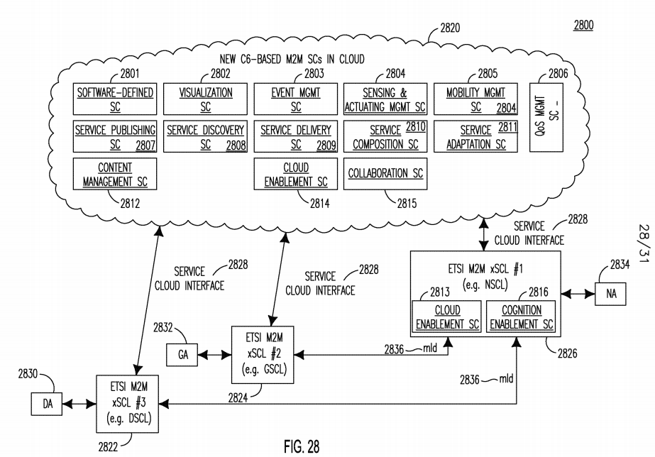
[0184] The example architecture 2900 of Figure 29 shows C6-based SC 2901-2916 may exist in each enhanced M2M xSCL 2920, including M2M D/G/NSCL, such that direct interfaces 2930 may used between C6-based SCs 2901-2916 and other M2M SCs 2935. None, some or all of the following SCs may be included on any SCL 2920: software- defined SC 2901, virtualization SC 2902, event management SC 2903, sensing and actuating management SC 2904, mobility management SC 2905, QoS management SC 2906, service publishing SC 2907, service discovery SC 2908, service delivery SC 2909, service composition SC 2910, service adaptation SC 2911, content management SC 2912, context management SC 2913, cloud enablement SC 2914, collaboration SC 2915, and cognition SC 2916. For example, an M2M NSCL 2920 may have all the SCs 2901-2916, while another M2M D/GSCL 2920 may not locally have certain SCs (for example, collaboration SC 29215), but may access the SC provided by the M2M NSCL 2920.

[0185] In the following, context-aware techniques for ETSI TC M2M C6-Enabled architectural enhancements are described pertaining to: flexible semantic operations over <contentInstance>; semantic operation cross containers; command-based semantic operation; and content-aware handling of big M2M data. For each operation of minimum (MIN), maximum (MAX), average (AVE), and summation (SUM), more information may be added to specify the range of the operation. For example, information such as how many <contentInstance> values should be considered may be added for calculating a MIN, MAX, AVE, or SUM value. An example of <contentInstance> is an instantaneous sensor reading such as a temperature value. For example, if there are 10 <contentInstance> values, it may be possible to calculate a maximum "MAX" over 3 of the <contentInstance> values. One solution for accomplishing this example calculation is to define two more sub -attributes, for example "startinglnstance" and "Count", for each operation MIN, MAX, AVE and SUM. In another solution, time may be used to specify or be indentified with a <contentInstance> value. For example, only calculate those <contentInstance> values whose creation time falls between Tstart and TstoP, where Tstart < Tstop, may be used in calculating the MAX of a subset of <contentInstance> values.
[0186] In an example of this, a building has 10 rooms, such that each room has a temperature sensor. Each temperature sensor may corresponds to a <container> in an M2M gateway (i.e. GSCL). Note that a <container> may contain one or more than one <contentInstance> Assume that it is desired to find out which room has the maximum temperature, or to calculate the maximum temperature over all rooms. To do this, a <group> resource may be defined for the group of rooms, and each of its members (i.e. rooms) is a <container>. The calculation MAX (similarly, MIN, AVE, and SUM) may be added as a new attribute to this <group>. An operation of MAX (similarly, MIN, AVE, and SUM) on <group> implies the calculation of a MAX (similarly, MIN, AVE, and SUM) value over all its members. In addition, MIN-MAX and MAX-MIN operations may be defined to find the minimum value of all maximum values within a container, and the maximum value of all minimum values of each container, respectively.
[0187] A resource of a super container <superContainer> may be used. Each super container may have multiple ordinary <container> or "containers" resource as its sub-resource. An operation of MIN/MAX/AVE/SUM on <superContainer> implies the calculation of a MIN/MAX/AVE/SUM value over all its sub-resources or <containers>. In an example of this, a room may have 3 sensors: temperature, smoke, and pressure. Each sensor may correspond to a <container> in an M2M gateway (i.e. GSCL). Assume it is desired to find out if the room has a fire or not, in which case information from a single sensor or <container> (temperature, smoke, or pressure only) may not be enough. Information from all sensors temperature, smoke and pressure may be used with application logic, or relations/semantics among those sensors (i.e. <container>).
[0188] The relationships among multiple <container> may be modeled, then the relationships may be leveraged to perform various operations. For example, a resource "contentSemantics" may be defined consisting of many "<contentSemantics>". Each <contentSemantic> may have a list of links pointing to existing <containers>. The relationships among those <containers> may be modeled as attributes or sub-resources of <contentSemantic>. Then, semantic operations may be defined based on those relationships.
[0189] M2M management commands may be leveraged to support semantic operations including MIN/MAX/AVE/SUM. For example, each semantic operation such as MIN or MAX may be modeled as a <command>. This <command> may be centrally placed, for example, under an <sclBase> tree. Note that <sclBase> is the root node of the entire resource tree at service layer for an M2M SCL as defined in ETSI TC M2M specification. This <command> may have a "link" attribute, which may be a pointer to an existing <container> or other resource. This <command> may be placed in a distributed manner as a sub- resource of a <container>, in which case the "link" attribute may not be required.
[0190] Regarding content-aware handling of big M2M data, video cameras may generate a video streaming file, which may be modeled as a <container> or <contentInstance>. If modeled as a <container>, <contentInstance> may be used to model different frames such as B-frames (bi-predictive picture), I-frames (intra-coded picture), or P-frames (predictive picture) by adding a new attribute "contentType" to indicate frame type and/or frame importance. Then, the importance of different <contentInstance> may be known and employed for content- aware optimization for accessing <contentInstance> and more intelligent service-layer content processing such as, for example, storage and replication.
[0191] In another example, a big file, for example raw data from a device/gateway, may be transmitted from an M2M Device/Gateway to an M2M Server, such that it may be difficult to pack the big file into one Constrained Application Protocol (CoAP) or hyper-text transfer protocol (HTTP) message. In this case, the file may be modeled as a <container> and each chunk of the file may be a <contentInstance>. A requester may specify the size of each chunk and may access particular chunks indentified by <contentInstance> in any order. Attributes such as, for example, "contentType", "blocklmportance", and "blockSequenceNumber" may be added to indicate the type of a block, the important of a block, and the sequence number of a block, respectively. Block- wise transfer at the M2M service layer using RESTful manner will be enabled.
[0192] The IETF Internet architecture and protocol may also benefit from C6 enhancements. For example, under the IETF IoT cloud framework, Internet architecture and protocols may lack support for a standard reference framework for cloud based IoT resources and services. Additionally, the following services and protocols may be lacking: IoT object cloud virtualization protocols for virtualizing physical IoT objects into virtual IoT objects (VOs) hosted in the cloud; protocols to allow IoT service developers to create IoT cloud resources & services; IoT cloud resources and services availability announcement/publishing protocol; IoT cloud resources and services directory/registrar discovery protocol; IoT cloud resources and services reservation protocol; IoT cloud resources & services authentication mechanism; IoT cloud resources & services privacy and protection mechanism; IoT cloud resources & services API such as, for example, cloud client- side API and cloud server-side API; IoT cloud resources & services description language; IoT cloud resources and services analytics and management protocol; and IoT inter-cloud resource and services spanning multiple providers, management domains such as, for example, protocols to support the mobility of virtualized IoT objects from one cloud domain to another.
[0193] The IETF Internet architecture and protocols may lack content awareness. For example, lack of application protocol that support semantic modeling and content awareness may be lacking. The data may be opaque to Internet protocols and without semantic modeling support, the protocols may not understand the meaning of the data, and the relationships among data, applications, devices and users. For example, routing protocols and transport protocols may lack content awareness and therefore may not support content- based routing or transport.
[0194] The IETF Internet architecture and protocols may lack context awareness and the ability to exchange IoT related context information between objects, network nodes (for example routers and cloud servers) and applications. For example, protocols may lack context awareness of IoT context such as sleep state, energy/battery level, geo-location, network or link congestion, or mobility context, among other things. Without context awareness, protocols may leverage this information to provide enhanced capabilities for IoT. For example, context awareness may be used to support intelligent proxying by network nodes such as routers and cloud servers, including, for example, proxy for IoT objects that are sleeping.
[0195] The IETF Internet architecture and protocols may be lacking support for intelligent policies and cognitive decision making to regulate activities or interactions such as in connectivity (for example, offloading, routing, and bandwidth management), content (for example, when to cache content or how to do the cache collaboration), context (for example, rules on context reasoning), collaboration (for example, inter-server collaboration on storage optimization), or cloud (for example, when to offload some service to the cloud, or inter- cloud collaboration).
[0196] IETF Internet protocols and architecture may lack software defined IoT networking capabilities. Such capabilities may be useful for IoT. For example, software may download a new application, service, policy update, or context information to an IoT object or IoT entity in the network such as a router or cloud server. The IETF architecture may also lack specific technologies for the management of constrained IoT objects and the networks comprised of constrained IoT objects. Certain IETF management protocols may be too heavyweight and may not have been designed for management of constrained IoT objects. Specifically, the following may be lacking in IETF Internet protocols and architecture: a simplified management protocol supporting energy- efficient communication, less CPU usage and small memory footprint; IoT object self- configuration and self-management; and efficient software distribution/configuration of IoT objects; management data models for IoT objects. Finally, IETF Internet architecture and protocols may be host centric and may not support content based addressing. Addressing and routing may be based on the physical address of a host. Support for addressing content residing on a host may be lacking.
[0197] The C6-Enabled SMART IoT architecture may be leveraged to enhance the IETF Internet architecture and protocols as described in the following. C6 functionality such as content-awareness, context-awareness, collaboration, cloud, and cognitive functionalities described above may be integrated into IETF protocols. C6-Enabled IoT service capabilities may also be overlaid and interfaced to IETF protocols and standardized interfaces may exist between them. [0198] For example, the C6-Enabled Virtualization Service may be leveraged to support virtualizing physical IoT objects into virtual IoT objects (VOs) hosted in the cloud. The C6-Enabled Software Defined Service and C6- Eabled Service Delivery and Composition Service may be leveraged to allow IoT service developers to create IoT cloud resources and services. The C6-Enabled Publishing, Discovery and Negotiation Service may be leveraged to support IoT cloud resources and services availability announcement/publishing protocol. The proposed C6- Enabled Publishing, Discovery and Negotiation Service may be leveraged to support IoT cloud resources and services directory/registrar discovery.
[0199] The C6-Enabled Publishing, Discovery and Negotiation Service may be leveraged to support IoT cloud resources and services reservation. The IS-A interface may be leveraged to support IoT cloud resources & services APIs such as, for example, cloud client-side API and cloud server-side API. The Service format of the C6 architecture may be leveraged to support a method for describing IoT cloud resources and services. The C6-Enabled Device Management capability may be leveraged to support IoT cloud resources and services analytics and management. The C6-Enabled Service Mobility Management capability may be leveraged to support IoT inter-cloud resource and services spanning multiple providers, and/or management domains.
[0200] IoT Content Awareness may be supported by enhancing IETF protocols (e.g. networking, routing, transport and application protocols) with the features of the C6 Content function. Examples include Horizontal Semantic Data Model for IoT Content, Hybrid Host and Content Based Routing, Cognition Based Content Services, Context Based Content Services, Content Collaboration, Cloud Based Content Services, Dynamic Content Adaptation & Enrichment. In addition, C6-enabled IoT content based services may be overlaid on top of C6- enabled IETF protocols to provide additional value-added features. Some examples include Data Collecting/Caching Service, Semantic Data Modeling Service, Data Mining & Analytics Service, and Data Fusion/Aggregation Service. [0201] IoT Context Awareness may be supported by enhancing IETF protocols (e.g. networking, routing, transport and application protocols) with the features of the C6 Context function. Examples include Cloud Based Context Services, Cognitive Context Management, Context Collaboration, Context Model Optimized For IoT, Context Discovery and Addressing, Context Delivery and Distribution, Context Adaption and Enrichment and Context Security. In addition, C6-enabled IoT context based services may be overlaid on top of C6- enabled IETF protocols to provide additional value-added features such as, for example, Context Modeling Service, and Context Management Service.
[0202] Policy Based IoT Networking may be supported by enhancing IETF protocols (e.g. networking, routing, transport and application protocols) with the proposed features of the C6 Cognitive function. Examples include support for a C6 Cognition Model, C6 Cognition Policy Database, Cognition Collaboration and Cloud Based Cognition Services. In addition, C6-enabled IoT policy based services may be overlaid on top of C6-enabled IETF protocols to provide additional value-add features such as, for example, Policy Management Service.
[0203] Software Defined IoT Networking may be supported by provided services such as, for example, C6- Enabled Software Defined IoT Service, C6- Enabled Service Delivery and Composition Capability and C6-Enabled Publishing, Discovery and Negotiation Capability by overlaying the services on top of IETF protocols. Interfaces between the overlay services and IETF protocols may be defined and standardized to allow information to flow between the IETF protocols and overlay services. These interfaces may leverage the IS-A interface described above.
[0204] IoT Management Protocols of IoT objects and networks consisting of IoT objects may be supported by enhancing IETF protocols (e.g. networking, routing, transport and application protocols) with C6 functionality to support the flow of network management information. For example, context information from the C6 Context capability such as congestion context may be collected from IoT objects in the network. C6 functionality may also be leveraged to provide finer and more intelligent control of IoT objects. For example, IoT objects may be managed by creating or configuring C6 Cognition capability policies. IoT Content Based Addressing may be supported using a content-based naming and addressing mechanism, and the content location resolution service of the C6 Content capability may also be leveraged.
[0205] Figure 30 shows an example of SMART 3GPP C6- Enabled IoT Architecture 3000 with C6 enhancements interacting with a C6-enabled IoT Architecture 3002. The 3GPP C6-enabled architecture 3000 may include devices such as User Equipments, which include Machine-Type communications (MTC) devices 3004 and non-MTC devices 3006 that may communicate directly with each other or via a 3GPP Radio Access network (RAN) 3008 such as a Long Term Evolution (LTE) network using a NodeB 3010 base station. The devices 3004/3006 may access a 3GPP core network 3012 via the 3GPP RAN 3008. An example of an MTC device 3004 is a 3GPP terminal installed on a car to monitor location of the car, while smart phones are examples of non-MTC devices 3006.

[0206] The core network 3012 may include entities such as Serving General Packet Radio Service (GPRS) Support Node (SGSN) 3014, Gateway GPRS Support Node (GGSN) 3016, mobility management entity (MME) 3020, mobile switching center (MSC) 3018, home subscriber server (HSS) 3024, and short message service (SMS) service center (SMS-SC) 3022. These entities may interface with the MTC Interworking Function (MTC-IWF) 3025, the Service Capability Server (SCS) 3026, and the application server 3027 either directly or indirectly.
[0207] A C6-enabled IoT architecture 3002 may interact with the 3GPP C6- enabled IoT architecture 3000. The C6-enabled IoT Architecture 3002 may include things 3030 (e.g. traffic lights, temperature sensors), access networks 3032 such as wired or wireless networks 3032, IoT Gateways 3034 connecting access networks 3032 to core networks 3036. Core networks 3036 may include IoT routers 3038, and routers 3038 may connect core networks 3036 to clouds 3040. Clouds 3040 may interact with applications/users 3050, and may include servers 3042, for example, directory, application or management servers 3042. Any of things 3030, access networks 3032, gateways 3034, core networks 3036, clouds 3040, or servers 3042 may be equipped with various C6-enabled IoT service capabilities 3044.
[0208] Things 3030, access networks 3032, gateways 3034, core networks 3036, routers 3038, clouds 3040, and servers 3042 in the C6-enabled IoT architecture 3002 may interact and communicate with elements of the C6- enabled 3GPP architecture 3000 directly or indirectly such as MTC devices 3004, non-MTC devices 3006, 3GPP RAN 3008, NodeBs 3010, 3GPP Core Network 3012 entities such as, for example, SGSN 3014 and GGSN 3016, MTC-IWF 3025, SCS 3026 and Application server 3027. C6 capabilities and C6-enabled services 3044 may be implemented in 3GPP radio access network 3008, and in NodeB/eNobeB/base stations 301 or in relays or repeaters (not shown) inside the 3GPP RAN 3008. For example, virtualization service may be implemented in a NodeB 3010 to support base station virtualization and sharing and access network virtualization and sharing. In another example, context-aware content caching and storage may be implemented in a NodeB 3010 to reduce network traffic load. C6 capabilities and C6-enabled services may be implemented in 3GPP core network 3012 entities such as, for example, SGSN 3014, GGSN 3016, MME 3020, MSC 3018, or HSS 3024. For example, context-aware content caching and storage may be implemented in 3GPP core networks 3012 (for example, evolved packet core (EPC) system) to reduce network traffic load and improve application quality.
[0209] Figure 31 shows an example of a content delivery network (CDN)- based SMART C6-Enabled IoT Architecture 3100. Figure 31 shows a service and content delivery architecture 3100 based on content distribution network and context-awareness and collaboration techniques. Content may be stored in different CDNs 3102i_3, where the CDNs 3102i_3 interact with each other as well as users/devices 3104. For example, there may be 3 IoT service providers (SP) 3106i-3. Each IoT SP 3106i-3 may store content in different CDNs 3102i-3 and may store content in multiple places within the same CDN 3106i-3, as illustrated in Figure 31. Each CDN 3102i_3 may have different clouds 3108 such as edge cloud and core cloud.
[0210] The following example collaborations may be enabled based on context-awareness: Intra-CDN, Intra-Cloud, and Intra-SP 3114 (for example, the collaboration shown by arrow 3114 between SP 31062 and SP 31062 in CDN 31022) ; Intra-CDN, Intra-Cloud, and Inter-SP 3114 (for example, the collaboration shown by arrow 3116 between SP 3106i and SP 3IO63 in CDN 3102i); Intra-CDN, Inter-Cloud 3112, and Intra-SP 3118 (for example, the collaboration shown by arrow 3118 between SP 3IO63 and SP 3IO63 in CDN 31023) ; and Inter-CDN 3110, Inter-Cloud 3112, and Intra-SP 3120 (for example, the collaboration shown by arrow 3120 between SP 3106i in CDN 31022 and SP 3106i in CDN 310223).
[0211] In a CDN-based C6-enabled IoT architecture 3100, different context information may be maintained and accessed, such as device context (for example, configuration, capability, and environment), user context (for example, user profile, and environment), network context (for example network condition, and performance), and service context (for example, service profile, service performance, and service environment). Context information modeling, acquisition, and access may also be defined. Context information may be leveraged for content storage, replication, discovery, delivery, and adaptation. Context information may also be leveraged for determining the a "best" collaboration such as the collaborations described in Figure 31. Potential collaborations may also be leveraged as described in Figure 31 to optimize content storage, replication, discovery, delivery, and adaptation.

