
如何实现模拟器(CHIP-8 interpreter) 绝佳杰作.
http://www.multigesture.net/articles/how-to-write-an-emulator-chip-8-interpreter/
How to write an emulator (CHIP-8 interpreter) 如何写模拟器
This guide is intended to give a brief introduction to the world of emulation and will also teach you how to write one yourself from scratch.
本文主要是给一个如何写模拟器的简要介绍,并教你如何从零开始写一个自己的模拟器.
Personally I have been excited about emulators since the late 90’s. As I didn’t own a console back in the days (only had a C64), I was pleasantly surprised when I learned that you could use an emulator to run console games on the PC.
就我个人而言,我在90年代后期,就对模拟器非常着迷.由于那时,我没有一个掌机(只有一个C64),当我知道可以在pc上运行console游戏时,我特别惊呀!
I still remember playing Super Mario 3 on the PC using a SNES/Super Famicom emulator Snes9x and a few years later completing Metal Gear Solid using Bleem! (PSX emulator).
我仍然记得,在pc上用SNES/Super Famicom模拟器 Snes9x 玩Super Mario 3 ,以及后来用 Bleem! (PSX emulator)完成的Metal Gear Solid.
These days however I’m more focussed on providing support to emulator projects of recent consoles such as: PCSX2 (Sony Playstation 2), Dolphin-emu (Nintendo Gamecube and Wii) and nullDC (Sega Dreamcast).
不过,最近,我更多的是集中精力在为最近的模拟器: PCSX2 (Sony Playstation 2), Dolphin-emu (Nintendo Gamecube and Wii) and nullDC (Sega Dreamcast),提供技术支持.
While this guide expects you to have some basic knowledge of computer systems and assumes you know a program language, it should also be an interesting read for people who are interested in emulation in general.
这篇文章假设你有些基本的计算机系统知识,和知道一门编程语言。并且也对模拟器编程感兴趣的朋友。

#define emulator 模快器的定义
I think it’s important to first understand what an emulator is and isn’t.q
我想,首先要清楚模拟器是什么,以及他又不是什么?
An emulator is a computer program that mimics the internal design and functionality of a computer system (System A).
一个模拟器是一个计算机程序,它模拟了计算机系统的内部功能和设计(系统A)
It allows users to run software designed for this specific system (Sytem A) on a totally different computer system or architecture (System B).
它允许用户将专门为(系统A)设计的软件,运行在一个完全不同的的计算机系统或体系统结构(系统B)上.
Often people confuse a simulator with an emulator and vice versa. Just remember that these words aren’t synonyms.
人们常常混乱仿真器和模拟器,反之依然。只要记住它们不是同义词.
Let’s take a look at the following example:让我们来看看下面的例子
Pong is a 2D tennis game which was
developed by Atari and ran on their own hardware.
However, the game wasn’t just available on Atari systems, but also on rival
platforms such as Amstrad, Amiga and the C64.
Pong是一个2d网球游戏,它由 Atari开发,并且运行在他们自己的硬件上。然而,这个游戏又不仅仅只能运行在Atari的系统上,也能运行在竞争对手的平台上,比如 Amstrad, Amiga and the C64.
Since not every Pong game was licensed by Atari to run on these platforms, it also meant that not every game was running the code from Atari. Basically what happened is that people created their own implementation (clones) of the game Pong. In this case they simulated the looks and game behavior of Pong.
由于运行在这些平台的Pong游戏,并不是都由Atari许可的,也就是说不是每个游戏运行的代码都来自Atari.通过仿真Pong游戏的外观和行为这种方式,人们创造了Pong游戏自己的实现,
In case of an emulator, we choose not to re-implement the game Pong for our native system. Instead, we re-create the environment with a computer program which allows us to run the original machine code of Pong. A benefit of this is that it won’t just allow us to run Pong, but also any other application developed for that platform.
而模拟器这种方式是:我们不选择实现我们本地系统上的Pong游戏,而是,而是创建一个Pong游戏源始机码运行的计算机运行环境。这样做的好处是,它不仅仅只允许我们运行Pong,也能运行在这个平台上运行的其他游戏.

What is a CHIP-8?CHIP-8是什么?
The Chip 8 actually never was a real system, but more like a virtual machine (VM) developed in the 70’s by Joseph Weisbecker. Games written in the Chip 8 language could easily run on systems that had a Chip 8 interpreter.
CHIP-8实际上不是一个真正的系统,它更像是由Joseph Weisbecker在70年代开发的一个虚拟机。用Chip8语言写的游戏可以容易的运行在,包含Chip 8解释器的系统上。
Why start with a CHIP-8 emulator?为什么以CHIP-8模拟器开始呢?
Writing a Chip 8 emulator is probably the easiest emulation project you can undertake. CHIP-8可能是你能够实现的最简单的模拟器.
Due to small number of opcodes (35 in total for Chip 8 ) and the fact that a lot of instructions are used in more advanced CPUs, a project like this is educational (get a better understanding of how the CPU works and how machine code is executed), manageable (small number of opcodes to implement) and not too time consuming (project can be finished in a few days).
由于只有少量的opcodes(操作码)(总共35条),并且事实上,更先进的CPUs的指令更多。这样一个项目只是教学性质(更容易理解cpu是如何工作的,机器码是如何执行的),可管理的(只需实现少量的操作码),并且不需要花费太我时间(几天时间就可以完成).
Before you start…在开始之前的准备事项
- Pick a programming language you’re familiar with (C/C++ or Java are
common).选择你熟悉的语言(c/c++或java都可以)
The examples below will use C/C++下面的例子用的是c/C++ - Don’t use this project as a way to learn how to program.不要用这个工程来学习如何编程.
(If bitwise operations confuse you, study them first)如果位操作不熟悉,请先学习一下。 - You will probably need to use 3rd party libraries to handle audio / video output and user input (GLUT / SDL / DirectX)你可能需要用第三方库来处理音频/视频输出和用户输入(GLUT / SDL / DirectX)
- OK GO!好了,我们开始吧!

CPU Specifications CPU规范
When you start writing an emulator, it is important that you find as much information as possible about the system you want to emulate.当你开始要写一个模拟器时,你需要尽可能多的找一些你要模拟的系统的信息。
Try to find out how much memory and registers are used in the system, what architecture it is using and see if you can get hold of technical documents that describe the instruction set.
试着去找到这个系统中有多少内存和寄存器,它使用的是什么体系结构,以及获取它的指令集描述的文档。
In the case of the Chip 8, I would recommend taking a look at the Chip 8 description on Wikipedia.
而对于Chip 8,我想建议你去看看维基百科上关于Chip 8 description的描述.
I’ll give you a brief overview of the Chip 8 system and some hints on how to implement the essential parts:我给你一些关于Chip 8系统的简要的大纲,和如何实现它的关键部分的一些暗示。
- The Chip 8 has 35 opcodes which are all two bytes long. To store the current opcode, we need a data type that allows us to store two bytes. An unsigned short has the length of two bytes and therefor fits our needs:
- Chip 8,只有35 opcodes 35 系指令,都 是两个字节。要存储当前的操作码,我们需要一个数据类型,允许我们存储两个字节。一个无符号的短整理有两个字节,刚好适合我们的需要。
|
unsigned short opcode; |
- The Chip 8 has 4K memory in total, which we can emulated as:
- Chip 8有4k内存,我们可以模所成一个数组.
|
unsigned char memory[4096]; |
- CPU registers: The Chip 8 has 15 8-bit general purpose registers named V0,V1 up to VE. The 16th register is used for the ‘carry flag’. Eight bits is one byte so we can use an unsigned char for this purpose:
- CPU 寄存器:Chip8有15个8位通用寄存器,命名为V0,V1一直到VE.第16个寄存器,用于"carry flag".进位标记.8位是一个字节,所以我们要用一个unsinged char.
|
unsigned char V[16]; |
- There is an Index register I and a program counter (pc) which can have a value from 0x000 to 0xFFF
- 还有一个索引寄存器I,和一个程序计数器(PC),它的取什范围是0x000到0xFFF
|
unsigned short I; unsigned short pc; |
- The systems memory map:系统内存映像
|
0x000-0x1FF - Chip 8 interpreter (contains font set in emu)Chip 8解释器(包括emu的字体集) 0x050-0x0A0 - Used for the built in 4x5 pixel font set (0-F)用于4X5像素的字符集 0x200-0xFFF - Program ROM and work RAM程序的ROM和工作RAM |
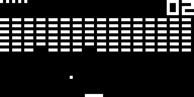
- The graphics system: The chip 8 has one instruction that draws sprite to the screen. Drawing is done in XOR mode and if a pixel is turned off as a result of drawing, the VF register is set. This is used for collision detection.
- 图形系统: chip 8有一个指令用于显示精灵在屏上。画图用的XOR模式,如果一个像素不显示,那个VF寄存器被设置。这用于碰撞检测.
- The graphics of the Chip 8 are black and white and the screen has a total of 2048 pixels (64 x 32). This can easily be implemented using an array that hold the pixel state (1 or 0):
- Chip 8的图形是黑白的,并且屏幕总共只有2048个像素(64*32)。用一个数组就可以很容易的保持它的状态(1或0)
|
unsigned char gfx[64 * 32]; |
- Interupts and hardware registers. The Chip 8 has none, but there are two timer registers that count at 60 Hz. When set above zero they will count down to zero.
- 中断和硬件寄存器,Chip 8没有,但是有两个定时器,以60HZ倒计。当设置大于0时,就倒计到0;
|
unsigned char delay_timer; unsigned char sound_timer; |
- The system’s buzzer sounds whenever the sound timer reaches zero.当声音定时器倒计到0时,系统的蜂鸣器就会发音.
It is important to know that the Chip 8 instruction set has opcodes that allow the program to jump to a certain address or call a subroutine.
Chip 8指令集有允许跳转到某个地址或者调用子程序的功能,这一点非常重要。我们需要知道。
While the specification don’t mention a stack, you will need to implement one as part of the interpreter yourself.
而文档中并没有提到一个栈,你需要自己在解释器中去实现一个。
The stack is used to remember the current location before a jump is performed.
栈用于记住指令跳转前当前的地址。
So anytime you perform a jump or call a subroutine, store the program counter in the stack before proceeding.
所以任何时候,你执行一个跳转或者调用子程序前,存储当前的程序记数器到栈中。
The system has 16 levels of stack and in order to remember which level of the stack is used, you need to implement a stack pointer (sp).
这个系统有16级堆栈,为了记住那个栈被使用,你需要实现一个堆栈指针(sp)
|
unsigned short stack[16]; unsigned short sp; |
Finally, the Chip 8 has a HEX based keypad (0x0-0xF), you can use an array to store the current state of the key.
最后,Chip 8有一个基本的键盘(0x0-0xf)HEX.你可以用一个数组记录当前key的状态
|
unsigned char key[16]; |
Game Loop游戏循环
To give you an idea on how to design your emulator, I made a small example of a layout. It does not teach you how to use GLUT or SDL to handle graphics and input but merely shows you how the flow of your emulator should be.
为了展示如何设计模拟器,我做了一个小例子,这个例子没有展示如何命名用GLUT,或SDL.处理图形和输入,只仅仅为了告诉你模拟器是什么样子。
|
1 2 3 4 5 6 7 8 9 10 11 12 13 14 15 16 17 18 19 20 21 22 23 24 25 26 27 28 29 30 31 32 |
#include #include // OpenGL graphics and input #include "chip8.h" // Your cpu core implementation
chip8 myChip8;
int main(int argc, char **argv) { // Set up render system and register input callbacks setupGraphics(); setupInput();
// Initialize the Chip8 system and load the game into the memory myChip8.initialize(); myChip8.loadGame("pong");
// Emulation loop for(;;) { // Emulate one cycle myChip8.emulateCycle();
// If the draw flag is set, update the screen if(myChip8.drawFlag) drawGraphics();
// Store key press state (Press and Release) myChip8.setKeys(); }
return 0; } |
- Line 3-5: In this example we assume you will create a separate class to handle the opcodes.3-5行:这个例子我们假设你将创建了一个类来处理操作码.
- Line 10-11: Setup the graphics (window size, display mode, etc) and input system (bind callbacks)设置图形(窗口大小,显示模式,等)和输入系统(绑定回调子函数)
- Line 14: Clear the memory, registers and screen清除内存寄存器和屏幕
- Line 15: Copy the program into the memory拷贝程序到内存
- Line 21: Emulate one cycle of the systems模拟系统的一个周期。
- Line 24: Because the system does not draw every cycle, we should set a draw flag when we need to update our screen. Only two opcodes should set this flag:
- 由于系统并不是每个周期都要显示,我们应设置显示标志,当我们需要更新屏幕时。只有两条操作码设置这个标志。
- 0x00E0 – Clears the screen清屏
- 0xDXYN – Draws a sprite on the screen 在屏上显示精灵
- Line 28: If we press or release a key, we should store this state in the part that emulates the keypad
- 如果我们按下或释放一个按键 ,我们应将它的状态存在模拟的键盘的上。
Emulation cycle模拟周期
Next we will look into the emulation cycle.下面,我们要看看模拟周期
|
void chip8::initialize() { // Initialize registers and memory once }
void chip8::emulateCycle() { // Fetch Opcode // Decode Opcode // Execute Opcode
// Update timers } |
Every cycle, the method emulateCycle is called which emulates one cycle of the Chip 8 CPU. During this cycle, the emulator will Fetch, Decode and Execute one opcode.
每个周期,这个方法emulateCycle会被调用,当模拟Chip8 cpu的一个周期时.在这个周期中,模拟器将要读取,译码和执行一个操作指令.
Fetch
opcode 取指令
During this step, the system will fetch one opcode from the memory at the
location specified by the program counter (pc).
在这一步,系统将从内存中,取 pc计数器指定的地址处的一条指令
In our Chip 8 emulator, data is stored in an array in which each address contains one byte.
在我们的Chip 8模拟器中,数据存储在一个数组中,每个地址包含一个字节.
As one opcode is 2 bytes long, we will need to fetch two successive bytes and merge them to get the actual opcode.
由于一个操作码有两个字节,我们将要取两个连续的字节,并把它们合成一个真正的操作码.
To demonstrate how this works we will be using opcode 0xA2F0.为了展示是如何工作的,我们用0XA2F0这个操作码
|
// Assume the following: memory[pc] == 0xA2 memory[pc + 1] == 0xF0 |
In order to merge both bytes and store them in an unsigned short (2 bytes datatype) we will use the bitwise OR operation:为了合并两个字节并存储在一个unsigned short(2个数据字节)中,我们使用位操作,OR操作.
|
opcode = memory[pc] << 8 | memory[pc + 1]; |
So what did actually happen?那么实际发生了什么呢?
First we shifted 0xA2 left 8
bits, which adds 8 zeros.我们将0xA2向左移动了8位,增加了8个0.
|
0xA2 0xA2 << 8 = 0xA200 HEX 10100010 1010001000000000 BIN |
Next we use the bitwise OR operation to merge them:然后,我们OR操作合并它们.
|
1010001000000000 | // 0xA200 11110000 = // 0xF0 (0x00F0) ------------------ 1010001011110000 // 0xA2F0 |
Decode
opcode 译码
As we have stored our current opcode, we need to decode the opcode and check
the opcode table to see what it means. We will continue with the same opcode:
当我们存储了操作码后,我们需要译码,并且从操作码表中查操它是什么意思。我们还是同一个操作码
|
0xA2F0 // Assembly: mvi 2F0h |
If we take a look at the opcode table, it tells us the following:从操作表中可以看出,它告诉我们如下信息:
- ANNN: Sets I to the address NNN 设置I寄存器为NNN
We will need to set index register I to the value of NNN (0x2F0).我们需要将I索引寄存器设计为NNN,(0x2f0).
Execute
opcode执行操作码
Now that we know what to do with the opcode, we can execute the opcode in our
emulator.
现在,我们知道了操作码的作用,我们可以在模拟器上执行操作码了.
For our example instruction 0xA2F0 it means that we need to store the value 0x2F0 into index register I.
在我们的例子中,指令0xa2f0它的意思是:我们需要将值0x2f0存到索引寄存器.
As only 12 bits are containing the value we need to store, we use a bitwise AND operator (&) to get rid of the first four bits (nibble):
由于我们要存储的值只包含12位,我们需要使用位与操作,去掉第一个4位的值(半字节)
|
1010001011110000 & // 0xA2F0 (opcode) 0000111111111111 = // 0x0FFF ------------------ 0000001011110000 // 0x02F0 (0x2F0) |
Resulting code:结果码
|
I = opcode & 0x0FFF; pc += 2; |
Because every instruction is 2 bytes long, we need to increment the program counter by two after every executed opcode.
由于每条指令是2个字节长,我们需要在每指执行后增加程序计数器2.
This is true unless you jump to a certain address in the memory or if you call a subroutine (in which case you need to store the program counter in the stack). If the next opcode should be skipped, increase the program counter by four.
这就是实际情况,除非你跳转到内存中的某个地址,或者你调用了一个子程序(这种情况,你需要存储程序计数器到栈中).如果下个操作码应该跳过,要给程序计数器增加4.
Timers定时器
Besides executing opcodes, the Chip 8 also has two timers you will need to
implement.
除了执行操作码,Chip 8也还有两个定时器需要实现。
As mentioned above, both timers (delay timer and sound timer) count down to zero if they have been set to a value larger than zero.
就像上面提到的,两个定时器(延时定时器和声音定时器),如果将它们的值设为大于0,它们将倒计为0;
Since these timers count down at 60 Hz, you might want to implement something that slows down your emulation cycle (Execute 60 opcodes in one second).
由于这些定时器倒计是以60hz为单位。你可能想实现一些处理以降低你的模拟周期(在一系中执行60个操作码)
Getting started现在开始
Now that you know the basics of emulation and how the system works, it is time to put all pieces together and start coding the emulator.
现在你已知道了模拟的概念和系统是如何运行的。现在要把这些片段组合在一起,开始写模拟器了.
Initialize
system初始化系统.
Before running the first emulation cycle, you will need to prepare your system
state. Start clearing the memory and resetting the registers to zero.
在你运行第一个模拟周期之前,你需要准备系统状态。开始清理内存和寄存器为0;
While the Chip 8 doesn’t really have aBIOS or firmware, it does have a basic fontset stored in the memory. This fontset should be loaded in memory location 0x50 == 80 and onwards.
Chip 8并没有真正的BIOS或者固件 。它有基本的字符集存在内存中,这个字符集需要加载到内存地址0x50== 80,等等。
More details about how the fontset works can be found at the end of this guide.
关于这个字符集是如何工作的在本文的后面.
Another important thing to remember is that the system expects the application
to be loaded at memory location 0x200.
This means that your program counter should also be set to this location.
另外一个很重要的,需要记住 的是系统期望应用存在地址0x200处,这就是说,你的程序计数器指针也要设到这个位置.
|
void chip8::initialize() { pc = 0x200; // Program counter starts at 0x200 opcode = 0; // Reset current opcode I = 0; // Reset index register sp = 0; // Reset stack pointer
// Clear display // Clear stack // Clear registers V0-VF // Clear memory
// Load fontset for(int i = 0; i < 80; ++i) memory[i] = chip8_fontset[i];
// Reset timers } |
Loading
the program into the memory加载代码到内存
After you have initialized the emulator, load the program into the memory (use
fopen in binary mode) and start filling the memory at location: 0x200 == 512.
初始化模拟器后,加载代码到内存中(以二进制方式用fopen打开)并且在在址0x200==512处,开始填充内存
|
for(int i = 0; i < bufferSize; ++i) memory[i + 512] = buffer[i]; |
Start
the emulation开始模拟
Our system is now ready to execute its first opcode. As mentioned above, we
should fetch, decode and execute the opcode.
现我,我们的系统准备执行第一个操作码了,就如前面所说,我们需要取指令,译码,并执行指令。
In this example we start by reading the first 4 bits of the current opcode to find out what the opcode is and what the emulator needs to do:
在这个例子中,我们读取当前操作码的前4位,并找出这个操作码是什么,以及模拟器需要做什么.
|
void chip8::emulateCycle() { // Fetch opcode opcode = memory[pc] << 8 | memory[pc + 1];
// Decode opcode switch(opcode & 0xF000) { // Some opcodes //
case 0xA000: // ANNN: Sets I to the address NNN // Execute opcode I = opcode & 0x0FFF; pc += 2; break;
// More opcodes //
default: printf ("Unknown opcode: 0x%X\n", opcode); }
// Update timers if(delay_timer > 0) --delay_timer;
if(sound_timer > 0) { if(sound_timer == 1) printf("BEEP!\n"); --sound_timer; } } |
In some cases we can not rely solely on the first four bits to see what the opcode means. For example, 0x00E0 and 0x00EE both start with 0x0. In this case we add an additional switch and compare the last four bits:
在某些情况下,我们不能仅依赖孤立出来的前4位,表示操作码的意思。比如,0x00e0和0x00ee,都是以0x0开头。这种情况下我们需要增加另一个switch 并比较后低4位。
|
// Decode opcode switch(opcode & 0xF000) { case 0x0000: switch(opcode & 0x000F) { case 0x0000: // 0x00E0: Clears the screen // Execute opcode break;
case 0x000E: // 0x00EE: Returns from subroutine // Execute opcode break;
default: printf ("Unknown opcode [0x0000]: 0x%X\n", opcode); } break;
// more opcodes // } |
Opcode examples 操作码例子
Lets take a look at some more opcodes that might look daunting at first.让我们看看一些更多的操作码,乍一看有点让人感到畏惧。
Example
1: Opcode 0x2NNN例1:操作码 0x2nnn
This opcode calls the subroutine at address NNN. Because we will need to
temporary jump to address NNN, it means that we should store the current
address of the program counter in the stack.
这个操作码调用地址NNN处的子程序.由于我们需要临时跳转到地址NNN处。那么我们先得将程序计数器存入栈中。
After storing the value of the program counter in the stack, increase the stack pointer to prevent overwriting the current stack.
当把程序计数器的值存入到栈中后,增加栈指示器,以名复写了当前的栈。
Now that we have stored the program counter, we can set it to the address NNN. Remember, because we’re calling a subroutine at a specific address, you should not increase the program counter by two.
现在由于我们已经存好了程序计数器,我们可以把地址NNN设到程序计数器上了。记住 ,因为我们调用了某个指定地址的子程序。程序计数器要增加2;
|
case 0x2000: stack[sp] = pc; ++sp; pc = opcode & 0x0FFF; break; |
Example
2: Opcode 0x8XY4 例2:操作码 0x8xy4
This opcode adds the value of VY to VX. Register VF is set to 1 when there is a
carry and set to 0 when there isn’t.
这条指令是将VY的值 加到VX上,当有进位时寄存器VF设为1,无进位设为0.
Because the register can only store values from 0 to 255 (8 bit value), it means that if the sum of VX and VY is larger than 255, it can’t be stored in the register (or actually it starts counting from 0 again).
由于寄存器的值只能存储0到255的值(8bit),这就是说VX和VY中的值大于255.它不能存于计存器中(或者实际上它又从0开始)
If the sum of VX and VY is larger than 255, we use the carry flag to let the system know that the total sum of both values was indeed larger than 255. Don’t forget to increment the program counter by two after executing the opcode.
如果VX和VY的值大于255,我们使用进位标记通知系统,两个值 的合实际上大于255.不要忘了执行操作码后程序计数器加2;
|
case 0x0004: if(V[(opcode & 0x00F0) >> 4] > (0xFF - V[(opcode & 0x0F00) >> 8])) V[0xF] = 1; //carry else V[0xF] = 0; V[(opcode & 0x0F00) >> 8] += V[(opcode & 0x00F0) >> 4]; pc += 2; break; |
Example
3: Opcode 0xFX33例子3:操作码0xfx33
Stores the Binary-coded decimal representation of VX at the addresses I, I plus
1, and I plus 2
将VX中以十进制表示的值存会话到地址I,I加 1,l加2处。
I have to confess that I couldn’t to figure out how to implement this opcode, so I used TJA’s solution.
我得承认我不知道如何实现这个操作,所以我用了TJA’s solution.的方法。
|
case 0x0033: memory[I] = V[(opcode & 0x0F00) >> 8] / 100; memory[I + 1] = (V[(opcode & 0x0F00) >> 8] / 10) % 10; memory[I + 2] = (V[(opcode & 0x0F00) >> 8] % 100) % 10; pc += 2; break; |
Handling graphics and input处理图形和输入
Drawing
pixels画像素
The opcode responsible for drawing to our display is 0xDXYN. The Wikipedia description tells us the following:
负责显示的操作码是0xDXYN。维基是这样描述的
- Draws a sprite at coordinate (VX, VY) that has a width of 8 pixels and a height of N pixels.在(VX,VY)坐标处画一个精灵,这个精灵宽8个像素,高N个像素。
- Each row of 8 pixels is read as bit-coded starting from memory location I; I value doesn’t change after the execution of this instruction.从内存地址I处读取,每行8个像素,以位编码的,执行这条指令后I的值不改变。
- As described above, VF is set to 1 if any screen pixels are flipped from set to unset when the sprite is drawn, and to 0 if that doesn’t happen.如前所述,当画精灵时,如果屏上任何像素发生了从置位到取消置位的变化,VF置为1,并且,如果没有变化VF置0
As the description of the opcode is telling us, the Chip 8 actually draws on the screen by drawing sprites. It will give us the location of where the sprite needs to be drawn (the opcode tells us which V register we need to check to fetch the X and Y coordinates)
就如操作码所描述的,Chip 8实际上在屏上以画精灵的方式显示的。它将会告诉我们精灵所显示的位置(操作码告诉我们到那个V寄存器,取x,y坐标)
and the number of rows (N). The width of each sprite is fixed (8 bits / 1 byte). The state of each pixel is set by using a bitwise XOR operation. This means that it will compare the current pixel state with the current value in the memory. If the current value is
以及行(N).精灵的宽度是固定的(8位或1个字节)。每个像素的状态由 XOR异或操作设置。也就是说我们要比较当前的像素的状态和内存的值 。如果当前的值不同于内存中的值 ,位将置1,如果两个值相同,位将置0.
different from the value in the memory, the bit value will be 1. If both values match, the bit value will be 0.
|
01000101 ^ 11110011 = ---------- 10110110 |
Lets assume it the opcode was 0xD003. This means it wants to draw a sprite at location 0,0 which is 3 rows high. At memory location I, the following values were set:
让我们假设操作码是0xd003.这表示我们想在0x,0个画一个3行高的精灵,在内存地址I ,它们的值设置如下
|
memory[I] = 0x3C; memory[I + 1] = 0xC3; memory[I + 2] = 0xFF; |
How do these 3 bytes represent a sprite? Take a look at the binary values of each byte:那个这三个字节表示什么意思呢?看看每个字节的二进制值
|
HEX BIN Sprite 0x3C 00111100 **** 0xC3 11000011 ** ** 0xFF 11111111 ******** |
You should use the binary representation to fill your array (gfx[]). However, before setting the value in gfx[] using the XOR operator, you will also need to check if any of the pixels changed from 1 to 0.
你应该 用二进制的形式填充你的数组(gfx[]).但是,在对(gfx[])使用异或操作之前,还要检查是否有像素发生了从1到0的改变。
If this is the case, you should set the VF register to 1 (This is basically a test for collision detection).如果发生了这种情况,你要将VF设置1(这主要是用于碰撞检测)
Example of the implementation of opcode 0xDXYN 0xDXYN 的实现例子。
|
1 2 3 4 5 6 7 8 9 10 11 12 13 14 15 16 17 18 19 20 21 22 23 24 25 26 |
case 0xD000: { unsigned short x = V[(opcode & 0x0F00) >> 8]; unsigned short y = V[(opcode & 0x00F0) >> 4]; unsigned short height = opcode & 0x000F; unsigned short pixel;
V[0xF] = 0; for (int yline = 0; yline < height; yline++) { pixel = memory[I + yline]; for(int xline = 0; xline < 8; xline++) { if((pixel & (0x80 >> xline)) != 0) { if(gfx[(x + xline + ((y + yline) * 64))] == 1) V[0xF] = 1; gfx[x + xline + ((y + yline) * 64)] ^= 1; } } }
drawFlag = true; pc += 2; } break; |
- Line 3-4: Fetch the position and height of the sprite取精灵的位置和高度
- Line 5: Pixel value像素值
- Line 8: Reset register VF复位RF
- Line 9: Loop over each row循环每一行
- Line 11: Fetch the pixel value from the memory starting at location I从地址I处开始,读取内存的像素值。
- Line 12: Loop over 8 bits of one row循环一行8位
- Line 14: Check if the current evaluated pixel is set to 1 (note that 0x80 >> xlinescan through the byte, one bit at the time)检测当前的像素是否置1(注意 0x80 >> xline 扫描一个字节,一位一次)
- Line 16-17: Check if the pixel on the display is set to 1. If it is set, we need to register the collision by setting the VF register检测显示的像素是否置为1,如果是,我们需要通过设置VF寄存器来注册碰撞。
- Line 18: Set the pixel value by using XOR使用XOR设置像素值.
- Line 23: We changed our gfx[] array and thus need to update the screen.我们改变了 gfx[] 数组,因为要列梳妆打屏幕.
- Line 24: Update the program counter to move to the next opcode更新程序计数器,以取下一个操作码.
Input输入
The Chip 8 system uses a simple HEX keypad that allows users to interact with
the system.
Chip 8系统,使用了一个HEX键盘,我们通过它和系统交互。
For our emulator this means we need to implement a method that will set the state of each key in the variable that handles the key states.
对我们的模拟器来说,我们需要实现一个方法来设置每个键的状态,并处理键的各种状态。
Every cycle you should check the key input state and store it in key[].每个周期我们都要检测键的输入,并将其存在key[].
It actually doesn’t matter what value you store, because opcode 0xEX9E and 0xEXA1 only check if a certain key is pressed or isn’t pressed.
实际上,无论存什么值 ,都没关系,因为操作码0xex9e和oxexa1只检测是某个键是否按下。
Opcode 0xFX0A only waits for a key press, and when it receives one, it stores the key name in the register and not the key state.
操作码0xFX0A仅等待键按下,并且,当收到按下时,它将key的名字存到寄存吕,并取反key状态
|
case 0xE000: switch(opcode & 0x00FF) { // EX9E: Skips the next instruction // if the key stored in VX is pressed注意0f00,其中的f就是按下键位码 case 0x009E: if(key[V[(opcode & 0x0F00) >> 8]] != 0) pc += 4; else pc += 2; break; |
Below you’ll find an example of the original keypad layout. It does not really matter how you implement the key mapping, but I suggest something as on the right side.
下面你看到的是原始keypad的布局,你如何实现它并没有关系。但是我建议你用右边的 。
|
Keypad Keyboard +-+-+-+-+ +-+-+-+-+ |1|2|3|C| |1|2|3|4| +-+-+-+-+ +-+-+-+-+ |4|5|6|D| |Q|W|E|R| +-+-+-+-+ => +-+-+-+-+ |7|8|9|E| |A|S|D|F| +-+-+-+-+ +-+-+-+-+ |A|0|B|F| |Z|X|C|V| +-+-+-+-+ +-+-+-+-+ |
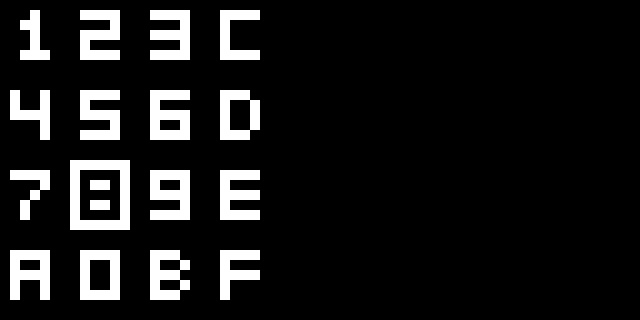
CHIP-8 fontset 字符集
This is the Chip 8 font set. Each number or character is 4 pixels wide and 5 pixel high.下面是Chip 8的字符值,4像素宽,5像素高。
|
unsigned char chip8_fontset[80] = { 0xF0, 0x90, 0x90, 0x90, 0xF0, // 0 0x20, 0x60, 0x20, 0x20, 0x70, // 1 0xF0, 0x10, 0xF0, 0x80, 0xF0, // 2 0xF0, 0x10, 0xF0, 0x10, 0xF0, // 3 0x90, 0x90, 0xF0, 0x10, 0x10, // 4 0xF0, 0x80, 0xF0, 0x10, 0xF0, // 5 0xF0, 0x80, 0xF0, 0x90, 0xF0, // 6 0xF0, 0x10, 0x20, 0x40, 0x40, // 7 0xF0, 0x90, 0xF0, 0x90, 0xF0, // 8 0xF0, 0x90, 0xF0, 0x10, 0xF0, // 9 0xF0, 0x90, 0xF0, 0x90, 0x90, // A 0xE0, 0x90, 0xE0, 0x90, 0xE0, // B 0xF0, 0x80, 0x80, 0x80, 0xF0, // C 0xE0, 0x90, 0x90, 0x90, 0xE0, // D 0xF0, 0x80, 0xF0, 0x80, 0xF0, // E 0xF0, 0x80, 0xF0, 0x80, 0x80 // F }; |
It might look just like an array of random numbers, but take a close look at the following:它可能看起来像随机数字,但仔细看看下面的图。
|
DEC HEX BIN RESULT DEC HEX BIN RESULT 240 0xF0 1111 0000 **** 240 0xF0 1111 0000 **** 144 0x90 1001 0000 * * 16 0x10 0001 0000 * 144 0x90 1001 0000 * * 32 0x20 0010 0000 * 144 0x90 1001 0000 * * 64 0x40 0100 0000 * 240 0xF0 1111 0000 **** 64 0x40 0100 0000 * |
Look at the left example were we are drawing the number 0. As you can see it see it consists out of 5 values. Of every value, we use the binary representation to draw. Note that only the first four bits (nibble) are used for drawing a number or character.
看看左边画0的例子,就如你所见它由5个值组成。每个值 中,我们用二进制表示的形式来画的。注意只有前4位用于显示数字和字符。
Conclusion结尾
Hopefully this guide provided you enough information to get you started with your own emulator project.
希望本文给你,编写自己的仿真器,提供了足够的信息。
At least you should now have a basic understanding of how emulation works and perhaps a better understanding of how a CPU executes opcodes.
至少你现在应该对模拟器的运作有了基本的理解了,也许对CPU如可执行操作码有了更深入的认识.
I have included my own implementation of a Chip 8 interpreter below which you can use as a reference.
我已经包含了一个Chip8 的一个实现,可以用于参考.
The zip file contains a binary for Windows but also includes the full source code of the emulator. zip文件包括了一个windows的二进制实现,以及源码.
Because the full source code is supplied, I recommend only looking atchip8.cpp file as a last resort to see how I implemented a particular opcode. 由于包括了所有代码,建议只看chip8.xpp,看看我是如何实现特别码操作的.
The filechip8.h and main.cpp should be safe to view without spoiling too much. Actually, main.cppmostly contains GLUT code which you can reuse in other (non-emulator related) projects as well.
文件chip8.h和main.cpp应。实际上main.cpp主要包含了GLUT代码,可以在其他平台重用(非模拟器相关的).
- myChip8 (3642) - 87.36 kB – Latest (Windows binary + Source code)
- Early version of myChip8 from 2003 (contains a nice debugger)
- An Android port I did in 2008
Let me know if you find this guide useful! If you have questions or think that essential parts are missing, please use the comment section !如果你发现这个向导很有用,请你告诉我,如果你用问题或认真重要的部分丢失了。请用评论部分。

Credits成员
Special thanks to the following persons (many only known by their pseudonym)
who have helped me greatly with my own emulation projects in the past and
present.
特别感谢这些人(许多人只知道他们的笔名),无论过去还是现在,在实现我的模拟器的过程中他们给予了很大的帮助.
- ector & F|RES (Dolphin-emu team)
- Saqib, zenogais, Absolute0, Shadow, gigaherz, Florin, Goldfinger (PCSX2 team)
- drk||Raziel & ZeZu (nullDC team)
- Hacktarux (Mupen64)
- Muad (nSX2)
- pSXAuthor (pSX)
- Shadowprince, Linker, Aprentice, SculleatR, ShizZy, Dave2001
Suggestions建议
After you have completed your first Chip 8 emulator, you might want to try one of the following things:在你完成你的Chip 8模拟器后,你应该试着完成下面的事情:
- Add Super CHIP-8 Opcodes 增加 超级CHIP-8的操作码
- Use function pointers instead of a giant switch statement 使用函数指针,替换大量的switch 语句
- Improve graphics by adding filters (Hqx)通过增加过滤器增强图形
- Port it to other platforms (Mobile?) or languages移植到其他的平台或语言
- Move on to a more complex project for example emulating a Gameboy (Z80 processor)继续研究更加复杂的模拟器,比如 Gameboy (Z80 processor)
Resources 资源
- http://en.wikipedia.org/wiki/CHIP-8 – System information
- Cowgod’s Chip-8 Technical Reference v1.0 – Recommended
- Chip8 tutorial – Goldroad.co.uk (mirror)
- (S)Chip 8 instruction set – Goldroad.co.uk (mirror)
- David Winter’s CHIP-8 emulation page – Contains some games
- (S)CHIP-8 instruction set overview – (Erik Bryntse)
- Chip8 emulator topic on Emutalk
- Chip8 emulator topic on NGemu
Advanced emulator resources高级模拟器资源
- Zilmar’s Emubook
- Zenogais Emulation Tutorials – (Offline, but available through Archive.org)
- Zenogais’ Emulation Tutorials – (mirror)
- Dynamic Recompiler – (mirror)
- Array of Function Pointers – (mirror)
- Introduction to Emulation Part 1 – (mirror)
- Introduction to Emulation Part 2 – (mirror)
- Laying the Ground For An Emulator – (mirror)
Bookmark & Share书签和共享
posted on 2014-10-15 19:48 EarlyBird 阅读(3175) 评论(1) 编辑 收藏 举报

